Table of Contents
Advertisement
Quick Links
SELF-DEPENDENT REGULATION
BLOCK USER'S MANUAL
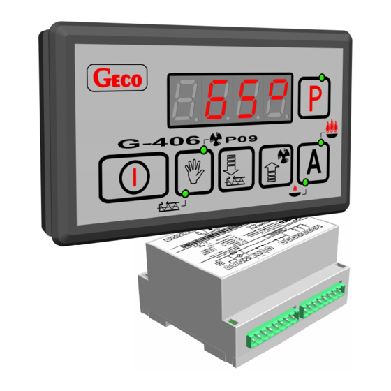
G-406-P09
FOR CONTROL CENTRAL
HEATING SYSTEM BOILERS
WITH FEEDING SCREW AND FAN
ROTATION SMOOTH CONTROL
Program Version 00
You are politely requested for the familiarization with the manual prior to making the
connection and activating any of our machines. Should you have any doubts, please do not
hesitate to contact our firm between 8 a.m. and 16 p.m..
Note:
The most recent update release date is provided at the bottom of each following page. Please,
always use the most recent version of the manual, which can be obtained by mail free of charge
after the previous order.
Advertisement
Table of Contents

Related Manuals for Geco G-406-P09


Summary of Contents for Geco G-406-P09
- Page 1 SELF-DEPENDENT REGULATION BLOCK USER’S MANUAL G-406-P09 FOR CONTROL CENTRAL HEATING SYSTEM BOILERS WITH FEEDING SCREW AND FAN ROTATION SMOOTH CONTROL Program Version 00 You are politely requested for the familiarization with the manual prior to making the connection and activating any of our machines. Should you have any doubts, please do not hesitate to contact our firm between 8 a.m.
-
Page 2: Table Of Contents
MIXING PUMP HANDLING ....................11 UTILITY HOT WATER VESSEL HANDLING ............... 11 8.1. A .................... 11 SSEMBLY AND CONNECTION 8.2. C ................12 ONFIGURATION OF THE PARAMETERS METHOD OF CONNECTING THE EQUIPMENT TO THE G-406-P09 CONTROLLER ..........................13 TROUBLESHOOTING GUIDE ..................14... -
Page 3: General Characteristics
230 V, such as fan, fuel feeding unit, central heating system and utility hot water circulating pumps. If the unit is to act as the central heating system boiler controller, the G-406-P09 stabilizes the temperature of water and controls the process of fuel combustion in the boiler, preventing damping a fire. -
Page 4: Wiring System And Rules Of Connection
4.2. Controller interlock through the room thermostat If the external room thermostat is connected to the G-406-P09 unit (see figure 2), which will be activated, i.e. will cause the output terminals to join, when the temperature preset for the heated rooms is exceeded, the unit in question will enter the interlock status. -
Page 5: Exceeding The Allowable Temperature Of The Fuel In The Feeding Screw
The controller will wait for the period of one minute so that the electric grid can stabilize, after which the operation with the previously programmed values of parameters will be resumed. PPUH „GECO” Sp. z o.o. Edition II RELEASE DATE 2010-12-02... -
Page 6: G-406-P09 Handling
When the pushbutton is pressed again, the feeding screw is deactivated and the control diode goes off. PPUH „GECO” Sp. z o.o. Edition II RELEASE DATE 2010-12-02... -
Page 7: Automatic Operation
7. The display will show the temperature of water measured. When the pushbutton is pressed, all the equipment is deactivated and the manual operation mode resumed. PPUH „GECO” Sp. z o.o. Edition II RELEASE DATE 2010-12-02... -
Page 8: Sustaining Mode Operation
If the controller detected the alarm in the course of manual operation mode, the central heating system circulation pump will be activated. This alarm will automatically go off when the temperature in the boiler drops below 85 degrees Centigrade. PPUH „GECO” Sp. z o.o. Edition II RELEASE DATE 2010-12-02... -
Page 9: User Parameters Configuration
The controller with display the u0 parameter value. 2. Press the pushbutton again. The controller will store of the value of the u0 parameter and will switch to u1. PPUH „GECO” Sp. z o.o. Edition II RELEASE DATE 2010-12-02... -
Page 10: Time Of Stopping The Feeding Screw (U2)
The subsequent pressing of the pushbutton will cause the return to the mode from which the programming mode was called for, as well as the deactivation of the programming control diode. PPUH „GECO” Sp. z o.o. Edition II RELEASE DATE 2010-12-02... -
Page 11: Mixing Pump Handling
UTILITY HOT WATER VESSEL HANDLING The G-406-P09 controller allows the connection of the additional pump controlling heating the hot water in the vessel. -
Page 12: Configuration Of The Parameters
Figure 1. Central heating system block diagram (one circulating pump and one utility hot water vessel replenishing pump). Comments: Utility hot water temperature sensor is the additional sensor (option), not supplied together with the G-406-P09. The sensor in question may also be purchased against the additional payment from the manufacturer, i.e. GECO. (**) Sensors cables may be shortened or extended in any arbitrary way, subject to the following rules: the sensor cable should not be trimmed at the distance <... -
Page 13: Method Of Connecting The Equipment To The G-406-P09 Controller
CONTROLLER Figure 2. Diagram of equipment connection to the G-406-P09 controller Important: The additional equipment to the G-406-P09 controller may be connected only by the person holding the certificate for performing electrical assembly works. PPUH „GECO” Sp. z o.o. Edition II... -
Page 14: Troubleshooting Guide
• condition of the feeding connectors • the condition of feeding connectors screwing in • the correctness of the connection of the actuating module with the control panel • connect another data transfer tape. PPUH „GECO” Sp. z o.o. Edition II RELEASE DATE 2010-12-02... - Page 15 USER’S MANUAL G-406-P09 STRONA 15 PPUH „GECO” Sp. z o.o. Edition II RELEASE DATE 2010-12-02...
- Page 16 P.P.U.H. „Geco” Sp. z o. o. ul. Zarzecze 112 A 30-134 Kraków POLAND tel. 012 6369811, 6361290 fax. 012 6362002 Email: geco@geco.pl www.geco.pl...
Need help?
Do you have a question about the G-406-P09 and is the answer not in the manual?
Questions and answers