Enerpac PUJ-1400B Service Instructions
Hide thumbs
Also See for PUJ-1400B:
- Instruction sheet (56 pages) ,
- Instruction sheet (44 pages) ,
- Instruction sheet (96 pages)
Advertisement
Quick Links
L1738
Rev. B
01/07
SERVICE INSTRUCTIONS: These Service Instructions are intended to be used by qualified personnel at Authorized
Enerpac Service Centers. Users of Enerpac equipment should see the pump Instruction Sheet for installation, operation,
and maintenance information.
IMPORTANT: This guide shows how to completely tear down the pump, which may not be required. The pump should be tested prior
to service to avoid unnecessary labor. Please refer to Pump Test Procedure on page 2 and Troubleshooting Guide on page 4.
YOU MAY NEED:
✔ test bench
✔ 0-10,000 psi
hand pump
✔ 0-1 5,000 psi
pressure gauge
DISASSEMBLY
WARNING: Be sure pump is disconnected from
power source before disassembling.
Shroud Removal
1.
Remove the six 1/8" socket head screws (item 52) from
bottom of yellow pump motor shroud.
2.
Remove shroud (item 51) from pump, making sure foam
baffle (item 53) stays on electric motor. Use care to not
disconnect or damage wiring in the shroud. NOTE: Foam
baffle may be glued to shroud.
Wire Removal
NOTE: Refer to wiring diagram on Repair Parts sheet. Mark wires
before removing to aid during re-assembly.
1.
Disconnect black power cord wire from thermostat (item 37).
2.
Disconnect black power switch jump wire from thermostat
(item 37).
3.
PUJ only: Disconnect black pendant wire from transformer
(item 22) at connection #8.
4.
PUJ only: Disconnect white pendant wire from relay (item
23).
5.
PUJ only: Disconnect transformer lead wire (item 67) from
white power cord wire and black motor wire by unplugging
connector.
6.
PUJ only: Disconnect black motor wire from relay (item 23)
and power switch (item 54) by unplugging respective flags.
7.
PUM only: Disconnect black motor wire from power switch
(item 54).
Shroud may now be removed from pump.
8.
Disconnect power cord (item 40) and pendant cord (item 62)
from the pump by removing their anchor screws.
9.
Remove foam baffle (item 53) from motor (item 2).
NOTE: Foam baffle may be glued to motor.
®
✔ ammeter
✔ V-152 relief valve
✔ unrestricted hose
✔ graduated cylinder
✔ toque wrench
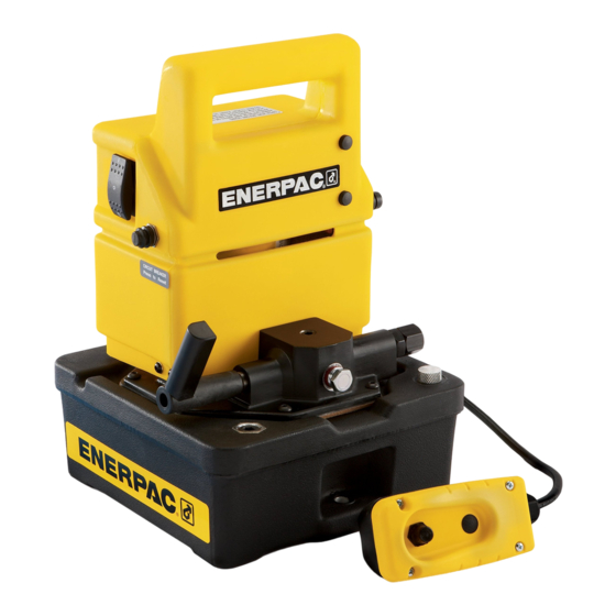
Service Instructions
PUJ/PUM-1400B AND PUJ/PUM-1400E
✔ box end wrenches
✔ Allen wrenches
(5/32" 7/32")
✔ roll pin punch (5/32")
✔ snap-ring pliers
ASSEMBLY
Refer to Repair Parts Sheet L1481 and use repair kit PUJ-
1400BK.
IMPORTANT: Use suitable solvent to clean all parts prior to
assembly. Clean RTV sealant from motor end cap, top and
bottom of pump manifold and reservoir assembly. Rebuild using
replacement items from repair kit.
Assemble Pump Shaft
1.
Assemble gear (item 11) and disc bearings into pump
manifold. Install one white bearing (item 28 from new kit)
above the gear, the black bearing (item 13) directly below
gear and the other new white bearing at the bottom.
2.
Install shaft (item 16) through lower manifold bearing, gear
and washers, and into upper manifold bearing.
3.
Install new roll pin (item 12) from kit through hole in gear and
shaft (items 11 and 16). With these holes aligned, use a
5/32" roll pin punch and tap the roll pin onto place.
4.
Assemble bearings (items 14 and 15) to shaft. Using
retaining ring pliers, place retaining ring (item 21) onto shaft.
Install Motor
For "E" version, refer to repair parts sheet notes.
NOTE: Before installation, apply a thin continuous bead of RTV
sealant to motor end cap at three locations: around the tie rods
and at the center boss.
1.
Position the motor (item 2) onto manifold with wire leads at
top of motor facing to the left with hydraulic output port facing
you.
2.
Secure the motor to the manifold by placing the two lock
washers (item 3) and nuts (item 4) on the motor tie rods
under the manifold. Torque nuts to 34-38 in-lbs.
Assemble Piston Block
IMPORTANT: During installation of piston blocks, hold manifold
firmly when tightening cap screws. This will help prevent plunger
spring from cocking block and causing damage to the outlets.
1.
Assemble high-pressure piston block (item 7, small .24
diameter piston).
Refer to Repair Parts Sheet L1481.
✔ O-ring pick
✔ 1/4" coining tool
✔ RTV sealant
✔ solvent
✔ Enerpac hydraulic oil
Advertisement

Related Manuals for Enerpac PUJ-1400B


Summary of Contents for Enerpac PUJ-1400B
- Page 1 01/07 SERVICE INSTRUCTIONS: These Service Instructions are intended to be used by qualified personnel at Authorized Enerpac Service Centers. Users of Enerpac equipment should see the pump Instruction Sheet for installation, operation, and maintenance information. IMPORTANT: This guide shows how to completely tear down the pump, which may not be required. The pump should be tested prior to service to avoid unnecessary labor.
- Page 2 a. Place new white o-ring from kit between block and PUJ only: Connect black motor wire (item 65) flag to relay manifold. (item 23) and then to power switch (item 54). b. Anchor piston block by compressing piston spring against PUJ only: Connect transformer lead wire (item 67) to white eccentric bearing and hold firmly in place.
- Page 3 During this step, observe for any leakage on the underside a. Maximum draw is 9.50 Amps for the 115 VAC model and of the pump. If any leaks are found, stop the test and repair 4.50 Amps for the 220 VAC model. the leaking items.
- Page 4 Tel: +82 32 675 08 36 Fax: +82 32 675 30 02/73 All Enerpac products are guaranteed against defects in workmanship and materials for as long as you own them. 10/30/02 For your nearest authorized Enerpac Service Center, visit us at www.enerpac.com...
Need help?
Do you have a question about the PUJ-1400B and is the answer not in the manual?
Questions and answers