Table of Contents
Advertisement
Quick Links
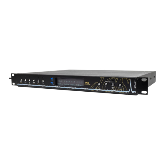
dCS 905
Stereo Analogue to Digital Converter
User Manual
Software Release 1.0x
November 2006
© dCS Ltd. 2004 - 2006
Price UK £17.50 / Euro 25.00
All rights reserved. No part of this publication may be reproduced, stored in or
introduced into a retrieval system, or transmitted in any form, or by any means
(electronic, mechanical, photocopying, recording or otherwise) without the prior
1
written permission of dCS
. Any person who does any unauthorised act in
relation to this publication may be liable to criminal prosecution and civil claims
for damages.
Information contained in this manual is subject to change without notice, and
whilst it is checked for accuracy, no liabilities can be accepted for errors.
1
dCS is Data Conversion Systems Ltd. Company registered in England No. 2072115.
Advertisement
Chapters
Table of Contents

Related Manuals for DCS 905


Summary of Contents for DCS 905
- Page 1 Information contained in this manual is subject to change without notice, and whilst it is checked for accuracy, no liabilities can be accepted for errors. dCS is Data Conversion Systems Ltd. Company registered in England No. 2072115.
- Page 2 905 User Manual Manual for Software Issue 1.0x dCS Ltd November 2006 Page 2 Manual filename: dCS905 Manual v1.0x Eng.doc email: more@dcsltd.co.uk English version web-site: www.dcsltd.co.uk...
-
Page 3: Product Features
905 User Manual Manual for Software Issue 1.0x dCS Ltd November 2006 RODUCT EATURES Formats • DSD, and PCM from 384kS/s down to 32kS/s • Data formats supported are: AES/EBU (XLR and BNC), Dual AES (XLR), Quad AES (XLR), SDIF-2 (PCM and DSD), SDIF-3 (DSD), DSD packed into... -
Page 4: Table Of Contents
Step 2 – Setting the Connectors Step 3 – Connecting the Analogue Inputs Typical Applications..................10 Using a dCS 905 to output DSD 6 Channel PCM Set Up 8 Channel P3D DSD Set Up with Monitoring The Software – The Menu ................14... - Page 5 905 User Manual Manual for Software Issue 1.0x dCS Ltd November 2006 6.4 Unit Identification 6.5 Distributor Details 6.6 RS232 Address 7. Store Menu 7.1 Recall Settings 7.2 Save Settings Fixed Stores The Hardware – Controls and Connectors ...........29...
- Page 6 The unit fails to slave to a Master Clock The unit slaves to Word Clock but not AES/EBU The OVER indicators will not turn off External meter does not show overload, dCS 905 does. The output is full scale noise The display is very dim If You Need More Help ..................83...
-
Page 7: About This Manual
Keywords and Phrases About this Manual If you have not used a dCS 905 before, please read the section “Using your dCS 905 for the first time” on page 72. This manual has been arranged with the most commonly used sections placed first: •... -
Page 8: Step-By-Step Guide
UIDE This section guides you through setting up the unit for basic operation. You may find this useful if you have not used the dCS 905 for a while. Preliminaries The Menu Guide sheet details the menu structure. For more information, see the Menu section, starting on page 14. -
Page 9: Step 1 - Setting The Output Format
Step 2 – Setting the Connectors do this: On the front panel, press the Menu button and select Connectors. do this: If you want to use the 905’s internal clock, use the Ext Sync button to set Internal or select 2.1 Sync Source >... -
Page 10: Using A Dcs 905 To Output Dsd
905 User Manual Manual for Software Issue 1.0x dCS Ltd November 2006 YPICAL PPLICATIONS Using a dCS 905 to output DSD SDIF WCLK dCS 905 CH1(L) CH2(R) Reference In Reference Out AES1 AES2 AES3 AES4 CH1(L) Disconnect mains before removing cover... -
Page 11: Channel Pcm Set Up
905 User Manual Manual for Software Issue 1.0x dCS Ltd November 2006 6 Channel PCM Set Up dCS 905 Master CH1(L) CH2(R) Reference In Reference Out AES1 AES2 AES3 AES4 CH1(L) Disconnect mains before removing cover PUSH PUSH PUSH... -
Page 12: Channel P3D Dsd Set Up With Monitoring
Figure 3 – 8 channel P3D DSD set up with a Master Clock Four dCS 905s and a dCS 995 can be set up as shown above to give 8 channel DSD with additional 16 bit / 44.1kS/s PCM outputs for level monitoring on PCM equipment. - Page 13 905 User Manual Manual for Software Issue 1.0x dCS Ltd November 2006 Page 13 Manual filename: dCS905 Manual v1.0x Eng.doc email: more@dcsltd.co.uk English version web-site: www.dcsltd.co.uk...
-
Page 14: The Software - The Menu
905 User Manual Manual for Software Issue 1.0x dCS Ltd November 2006 – T OFTWARE Press the "Menu" button to open the menu, use the arrow buttons to move around the menu tree. MENU Press the "OK" button to select a menu or setting. Use the "Cancel" button to return to the previous menu level. -
Page 15: Using The Menu
905 User Manual Manual for Software Issue 1.0x dCS Ltd November 2006 Using the Menu The menu gives the user access to a wide range of additional features. It also allows new features and performance enhancements to be added at a later date by software upgrades. -
Page 16: Menu Sequence
905 User Manual Manual for Software Issue 1.0x dCS Ltd November 2006 Menu Sequence Use the flow chart (Figure 4) or the Menu Guide sheet to guide you through the menu more quickly. When you are more familiar with the menu, you will find it more convenient to perform all the operations in one go before finally closing the menu. -
Page 17: Adc Settings Menu
905 User Manual Manual for Software Issue 1.0x dCS Ltd November 2006 Menu 1. ADC Settings 1. ADC Settings 1. ADC Settings 1. ADC Settings 1. ADC 1.4 Noise 1.5 Output Word 1.1 Output Mode 1.2 Filter Settings 1.3 DDC Mode... -
Page 18: Ddc Mode
905 User Manual Manual for Software Issue 1.0x dCS Ltd November 2006 Filter 2 Slightly lower bandwidth, less noise. Filter 3 Filter Lower bandwidth and less noise than Filter 4 Minimum noise with 20kHz bandwidth, intended for metering applications. -
Page 19: Connector Settings Menu
905 User Manual Manual for Software Issue 1.0x dCS Ltd November 2006 2. Connector Settings 2. Connector Settings Menu Menu 2. Connector Settings 2. Connector Settings Menu Menu 2. Connector 2.2 Set 2.1 Sync Source 2.3 DSD Format Settings... -
Page 20: Metering Menu
905 User Manual Manual for Software Issue 1.0x dCS Ltd November 2006 3. Metering 3. Metering Menu Menu 3. Metering 3. Metering Menu Menu 3. Metering 3.2 Metering 3.3 Metering 3.4 Metering 3.1 Peak Hold Menu Type Speed Boost... -
Page 21: Metering Speed
905 User Manual Manual for Software Issue 1.0x dCS Ltd November 2006 History Shows a running history across the display of the highest signal level on either channel. The graduation dots at the right side are full scale (top), -6dB0, -12dB0 and -18dB0. -
Page 22: Display Menu
905 User Manual Manual for Software Issue 1.0x dCS Ltd November 2006 4. Display 4. Display Menu Menu 4. Display 4. Display Menu Menu 4. Display 4.1 Brightness 4.2 Display 4.3 Lock Front 4.4 Display 4.6 Function 4.5 Display Off... - Page 23 905 User Manual Manual for Software Issue 1.0x dCS Ltd November 2006 None LckPnl Lock the front panel controls DimDisp Dim / brighten the display RelPk Reset the peak hold PkSet Change the peak hold setting MtrType Change the meter type...
-
Page 24: Test Menu
905 User Manual Manual for Software Issue 1.0x dCS Ltd November 2006 5. Test 5. Test Menu Menu 5. Test 5. Test Menu Menu 5.3 Tone 5. Test Menu 5.1 Test Tone 5.2 Tone Level 5.4 Test Display Frequency 0.0 dB... -
Page 25: Test Display
905 User Manual Manual for Software Issue 1.0x dCS Ltd November 2006 Tone Level. You can set frequencies Set the frequency in the same way as for between and Fs/2, higher tone frequencies are not defined. 5.4 Test Display 5.4 Test Display... -
Page 26: Information Menu
IMPORTANT! When using the Windows Remote Control, each dCS unit in the daisy chain MUST be set to a different RS232 address. The RS-232 control formats and procedures are covered in more detail in the section “RS-232 Remote Control Interface”... -
Page 27: Store Menu
905 User Manual Manual for Software Issue 1.0x dCS Ltd November 2006 7. Store Menu 7. Store 7. Store 7. Store Menu Menu Menu 7.1 Recall 7.2 Save 7. Store Menu Settings Settings 7.1.1 User Stores: 1 …. 6 1 …. -
Page 28: Fixed Stores
905 User Manual Manual for Software Issue 1.0x dCS Ltd November 2006 Fixed Stores do this: On the front panel, select Menu > Store > 7.1 Recall Settings > 7.1.2 Fixed Stores > OK, then press the F button (F1, as instructed) to confirm. -
Page 29: The Hardware - Controls And Connectors
Button do this: To switch on, press the On/Off button briefly. If power is available, the 905 will run through the power up routine IMPORTANT! Ensure the power switch on the rear panel beside the mains inlet is On. Note that the On/Off button will not click when turning power on –... -
Page 30: Display Button
905 User Manual Manual for Software Issue 1.0x dCS Ltd November 2006 While the three functions are displayed at the bottom of the display, press the appropriate button repeatedly to cycle through the options for that feature. Stop when you reach the required setting. -
Page 31: Filter Button
Mute indicator will light when the outputs are muted. Main Display The main display tells you what the 905 is doing. • In normal use, the display shows the selected level meters, the selected sample rate & format, the word length (in PCM mode only) and the selected filter. -
Page 32: Rear Panel
905 User Manual Manual for Software Issue 1.0x dCS Ltd November 2006 Rear Panel CH1(L) CH2(R) Reference In Reference Out AES1 AES2 AES3 AES4 CH1(L) Disconnect mains before removing cover PUSH PUSH PUSH CH1 CH2 SDIF / DSD Sensitivity... -
Page 33: Aes1, 2, 3 & 4 Digital Outputs
Manufacturers Name and Country of origin (dCS Ltd, UK) Serial Number A label is fitted to the underside of the unit that contains a number such as 905 0B5 4B1 6B2 2A1 3A2 123456. This is the serial number, but it also contains vital configuration information. -
Page 34: Dcs 905 Technical Information
Manual for Software Issue 1.0x dCS Ltd November 2006 dCS 905 T ECHNICAL NFORMATION Converter Type • ADC based on the dCS patented Ring DAC topology (5-bit, approximately 3MS/s). Digital Interface Specifications AES/EBU (AES3) Input Output Type Balanced, differential Impedance Ω... -
Page 35: Sample Rates
The highest quality clocks that are available are crystals, so we use these. When set to Internal sync, the dCS 905 uses one of two on-board voltage controlled crystal oscillators (VCXOs) as clock sources – one for 48 kS/s related outputs and one for 44.1 kS/s related outputs. -
Page 36: Internal Clock
If you need to synchronise several items of digital equipment, we recommend using a dCS 995 Master Clock. Power requirements Units may be set for 100, 115/120, 200, 215/220 or 230/240V (+/-10%), 50/60Hz AC operation. -
Page 37: Operating Conditions
Allowing 3 cms (1.2”) between units gives reasonable cooling. If in doubt, the easy test is – the 905 is happy to work anywhere a human is. dCS 9xx EXCESS TEMPERATURE (Measured as dCS 954 ) Middle unit of 3, in box with "shelf plates"... -
Page 38: Group Delay
DAC group delay was measured from SDIF-2 in to analogue out, and the ADC results inferred. The other dCS Pro ADCs and DACs use the same DSP code modules and the same digital engine, so these results apply. -
Page 39: Anti Alias Filtering
November 2006 Anti Alias Filtering The dCS 905 offers a choice of 4 anti-alias filters on all PCM sample rates. These filters affect the ultrasonic part of the spectrum - 20 kHz upwards. The unit is an ADC, with an output data rate set by the interface standard used. -
Page 40: Sample Alignment
November 2006 Sample Alignment The 905 aligns samples such that Word Clock Out aligns with AES3 samples , the rising edge of Word Clock Out aligning with the start of the first illegal code in the X,Z subframe preamble and the falling edge aligning with the start of the Y subframe preamble. - Page 41 905 User Manual Manual for Software Issue 1.0x dCS Ltd November 2006 When Word Clock In is used as a sync source, in and out are related as below. The lower waveform is the output, the upper one is the input. The misalignment is less than about 40ns.
- Page 42 AES3 input is used as a sync source. The alignment is better than 40ns. Input is at the top of the displays, output is at the bottom. Signals are at the sockets on the 905, the unit was slaved to AES input. Figure 19 – AES3 in to AES3 out, 96kS/s Figure 20 –...
- Page 43 905 User Manual Manual for Software Issue 1.0x dCS Ltd November 2006 AES3 out is also related to the phase of Word Clock In. The scope shots below were taken with the unit sync’d to Word Clock Figure 21 – Word Clock In to AES3 Out, 96kS/s Figure 22 –...
-
Page 44: Aes3 (Aes/Ebu) Format
DCS1 Destination: null For more information on the way dCS implement the AES3 system message to handle higher sample rates, see the Appendix to this manual. For the formal definition of the AES3 interface, see footnote , from the AES. -
Page 45: How Far Will Aes3 Go
905 User Manual Manual for Software Issue 1.0x dCS Ltd November 2006 How Far will AES3 Go? The AES/EBU format was designed to go reasonable distances, at 44.1kS/s and 48kS/s. Figure 23 Figure 24 below show it over 16 m and 94 m (the source is the top trace) using average cables. - Page 46 905 User Manual Manual for Software Issue 1.0x dCS Ltd November 2006 At 96kS/s (twice the data rate the format was designed for) the allowed cable length is less. Figure 25 Figure 26 below show this over 16 m and 94 m.
-
Page 47: Dsd Sdif-2
905 User Manual Manual for Software Issue 1.0x dCS Ltd November 2006 DSD (Direct Stream Digital) is a single bit, very high sample rate (2.822MS/s) format, where the single bit words are heavily noise shaped to push noise energy above the audio band. The frequency response is very high (well above 100kHz) although at these high frequencies, much noise is also present. -
Page 48: Pcm Format
The sync codes can enable data recovery without the word clock, if necessary, but with the number of data formats in current operation, this method of locking is strongly discouraged and is not supported by dCS equipment. The waveforms below show SDIF-2 waveforms (Word Clock (top) and two data channels) at 44.1 kS/s and 96 kS/s. -
Page 49: Sdif-2 Messaging
905 User Manual Manual for Software Issue 1.0x dCS Ltd November 2006 Figure 29 – SDIF-2 PCM format at 44.1 kS/s SDIF-2 Messaging The SDIF-2 message details are defined in the table following. DESCRIPTION Definition Undefined 0000 0xxx Emphasis... -
Page 50: Dsd On Sdif-2
Figure 31 – DSD using SDIF-2, timing DSD on SDIF-3 SDIF-3 embeds a clock in the SDIF-2 data stream. The 905 does not extract the embedded clock and so still requires a word clock to decode SDIF-3. SDIF-3 is used only for DSD – it is not used for PCM. -
Page 51: P3D Behaviour
Bit Error Rates The bit error rate (BER) for a dCS 904 / dCS 954 running P3D is below 5x10 , (0 errors over 64 hours). The same error rate is likely to hold for all AES3 type formats. -
Page 52: Rs-232 Remote Control Interface
All commands available from the front panel of a unit (and a few others, dCS use only) can be remotely controlled using this approach. Each unit must have a unique ID (in the range 0 to 10) which must be set up by hand using the menu system on the front panel. -
Page 53: Transmit Message
The addressed receiving unit (ADC, DAC, DDC, Master Clock, etc) acknowledges within 50ms of the last transmitted byte in the transmit message. For some special cases (dCS use only, see “Special Commands and Protocols” below) commands do not acknowledge. If the checksum is incorrect the receiving unit will ignore the command, clear its buffer and will not acknowledge. -
Page 54: Example
Address F1 hex (241 decimal), Command RS_ENABLE_DEBUG (19 decimal) ALL units on the daisy chain react to the command. Nothing acknowledges. This enables dCS debugging commands. This may result in unstable behaviour of the unit. Page 54 Manual filename: dCS905 Manual v1.0x Eng.doc... -
Page 55: Command Streams
905 User Manual Manual for Software Issue 1.0x dCS Ltd November 2006 Command Streams Example – a system of 9 units with ID’s set up as noted: 1 Master Clock (ID 1), 4 P3D compatible ADCs (ID 2, 3, 4 and 5), 4 P3D compatible DACs (ID 6, 7, 8 and 9). - Page 56 905 User Manual Manual for Software Issue 1.0x dCS Ltd November 2006 Responds -> [ACK 15 seconds][7], requested mode Transmit -> [8][DSD_MODE], to change mode to PCM of unit 8 Responds -> [ACK 15 seconds][8], requested mode Transmit -> [9][DSD_MODE], to change mode to PCM of unit 9 Responds ->...
-
Page 57: Example: Switching To P3D
905 User Manual Manual for Software Issue 1.0x dCS Ltd November 2006 The system is now set up with the Master Clock configured for 96k operation and the ADCs and DACs locked in PCM mode to 96k. Example: Switching to P3D Change the Master Clock frequency to 44.1k prior to changing the ADC and... - Page 58 905 User Manual Manual for Software Issue 1.0x dCS Ltd November 2006 5) Check ADCs for mode change. This command allows the Transmitter to check the mode of the ADCs. If a unit has not changed the transmitter should go back to step 9 and repeat the command.
- Page 59 905 User Manual Manual for Software Issue 1.0x dCS Ltd November 2006 Command name Parameters RS_AUTO_SLAVE 0 = do not automatically slave 1 = automatically slave to a reference input RS_MASTERSLAVE First parameter 1 = Master 0 = Slave.
-
Page 60: Table 10 - Rs-232 Command Set
905 User Manual Manual for Software Issue 1.0x dCS Ltd November 2006 Command name Parameters RS_ACUT 1 = Disable Auto Digital Muting RS_FINE_LOCK_MODE 1 = Use coarse lock 0 = use fine lock RS_WAVETYPE 0 = Signal Generator Off... - Page 61 905 User Manual Manual for Software Issue 1.0x dCS Ltd November 2006 Page 61 Manual filename: dCS905 Manual v1.0x Eng.doc email: more@dcsltd.co.uk English version web-site: www.dcsltd.co.uk...
-
Page 62: General Technical Information
905 User Manual Manual for Software Issue 1.0x dCS Ltd November 2006 ENERAL ECHNICAL NFORMATION Word Length Reduction Word length reduction (truncation) causes an error signal to be added to the wanted signal. The error signal is usually referred to as “Q noise” or Quantisation noise –... -
Page 63: Table 11 - Dither And Noise Shaping Noise Powers
905 User Manual Manual for Software Issue 1.0x dCS Ltd November 2006 possibly get away with – the amount that simple 16 bit truncation (16 bit Q noise) would give, if it were well behaved, which it is not. -
Page 64: What Does It Look Like
This seems to dCS to combine the worst of all worlds – the high noise floor in the 0 - 6kHz area of straight dither, and the high total noise of noise shaping. - Page 65 905 User Manual Manual for Software Issue 1.0x dCS Ltd November 2006 Spectra of -90dB 24 bit sinewave truncated to 16 bits with dither options dCS 972 SW v1.54 44.1 kS/s sampling, 1.44 kHz input, 1024 point FFTs, H6 Window...
-
Page 66: Dsd
(well above 100kHz) although at these ultrasonic frequencies, much noise is also present. Filter The dCS 905 offers a number of different DSD modulators – as options. All the modulators have the same signal frequency response. They differ in the way they shape the out-of-band Q noise, and in how far they suppress the in- band Q noise. -
Page 67: Dsd Full Scale
Figure 34, on page 68. The dCS 905 complies with this standard. If the unit is set up for full scale PCM, and then switched to a DSD format, the levels will be correctly set to meet SACD standards. - Page 68 905 User Manual Manual for Software Issue 1.0x dCS Ltd November 2006 DSD Format, showing Full Scale Signal dCS 972 SW v1.54 -0.5 -1.5 Time (usecs) Figure 34 – DSD, showing DSD full scale DSD has only two levels – printer artefacts make it look like more...
- Page 69 905 User Manual Manual for Software Issue 1.0x dCS Ltd November 2006 Integrated Q Noise for DSD Filters normalised for Full Scale DSD at 0dB 20.00 0.00 -20.00 -40.00 -60.00 -80.00 -100.00 -120.00 -140.00 -160.00 -180.00 1000 Frequency (kHz) Figure 36 –...
- Page 70 905 User Manual Manual for Software Issue 1.0x dCS Ltd November 2006 Power Spectrum, v1.50 ADC DSD filters Filt1 Filt2 32k FFT, H6 window, effective noise Filt3 bandwith per bin 200 Hz Filt4 Filt5 Filt6 Filt7 -100 -110 -120...
- Page 71 905 User Manual Manual for Software Issue 1.0x dCS Ltd November 2006 Page 71 Manual filename: dCS905 Manual v1.0x Eng.doc email: more@dcsltd.co.uk English version web-site: www.dcsltd.co.uk...
-
Page 72: Using Your Dcs 905 For The First Time
Replacement packaging can be ordered from dCS or our distributors. Your re-seller should arrange for you to receive a dCS Extended Warranty Certificate within 30 days of purchasing a new dCS 905. If it does not arrive, please contact dCS. Please keep the Extended Warranty Certificate in a safe place. -
Page 73: Installing The Unit In A Rack
905 User Manual Manual for Software Issue 1.0x dCS Ltd November 2006 Installing the Unit in a Rack The unit is supplied with 19” rack mount ears fitted. If it is rack mounted, use the ears to locate the unit in the rack and stop it sliding forward – but: IMPORTANT! The ears are not strong enough to be used as the only mechanical support. -
Page 74: Mains Supply Voltage
Having Your Options Changed dCS support modifications, updates and option changes to supplied units. Major changes are normally carried out at dCS as we have extensive test facilities and can verify the changes. Please contact your re-seller / distributor or dCS for details. - Page 75 905 User Manual Manual for Software Issue 1.0x dCS Ltd November 2006 Page 75 Manual filename: dCS905 Manual v1.0x Eng.doc email: more@dcsltd.co.uk English version web-site: www.dcsltd.co.uk...
-
Page 76: Maintenance And Support
AINTENANCE AND UPPORT Service & Maintenance dCS audio products are designed not to need regular maintenance, and contain no user serviceable parts apart from the mains fuse. If your unit is damaged in some way, please contact your re-seller or dCS. -
Page 77: Warranty
Your distributor should have arranged this on your behalf by filling in an Owner Registration form at the time of sale and returning it to dCS. If you have bought a new dCS 905 and do not receive an Extended Warranty Certificate for this unit within 30 days of purchase, please note the serial number on the underside of the unit and contact dCS. -
Page 78: Updating Your Dcs 905
If the software loaded in your unit is (for example) version 3.45: • A change to version 3.46 indicates a minor update for internal dCS use – to make testing easier, or more thorough, or to cater for some minor hardware change. -
Page 79: Safety And Electrical Safety
Ltd November 2006 Safety and Electrical Safety There are no user serviceable parts inside the 905 and so there is no need to remove the covers. If for some reason you do: IMPORTANT! Disconnect the power cable before removing any covers or changing the fuse. -
Page 80: Troubleshooting
If the fault persists and the power supply / connection is stable, the hardware may have been damaged. Please contact your distributor to arrange repair. Troubleshooting Your System If you experience difficulties when using your dCS 905, the following suggestions may help to resolve the problem. The unit fails to power up •... -
Page 81: The Level Trimmers On The Rear Panel Do Not Change The Input Level
• Ensure that • Connect a different piece of digital equipment to test the locking capability of the unit. If the condition persists, contact your Distributor or dCS. Page 81 Manual filename: dCS905 Manual v1.0x Eng.doc email: more@dcsltd.co.uk English version... -
Page 82: The Unit Slaves To Word Clock But Not Aes/Ebu
- typically 1, 2, 4 or 8 consecutive samples. There is some justification for this - single saturation events are not always audible. The dCS 905 flags their presence - it is up to the recording engineer to decide what to do about it. -
Page 83: If You Need More Help
In the first instance, you should contact your dealer / re-seller or distributor. If he cannot resolve the issue, contact dCS. Our office hours are 8:30 a.m. to 5:00 p.m. Monday to Friday, UK time (GMT or GMT + 1hr). Contact us by phone or... -
Page 84: Indexes And Software Version Numbers
November 2006 NDEXES AND OFTWARE ERSION UMBERS Software History This manual is for dCS 905 software version 1.0x. Definitions and Abbreviations Analogue to Digital Converter, sometimes referred to as an A/D Converter. AES3 A standard professional stereo digital audio format consisting of one serial PCM data line. -
Page 85: List Of Tables
Table 5 – Power consumption for professional products ........36 Table 6 – Size and weight for professional products......... 36 Table 7 – dCS 904 ADC group delay in µs, v1.31 software ....... 38 Table 8 – dCS 954 DAC group delay in µs, v1.30 software ....... 38 Table 9 –... - Page 86 905 User Manual Manual for Software Issue 1.0x dCS Ltd November 2006 Figure 37 – DSD output, Filter responses (Integrated Q Noise) ....... 69 Figure 37 – DSD output, Filter responses (F weighted Spot Q Noise) ..... 69 Figure 39 – DSD output, with analogue and Q spot noise ........ 70 Figure 40 –...
- Page 87 Daisy chain, word clock ........ 33 AES3..............84 dB..............84 AES3 format ..........44 dBu..............84 AES3 message..........44 dCS contact details menu ......26 AES3, dual.............81 DDC .............. 84 AES3, effect of long cables ......45 DDC Mode ............ 32 AES3, how far will it go?........45 DDC mode is corrupted ........
- Page 88 ............28 menu, closing..........15 format X ............60 menu, connector settings......19 format, AES3 ..........44 menu, dCS contact details ......26 format, DSD SDIF-2 ........50 menu, DDC mode ......... 18 format, DSD SDIF-3 ........50 menu, display..........22 format, P3D............51 menu, display language ........
- Page 89 905 User Manual Manual for Software Issue 1.0x dCS Ltd November 2006 metering speed menu........21 powering up ............ 8 metering type menu........20 power-up fails..........80 missing menu options........15 Mode button...........30 Mute button............31 Q noise, DSD ..........66 Mute indicator ..........31 Q noise, PCM..........
- Page 90 ............78 store, renaming..........27 updates, software.......... 78 stored setups ..........28 updating manuals.......... 78 storing a set-up ..........27 updating your 905 ......... 78 supply frequency..........36 using for the first time........72 supply voltage..........36 using the menu ..........15 supply voltage option........74 supply voltage setting ........72...
Need help?
Do you have a question about the 905 and is the answer not in the manual?
Questions and answers