Table of Contents
Advertisement
Quick Links
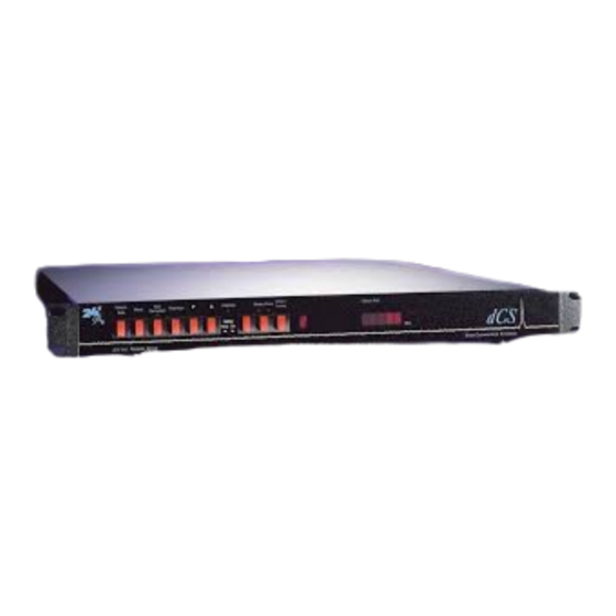
dCS 904
Analogue to Digital Converter
User Manual
Standard Software version 1.5x
P3D Software version 1.36
June 2000
© 1997, 1999, 2000 dCS Ltd
All rights reserved. Reproduction of this manual in any manner whatsoever,
1
without the written permission of dCS
is strictly forbidden. Additional copies of
this manual may be obtained from dCS.
Information contained in this manual is subject to change without notice, and
whilst it is checked for accuracy, no liabilities can be accepted for errors.
1
dCS Ltd is Data Conversion Systems Ltd. Company registered in the England no. 2072115
Download from Www.Somanuals.com. All Manuals Search And Download.
Advertisement
Chapters
Table of Contents

Related Manuals for DCS 904


Summary of Contents for DCS 904
- Page 1 Information contained in this manual is subject to change without notice, and whilst it is checked for accuracy, no liabilities can be accepted for errors. dCS Ltd is Data Conversion Systems Ltd. Company registered in the England no. 2072115 Download from Www.Somanuals.com. All Manuals Search And Download.
-
Page 2: Product Features
904 User Manual Manual for Software Version 1.5x and 1.36 dCS Ltd June 2000 RODUCT EATURES Formats • DSD, and PCM from 192 kS/s down to 32 kS/s • Data formats supported are: AES/EBU (XLR and BNC), Dual AES (XLR),... - Page 3 904 User Manual Manual for Software Version 1.5x and 1.36 dCS Ltd June 2000 Page 3 Manual part no: DOC135904 iss 2B2 135904ma2b2.pdf file available from website Contact on + 44 1799 531 999 email to: more@dcsltd.co.uk (inside the UK replace + 44 with 0) web site: www.dcsltd.co.uk...
-
Page 4: Table Of Contents
Ltd June 2000 CONTENTS Product Features ....................2 CONTENTS ......................4 About this Manual Using Your dCS 904 For The First Time ............6 Product Overview What’s in the Box? Mains Voltages Installing Unit in a Rack Getting Started The Hardware – Controls and Connectors.............10... -
Page 5: About This Manual
904 User Manual Manual for Software Version 1.5x and 1.36 dCS Ltd June 2000 Internal Device Error Codes System Messages and Error Codes Trouble Shooting Your System dCS Support.......................77 I wish ..If You Need More Help Other Information Indexes and Software Version Numbers............79... -
Page 6: Using Your Dcs 904 For The First Time
Remote software Mains Voltages The dCS 904 is shipped with its mains voltage preset for operation in the destination country. The voltage is not intended to be changed by the user. If it needs to be changed, contact your dealer or dCS. -
Page 7: Installing Unit In A Rack
904 User Manual Manual for Software Version 1.5x and 1.36 dCS Ltd June 2000 Installing Unit in a Rack The unit is supplied with 19" rack mount ears fitted. If it is to be mounted in a 19" rack, the ears supplied may be used to locate it in the rack and stop the unit sliding forward –... -
Page 8: Getting Started
Press the Output Format button (right hand end) to get the format you want. Set up like this, the dCS 904 will operate in Master mode, and the system it is connected to will (have to) lock to it. You should have audio. - Page 9 904 User Manual Manual for Software Version 1.5x and 1.36 dCS Ltd June 2000 Page 9 Manual part no: DOC135904 iss 2B2 135904ma2b2.pdf file available from website Contact on + 44 1799 531 999 email to: more@dcsltd.co.uk (inside the UK replace + 44 with 0) web site: www.dcsltd.co.uk...
-
Page 10: The Hardware - Controls And Connectors
904 User Manual Manual for Software Version 1.5x and 1.36 dCS Ltd June 2000 – C ARDWARE ONTROLS AND ONNECTORS Rear Panel CH1(L) CH2(R) Sensitivity Reference In Reference Out AES1 AES2 AES3 AES4 MAINS FUSE 2A(T) ON OFF PUSH... - Page 11 The underside of the unit will have a label on that contains a number such as 904 4B1 6B2 2A1 3A2 12345. This is the serial number, but it also contains vital configuration information. We will need this number (all of it) to give you support over the phone, or to ship you software updates.
-
Page 12: Front Panel
“digital” sound due to the abrupt chopping off of the low level signal information. To avoid this, the dCS 904 allows proper truncation of the data and uses Noise Shaping to maintain low level performance. See the section on “Word Length... - Page 13 904 User Manual Manual for Software Version 1.5x and 1.36 dCS Ltd June 2000 Pressing the Word Length button repeatedly cycles the word length through the sequence: 24, 23, 22, 21, 20, 19, 18, 17, 16, 24, etc. The Word Length is briefly shown on the main display, and if a setting other than the maximum is set, the word length LED (above the button) lights.
- Page 14 Ltd June 2000 The overload indication given by the dCS 904 is comprehensive. The detection circuitry monitoring the digital filter does not simply check the final output word but all the data from which the output word is formed. If any of these overload (this may not be apparent from the output data), an overload is flagged.
-
Page 15: Table 1 Reference Clock And Sample Rates
Once slaved, the unit can internally multiply the reference input sample rate by 2 or 4, if required, by pressing the Multiplier button. The Master Clock must be set to a suitable sample rate: dCS 904 Sample Rate (kS/s) Master Clock Sample Rate (kS/s) 44.1 44.1 or 88.2 or 176.4 48 or 96 or 192 88.2... - Page 16 AES clock). This is controlled by the menu item for P3D optioned units). See page 20. dCS equipment encodes messaging into the various data streams to enable receiving equipment to tell what is going on, and to decide which wire is which, in the unlikely event of user wiring errors.
- Page 17 If the display is completely blank for any significant period, try switching off for 10 seconds then switching on again. If this does not solve the problem, contact your distributor or dCS. The display is also used for Menu options.
-
Page 18: The Software - The Menu
OFTWARE Overview The dCS 904 has many other functions that either need to be accessed only occasionally, or are informative in nature. These functions can be accessed either by the Remote software, running on a PC and connected to the unit by an RS-232 link - or (in most cases) by the Menu. -
Page 19: The Menu Sequence
904 User Manual Manual for Software Version 1.5x and 1.36 dCS Ltd June 2000 The Menu Sequence To access the Function Menu, hold down the Menu Step button and press the Menu Set button. To step through the Menu items, press the Menu Step button repeatedly. -
Page 20: Menu Items
904 User Manual Manual for Software Version 1.5x and 1.36 dCS Ltd June 2000 Menu Items Issue Displays the software issue when is pressed. Filt Selects one of several anti-alias filter responses. The filters should be evaluated Filt1 by ear. - Page 21 AES3 data streams in the appropriate manner. Contact dCS for further details If DSD is packed into AES3 links (DSD 4 or P3D), the dCS 904 sets the Non Audio flag in the AES3 message, so that a DAC further downstream will mute if...
- Page 22 Fahrenheit and Celsius. See section “Operating Conditions” on page 63 Phone dCS telephone number scrolls across the display Part The control board part number (version) scrolls along the display. S-No The control board serial number scrolls along the display. You will need something to write this on, if you call us for help.
- Page 23 904 User Manual Manual for Software Version 1.5x and 1.36 dCS Ltd June 2000 Ref In Sets the mode of the AES Reference In/Out connectors. The options are: Loop Loops the input through to the output, with no termination resistor (termination is then about 1kohm, so several units can be daisy chained).
-
Page 24: Using A Dcs 904 To Output Dsd
AES 3 AES 4 Mains Fuse (2AT) External Loop Sync Remote Figure 5 – Syncing a dCS 904 to a Master Clock A-SL do this: Make sure (Autoslave) is is set to Page 24 Manual part no: DOC135904 iss 2B2 135904ma2b2.pdf file available from website... -
Page 25: Storing Dsd On An 8 Track 16/44.1 Pcm Recorder
Figure 7 – Six channel set up without a Master Clock Ref In option set to Int. The middle one The top dCS 904 needs to have its should be set to Loop, and the bottom one should be set to Loop.t. -
Page 26: Storing 6 Channel Dsd On A 24 Track 16/44.1 Pcm Recorder
Figure 8 – Six channel DSD recording on a 24 track 16/44.1 kS/s recorder DSD 4 Make sure is turned on, from the menu. The top dCS 904 needs to have Ref In option set to Int. The middle one should be set to Loop, and the Loop.t... -
Page 27: Operating Several Units On One Remote Chain
904 User Manual Manual for Software Version 1.5x and 1.36 dCS Ltd June 2000 Operating Several Units on One Remote Chain CH1(L) CH2(R) Sensitivity Reference In Reference Out AES1 AES2 AES3 AES4 MAINS FUSE 2A(T) ON OFF PUSH PUSH... -
Page 28: Channel P3D Dsd Set Up With Monitoring
PCM Meter feed for Ch 7 & 8 Figure 10 – 8 Channel P3D DSD Set Up Four P3D capable dCS 904 units and a Master Clock can be used as above to give 8 channel DSD with additional simultaneous AES3 PCM outputs to give level monitoring on PCM equipment. - Page 29 904 User Manual Manual for Software Version 1.5x and 1.36 dCS Ltd June 2000 Page 29 Manual part no: DOC135904 iss 2B2 135904ma2b2.pdf file available from website Contact on + 44 1799 531 999 email to: more@dcsltd.co.uk (inside the UK replace + 44 with 0) web site: www.dcsltd.co.uk...
-
Page 30: Dcs 904 Technical Information
NFORMATION Anti Alias Filtering The dCS 904 offers a choice of 4 anti-alias filters on most sample rates. These filters affect the ultrasonic part of the spectrum - 20 kHz upwards. The unit is an ADC, with an output data rate set by the interface standard used. -
Page 31: Clocking
The highest quality clocks that are available are crystals, so we use these. In Master mode, the dCS 904 uses one of two on-board voltage controlled crystal oscillators (VCXOs) as clock sources – one for 48 kS/s related outputs and one for 44.1 kS/s related outputs. -
Page 32: Dsd
(well above 100 kHz) although at these ultrsonic frequencies noise is also present. The dCS 904 offers a number of different DSD modulators – as Filter options. All the modulators in have the same signal frequency response. They differ in the way they shape the out of band Q noise, and in how far they suppress the in band Q noise. -
Page 33: Table 4 - Dsd Filter Performance
Figure 11, on page 34. The dCS 904 complies with this standard. If the unit is set up for full scale PCM, and then switched to a DSD format, the levels will be correctly set to meet SACD standards. -
Page 34: Figure 11 - Dsd, Showing Dsd Full Scale
904 User Manual Manual for Software Version 1.5x and 1.36 dCS Ltd June 2000 DSD Format, showing Full Scale Signal dCS 972 SW v1.54 -0.5 -1.5 Time (usecs) Figure 11 – DSD, showing DSD full scale DSD has only two levels – printer artefacts make it look like more... -
Page 35: Figure 13 - Dsd Output, Filter Responses (Integrated Q Noise)
904 User Manual Manual for Software Version 1.5x and 1.36 dCS Ltd June 2000 Integrated Q Noise for DSD Filters normalised for Full Scale DSD at 0dB 20.00 0.00 -20.00 -40.00 -60.00 -80.00 -100.00 -120.00 -140.00 -160.00 -180.00 1000 Frequency (kHz) Figure 13 –... -
Page 36: Figure 15 - Dsd Output, With Analogue And Q Spot Noise
904 User Manual Manual for Software Version 1.5x and 1.36 dCS Ltd June 2000 Power Spectrum, v1.50 ADC DSD filters Filt1 Filt2 32k FFT, H6 window, effective noise Filt3 bandwith per bin 200 Hz Filt4 Filt5 Filt6 Filt7 -100... -
Page 37: Sample Alignment
June 2000 Sample Alignment The dCS 904 aligns samples such that word clock out aligns with AES3 samples out, the rising edge of word clock aligning with the start of the first illegal code in the X,Z subframe preamble and the falling edge aligning with the start of the Y subframe preamble. -
Page 38: Figure 18 - Word Clock In To Word Clock Out, 96 Ks/S
904 User Manual Manual for Software Version 1.5x and 1.36 dCS Ltd June 2000 Figure 18 – Word Clock in to Word Clock out, 96 kS/s Figure 19 – Word Clock in to Word Clock out, 44.1 kS/s Page 38 Manual part no: DOC135904 iss 2B2 135904ma2b2.pdf file available from website... -
Page 39: Figure 20 - Aes3 In To Aes3 Out, 96 Ks/S
40 nsecs. Input is at the top of the displays, output is at the bottom. Signals are at the sockets on the dCS 904, and the unit was slaved to AES Ref In. Figure 20 – AES3 in to AES3 out, 96 kS/s Figure 21 –... -
Page 40: Figure 22 - Word Clock In To Aes3 Out, 96 Ks/S
904 User Manual Manual for Software Version 1.5x and 1.36 dCS Ltd June 2000 AES3 data out is also related to the phase of word clock in. The scope shots below were taken with the unit sync’d to Word Clock. -
Page 41: Noise Shaping
Manual for Software Version 1.5x and 1.36 dCS Ltd June 2000 Noise Shaping The dCS 904 uses noise shaping that is optimised to the F weighting curve . It does not affect signal frequency or transient response, but shapes the frequency response of errors (Q noise, or truncation errors) so that they fall as much as possible in the less sensitive part of the spectrum. -
Page 42: Figure 24 - 1 St Order Noise Shapers Implemented On Dcs 904
48 kS/s 88.2 kS/s 96 kS/s 176.4 kS/s 192 kS/s Frequency (kHz) Figure 24 – 1 Order Noise Shapers implemented on dCS 904 3rd Order Noise Shape Plots 32 kS/s 44.1 kS/s 48 kS/s 88.2 kS/s 96 kS/s 176.4 kS/s... -
Page 43: Figure 26 - 9 Th Order Noise Shapers Implemented On Dcs 904
Frequency (kHz) Figure 26 – 9 Order Noise Shapers implemented on dCS 904 The noise shaper plots above are all on the same vertical scales for easy comparison, and the vertical grid is approximately 1 bit per grid line. Note that for the audio band, 9 order noise shaping at 176.4 kS/s or 192 kS/s gives huge... -
Page 44: Digital Interface Specifications
904 User Manual Manual for Software Version 1.5x and 1.36 dCS Ltd June 2000 Digital Interface Specifications Input Output AES/EBU (AES3) Type Balanced, differential Impedance Ω Sensitivity (unloaded) 1 ~ 10 > 5 V pk-pk Maximum Wordlength bits Damage level >... -
Page 45: Analogue Input Specifications
904 User Manual Manual for Software Version 1.5x and 1.36 dCS Ltd June 2000 Analogue Input Specifications Balanced Inputs Type Balanced Format AES14 : 1992 Impedance kΩ kΩ CMRR 50 Hz >100 dB, spec 50 Hz >120 dB, typ 1 kHz >108... -
Page 46: Digital Data Formats Supported
“SDIF-2” page 50 for more details. DSD has, at the time of writing, no messaging structure over SDIF-2 or SDIF-3. Messaging for P3D is allowed for, but not defined yet. Contact dCS for more details. Page 46 Manual part no: DOC135904 iss 2B2 135904ma2b2.pdf file available from website... -
Page 47: Aes3 (Aes/Ebu) Format
DCS1 Destination: null For more information on the way dCS implement the AES3 system message to handle higher sample rates, see the Appendix to this manual. For the formal definition of the AES3 interface, see footnote , from the AES. -
Page 48: Figure 27 - Aes3 Format At 48 Ks/S Over 16 Metres
904 User Manual Manual for Software Version 1.5x and 1.36 dCS Ltd June 2000 Figure 27 – AES3 format at 48 kS/s over 16 metres Figure 28 – AES3 format at 48 kS/s over 94 metres Page 48 Manual part no: DOC135904 iss 2B2 135904ma2b2.pdf file available from website... -
Page 49: Figure 29 - Aes3 Format At 96 Ks/S Over 16 Metres
904 User Manual Manual for Software Version 1.5x and 1.36 dCS Ltd June 2000 Figure 29 – AES3 format at 96 kS/s over 16 metres Figure 30 – AES3 format at 96 kS/s over 94 metres Page 49 Manual part no: DOC135904 iss 2B2 135904ma2b2.pdf file available from website... -
Page 50: Figure 31 - Sdif-2 Pcm Format At 96 Ks/S
904 User Manual Manual for Software Version 1.5x and 1.36 dCS Ltd June 2000 SDIF-2 PCM Format The SDIF-2 interface is a 4 wire NRZ interface - so the DC level on each signal line may not be constant. It contains 20 bits of audio data and has a block structure of 256 stereo samples, rather than the 192 of AES/EBU. -
Page 51: Table 10 - Sdif-2 Message Table
Ltd June 2000 Figure 32 – SDIF-2 PCM format at 44.1 kS/s SDIF-2 Messaging The SDIF-2 message is given in the table following. The dCS 904 implementation sets all bits of the User message to "0". DESCRIPTION Definition Default... -
Page 52: Figure 33 - Dsd Using Sdif-2 Electrical Format
904 User Manual Manual for Software Version 1.5x and 1.36 dCS Ltd June 2000 DSD on SDIF-2 SDIF-2 can be used for DSD. The waveforms appear quite different to PCM format. However, they do produce transitions where the illegal code transitions were, and for this reason we advise against locking to the illegal transitions in SDIF-2. -
Page 53: Rs-232 Remote Control Interface
All commands available from the front panel (and a few others, dCS use only) of a unit can be remotely controlled using this approach. Each unit must have a unique ID (in the range 0 to 99) which must be set up by hand using the menu system on the front panel. - Page 54 The addressed receiving unit (ADC, DAC, DDC, Master Clock, etc) acknowledges within 50 msecs of the last transmitted byte in the transmit message. For some special cases (dCS use only, see “Special Commands and Protocols” below) commands do not acknowledge. If the checksum is incorrect the receiving unit will ignore the command, clear its buffer and will not acknowledge.
- Page 55 Address F1 hex (241 decimal), Command RS_ENABLE_DEBUG (19 decimal) ALL units on daisy chain react to command. Nothing acknowledges. This enables dCS debugging commands. This may result in unstable behaviour of the unit. Page 55 Manual part no: DOC135904 iss 2B2 135904ma2b2.pdf file available from website...
- Page 56 904 User Manual Manual for Software Version 1.5x and 1.36 dCS Ltd June 2000 Command Streams Example – a system of 9 units with ID’s set up as noted: Master Clock (ID 1), P3D compatible ADCs (ID 2, 3, 4 and 5), P3D compatible DACs (ID 6, 7, 8 and 9).
- Page 57 904 User Manual Manual for Software Version 1.5x and 1.36 dCS Ltd June 2000 Transmit -> [7][DSD_MODE], to change mode to PCM of unit 7 Responds -> [ACK 15 seconds][7], requested mode Transmit -> [8][DSD_MODE], to change mode to PCM of unit 8 Responds ->...
- Page 58 904 User Manual Manual for Software Version 1.5x and 1.36 dCS Ltd June 2000 Check Master Clock has changed frequency. If it has not go back to step Transmit -> [1][REQUEST_FS], request actual frequency Responds -> [ACK immediate][1], actual frequency The system is now set up with the Master Clock configured for 96k operation and the ADCs and DACs locked in PCM mode to 96k.
- Page 59 904 User Manual Manual for Software Version 1.5x and 1.36 dCS Ltd June 2000 Check DACs for mode change. This command allows the Transmitter to check the mode of the DACs. If a unit has not changed the transmitter should go back to step 8 and repeat the command.
- Page 60 904 User Manual Manual for Software Version 1.5x and 1.36 dCS Ltd June 2000 Command name Command Number of Parameters Parameters Byte Parameters Response Command 0 = do not automatically slave RS_AUTO_SLAVE 1 = automatically slave to a reference...
-
Page 61: Table 11 - Rs-232 Command Set
904 User Manual Manual for Software Version 1.5x and 1.36 dCS Ltd June 2000 Command name Command Number of Parameters Parameters Byte Parameters Response Command first parameter is terminator (AES) RS_REF_MODES 0 = unterminated 1 = terminated second is reference mode... -
Page 62: Power Consumption
June 2000 Power Consumption The dCS 904 has a linear power supply, and so power consumption changes as the mains voltage changes. The internal regulation is comparatively efficient for a linear supply, so these changes are kept to a minimum. Power consumption is independent of mains voltage selector switch setting. -
Page 63: Operating Conditions
Allowing 3 cms between units gives reasonable cooling. If in doubt, the easy test is – the dCS 904 is happy to work anywhere a human is. dCS 9xx EXCESS TEMPERATURE (Measured as dCS 954 ) Middle unit of 3, in box with "shelf plates"... -
Page 64: General Technical Information
904 User Manual Manual for Software Version 1.5x and 1.36 dCS Ltd June 2000 ENERAL ECHNICAL NFORMATION Word Length Reduction Word length reduction (truncation) causes an error signal to be added to the wanted signal. The error signal is usually referred to as “Q noise” or Quantisation noise –... -
Page 65: Table 12 - Dither And Noise Shaping Noise Powers
904 User Manual Manual for Software Version 1.5x and 1.36 dCS Ltd June 2000 possibly get away with – the amount that simple 16 bit truncation (16 bit Q noise) would give, if it were well behaved, which it is not. -
Page 66: Figure 35 - Noise Shaping And Dither Spectra
This seems to dCS to combine the worst of all worlds – the high noise floor in the 0-6 kHz area of straight dither, and the high total noise of noise shaping. -
Page 67: Figure 36 - Truncation Only Spectra
904 User Manual Manual for Software Version 1.5x and 1.36 dCS Ltd June 2000 Spectra of -90dB 24 bit sinewave truncated to 16 bits with dither options dCS 972 SW v1.54 44.1 kS/s sampling, 1.44 kHz input, 1024 point FFTs, H6 Window... -
Page 68: Options
904 units. If you are in any doubt, please contact your Distributor or dCS. In general, these will be carried out at dCS, because we have extensive test facilities and can verify the changes. - Page 69 904 User Manual Manual for Software Version 1.5x and 1.36 dCS Ltd June 2000 Page 69 Manual part no: DOC135904 iss 2B2 135904ma2b2.pdf file available from website Contact on + 44 1799 531 999 email to: more@dcsltd.co.uk (inside the UK replace + 44 with 0) web site: www.dcsltd.co.uk...
-
Page 70: Maintenance And Support
• no dust deposits build up to degrade performance. All parts are replaceable or upgradeable by dCS, for a period of at least five years from the date you purchased your unit. If your unit is damaged in some way, please contact your Distributor or dCS. -
Page 71: Software
EPROM installed internally. Using the RS-232 download is hands free, but takes about 40 mins per unit. With special software (contact dCS) multiple units can be daisy chained together so that one PC can update them all serially (overnight). -
Page 72: Hardware Update Or Calibration
Safety and Electrical Safety There are no user serviceable parts inside the dCS 904 and so there is no need to remove the covers, apart from front panel software updates. If for some reason you do: IMPORTANT! Disconnect from the mains before removing any covers or changing the fuse. - Page 73 904 User Manual Manual for Software Version 1.5x and 1.36 dCS Ltd June 2000 Page 73 Manual part no: DOC135904 iss 2B2 135904ma2b2.pdf file available from website Contact on + 44 1799 531 999 email to: more@dcsltd.co.uk (inside the UK replace + 44 with 0) web site: www.dcsltd.co.uk...
-
Page 74: Error Codes And Messages
HOOTING Error Codes and Messages The error codes reported by dCS 904 provide an effective means to diagnose the majority of problems that may be encountered in use - including problems with the overall system the unit operates in, internal device warnings and internal device failures. -
Page 75: Table 14 - System Error Codes
Table 14 - System Error Codes Trouble Shooting Your System If you experience difficulties when using your dCS 904, the following suggestions may help to resolve the problem. The unit fails to power up •... - Page 76 - typically 1, 2, 4 or 8 consecutive samples. There is some justification for this - single saturation events are not always audible. The dCS 904 flags their presence - it is up to the recording engineer to decide what to do about it.
-
Page 77: Table 15 - Dcs Phone Numbers
Our web site is: http://www.dcsltd.co.uk Other Information dCS produce technical notes from time to time, on issues related to ADCs. If you are interested in these, please do not hesitate to contact us, or check our web site. Page 77 Manual part no: DOC135904 iss 2B2 135904ma2b2.pdf file available from website... - Page 78 904 User Manual Manual for Software Version 1.5x and 1.36 dCS Ltd June 2000 Page 78 Manual part no: DOC135904 iss 2B2 135904ma2b2.pdf file available from website Contact on + 44 1799 531 999 email to: more@dcsltd.co.uk (inside the UK replace + 44 with 0) web site: www.dcsltd.co.uk...
- Page 79 904 User Manual Manual for Software Version 1.5x and 1.36 dCS Ltd June 2000 NDEXES AND OFTWARE ERSION UMBERS This manual is for standard software version 1.5x. and P3D unit software v1.36. v1.5x differs from v1.3x in having substantially improved DSD modulators, and in having a more friendly menu structure, with readback on current settings without having to change the settings.
-
Page 80: Figure 1- Rear Panel
Syncing Functions Test Generator Ease of Use CONTENTS ......................4 About this Manual Using Your dCS 904 For The First Time ............6 Product Overview What’s in the Box? Mains Voltages Installing Unit in a Rack Getting Started The Hardware – Controls and Connectors.............10... - Page 81 Offst Typical Applications..................24 Using a dCS 904 to output DSD Using a Master Clock to Sync a dCS 904 Storing DSD on an 8 track 16/44.1 PCM Recorder Six Channel PCM Set Up Storing 6 channel DSD on a 24 track 16/44.1 PCM Recorder...
- Page 82 The unit fails to slave to a Master Clock The unit slaves to Word Clock but not AES/EBU The Overload indicator will not go out External meter does not show overload, dCS 904 does. dCS Support.......................77 I wish ..If You Need More Help Other Information Indexes and Software Version Numbers............79...
- Page 83 Table 12 – Dither and Noise Shaping Noise Powers..........65 Table 13 - Internal Error Codes ................74 Table 14 - System Error Codes .................75 Table 15 – dCS Phone Numbers ................77 Page 83 Manual part no: DOC135904 iss 2B2 135904ma2b2.pdf file available from website...
- Page 84 Figure 3 – Menu Sequence ................19 Figure 4 – DSD output configuration ..............24 Figure 5 – Syncing a dCS 904 to a Master Clock ..........24 Figure 6 – Storing 2 channel DSD on an 8 track 16 bit 44.1 kS/s PCM recorder..................25...
- Page 85 904 User Manual Manual for Software Version 1.5x and 1.36 dCS Ltd June 2000 Keywords and Phrases ADC mode ..........14, 21 LED, ADC/Data ..........14 AES3, dual.........16, 46, 75 LED, Master ..........14 AES3, quad..........16, 76 LED, mute ............. 12 anti-alias filtering..........30...
- Page 86 904 User Manual Manual for Software Version 1.5x and 1.36 dCS Ltd June 2000 Reference, active...........15 Temperature, operating ........ 63 Reference, input ..........10 Temperature, rise in rack ......63 Reference, termination ........10 Termination, reference input ......10 RS-232..........11, 53, 71 RS-232, address........22, 27...
- Page 87 Free Manuals Download Website h p://myh66.com h p://usermanuals.us h p://www.somanuals.com h p://www.4manuals.cc h p://www.manual-lib.com h p://www.404manual.com h p://www.luxmanual.com h p://aubethermostatmanual.com Golf course search by state h p://golfingnear.com Email search by domain h p://emailbydomain.com Auto manuals search h p://auto.somanuals.com TV manuals search h p://tv.somanuals.com...
Need help?
Do you have a question about the 904 and is the answer not in the manual?
Questions and answers