Table of Contents
Advertisement
Quick Links
dCS 954
Digital to Analogue Converter
User Manual
Standard software version 1.5x
P3D software version 1.36
June 2000
© 1997, 1999, 2000 dCS Ltd
All rights reserved. Reproduction of this manual in any manner whatsoever,
1
without the written permission of dCS
is strictly forbidden. Additional copies of
this manual may be obtained from dCS.
Information contained in this manual is subject to change without notice, and
whilst it is checked for accuracy, no liabilities can be accepted for errors.
1
dCS Ltd is Data Conversion Systems Ltd. Company registered in England, UK, no. 2072115
Advertisement
Chapters
Table of Contents
Troubleshooting

Related Manuals for DCS 954


Summary of Contents for DCS 954
-
Page 1: User Manual
Information contained in this manual is subject to change without notice, and whilst it is checked for accuracy, no liabilities can be accepted for errors. dCS Ltd is Data Conversion Systems Ltd. Company registered in England, UK, no. 2072115... -
Page 2: Dcs Ltd June
954 User Manual Manual for Standard Software Version 1.5x dCS Ltd June 2000 Page 2 Manual part no: DOC136954 iss 2B1 file 135954ma2b1.pdf available from website Contact on + 44 1799 531 999 email to: more@dcsltd.co.uk (inside the UK replace + 44 with 0) -
Page 3: Product Features
954 User Manual Manual for Standard Software Version 1.5x dCS Ltd June 2000 RODUCT EATURES Formats • DSD, and PCM from 192 kS/s down to 32 kS/s • Data formats supported are: AES/EBU (XLR and BNC), Dual AES (XLR),... -
Page 4: Table Of Contents
Ltd June 2000 CONTENTS Product Features ....................3 CONTENTS ......................4 About this Manual Using Your dCS 954 For The First Time ............6 Product Overview What’s in the Box? Mains Voltages Installing Unit in a Rack Getting Started The Hardware – Controls and Connectors.............10... -
Page 5: About This Manual
954 User Manual Manual for Standard Software Version 1.5x dCS Ltd June 2000 Safety and Electrical Safety TroubleShooting ....................76 Error Codes and Messages Internal Device Error Codes System Messages and Error Codes Trouble Shooting Your System dCS Support.......................80 I wish .. -
Page 6: Using Your Dcs 954 For The First Time
Remote software Mains Voltages The dCS 954 is shipped with its mains voltage preset for operation in the destination country. The voltage is not intended to be changed by the user. If it needs to be changed, contact your dealer or dCS. -
Page 7: Installing Unit In A Rack
954 User Manual Manual for Standard Software Version 1.5x dCS Ltd June 2000 Installing Unit in a Rack The unit is supplied with 19" rack mount ears fitted. If it is to be mounted in a 19" rack, the ears supplied may be used to locate it in the rack and stop the unit sliding forward –... -
Page 8: Getting Started
You should have audio. Note that the balanced and unbalanced outputs are active simultaneously on the dCS 954 and may both be connected to external equipment simultaneously if required. Now you will need to familiarise yourself with how the front panel controls and the menu system work. - Page 9 954 User Manual Manual for Standard Software Version 1.5x dCS Ltd June 2000 Page 9 Manual part no: DOC136954 iss 2B1 file 135954ma2b1.pdf available from website Contact on + 44 1799 531 999 email to: more@dcsltd.co.uk (inside the UK replace + 44 with 0)
-
Page 10: The Hardware - Controls And Connectors
954 User Manual Manual for Standard Software Version 1.5x dCS Ltd June 2000 – C ARDWARE ONTROLS AND ONNECTORS Rear Panel CH1(L) CH2(R) Sensitivity Reference In Reference Out AES1 AES2 AES3 AES4 MAINS FUSE 2A(T) ON OFF PUSH PUSH... - Page 11 The underside of the unit will have a label on that contains a number such as 954 4B1 6B2 2A1 3A2 12345. This is the serial number, but it also contains vital configuration information. We will need this number (all of it) to give you support over the phone, or to ship you software updates.
-
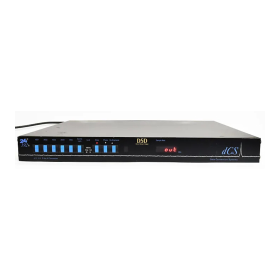
Page 12: Front Panel
Data Conversion Systems Figure 3 – Front Panel The dCS 954 uses a combination of front panel buttons for frequently changed functions and a step through menu for features you might set and forget. AES1, AES2, AES3, AES4 & BNC Menu Step The 5 buttons on the left side of the front panel select the active input(s). -
Page 13: Active Input Button
CD players) can show large timing transients as the movement occurs, which can upset the dCS 954, causing intermittent data errors or muting. To cater for this situation, the dCS 954 allows two PLL settings – fine lock and coarse lock. If the problem arises, pressing the... -
Page 14: Table 1 - Phase Leds And Channel Phasing
954 User Manual Manual for Standard Software Version 1.5x dCS Ltd June 2000 Mute Menu Set Mute button is dual function – on its own (blue type on the front panel), it mutes and unmutes the analogue outputs when the unit is locked to a source. -
Page 15: Table 2 - Emphasis Indication, Low Sample Rates
The unit implements CCITT J17 De-Emphasis. De-Emphasis disabled. Table 2 – Emphasis Indication, low sample rates dCS recommend setting the unit to Automatic unless there is an error in the De-Emphasis message in the incoming data stream. For Menu operation as the button, see the section “The Software –... -
Page 16: Reference, Input
If the display is completely blank for any significant period, try switching off for 10 seconds then switching on again. If this does not solve the problem, contact your distributor or dCS. The display is also used for Menu options. Page 16 Manual part no: DOC136954 iss 2B1 file 135954ma2b1.pdf available from website... - Page 17 954 User Manual Manual for Standard Software Version 1.5x dCS Ltd June 2000 Page 17 Manual part no: DOC136954 iss 2B1 file 135954ma2b1.pdf available from website Contact on + 44 1799 531 999 email to: more@dcsltd.co.uk (inside the UK replace + 44 with 0)
-
Page 18: The Software - The Menu
OFTWARE Overview The dCS 954 has many other functions that either need to be accessed only occasionally, or are informative in nature. These functions can be accessed either by the Remote software, running on a PC and connected to the unit by an RS-232 link - or (in most cases) by the Menu, via the front panel. -
Page 19: The Menu Sequence
954 User Manual Manual for Standard Software Version 1.5x dCS Ltd June 2000 The Menu Sequence To access the Function Menu, hold down the Menu Step button and press the Menu Set button. (The Menu Step button corresponds to the selected input - LED bright or flashing.) To step through the Menu items, press the Menu Step button repeatedly. -
Page 20: Menu Items
954 User Manual Manual for Standard Software Version 1.5x dCS Ltd June 2000 Menu Items Issue Displays the software issue when is pressed. Selects DSD mode. When on and locked, the unit displays “dSd”. This mode takes about 15 seconds to load, during which time the menu cannot be used. - Page 21 Ltd June 2000 IMPORTANT! If the Non Audio flag is stripped by the recorder and the dCS 954 is not set to DSD mode, it will accept DSD data as AES3 PCM and will output potentially damaging full scale noise.
- Page 22 If the main signal fails, the unit will automatically switch to the backup. Or, if you wish the dCS 954 to just play whatever you plug into it, and not worry about A-Sel to On.
-
Page 23: Reference, Termination
954 User Manual Manual for Standard Software Version 1.5x dCS Ltd June 2000 If the input format is set to Single, Dual or Quad AES format, the unit will ignore the message flags and group the AES inputs accordingly. -
Page 24: Tone Generator
954 User Manual Manual for Standard Software Version 1.5x dCS Ltd June 2000 Tone Tone (Tone Generator). This controls an internal Generator, whose level and frequency can be adjusted. Pressing enters a submenu, which accesses the following functions: Level The output level in dB0. -
Page 25: Figure 5 - In-Phase Sys Waveform
954 User Manual Manual for Standard Software Version 1.5x dCS Ltd June 2000 Figure 5 – In-phase Sys waveform Referring to Figure 5, if the triangular sections point up, that channel is in phase. A triangular section pointing up with a rectangular block on its left side indicates left channel. - Page 26 Quad AES). Swapped wires causes a display like 1243 (AES3 & swapped). The checking relies on correct messaging and may not work with non-dCS equipment. Filt (Filter). Selects one of several anti-image filter responses. The filters should Filt1 be evaluated by ear.
-
Page 27: Clk Out
Volume. The change accelerates if a button is held down. The range is 0dB to –20dB. Phone dCS telephone number scrolls across the display. Facs dCS fax number scrolls across the display Part The control board part number (version) scrolls along the display. - Page 28 954 User Manual Manual for Standard Software Version 1.5x dCS Ltd June 2000 S-No The control board serial number scrolls along the display. You will need something to write this on, if you call us for help. Flip channels). Normally set to Off. If you find the Left and Right outputs from...
- Page 29 954 User Manual Manual for Standard Software Version 1.5x dCS Ltd June 2000 Page 29 Manual part no: DOC136954 iss 2B1 file 135954ma2b1.pdf available from website Contact on + 44 1799 531 999 email to: more@dcsltd.co.uk (inside the UK replace + 44 with 0)
-
Page 30: Using A Dcs 954 For Dsd
Unbalanced Balanced - or - outputs outputs To pre or power amplifier Figure 8 – Syncing a dCS 954 to a Master Clock RefCl. do this: in the menu to do this: Select the required input(s), then press the button as well. -
Page 31: Replaying Dsd From An 8 Track 16/44.1 Pcm Recorder
RS-232 address to be different. They can then be identified, and grouped, in the remote window. A mixture of dCS unit types may be used. “Remote In & Out“ on page 11 for cable details, and “RS-232 Remote... -
Page 32: Six Channel Pcm Set Up
To pre or power amplifier Figure 11 – Six channel set up Ref In option set to Route, the middle do this: The top dCS 954 needs to have its Loop Loop.t. one to and the bottom one to The units self align quite accurately (see section “Sample... -
Page 33: Replaying 6 Channel Dsd From A 24 Track 16/44.1 Pcm Recorder
Figure 12 – Replaying a 6 channel DSD recording from a 24 track 16/44.1 recorder Ref In option set to Route, the middle do this: The top dCS 954 needs to have its Loop Loop.t. one to and the bottom one to... -
Page 34: Replaying 8 Channel P3D Dsd
954 User Manual Manual for Standard Software Version 1.5x dCS Ltd June 2000 Replaying 8 Channel P3D DSD d C S 954 CH1(L) CH2(R) Sensitivity Reference In Reference Out AES1 AES2 AES3 AES4 MAINS FUSE 2A(T) ON OFF PUSH... -
Page 35: Upsampling A Cd
IMPORTANT! DO NOT lock the dCS 954 to the dCS 992 or the audio output will be full scale noise! The Master Clock is optional – it helps reduce jitter. If you don’t have a Master... -
Page 36: Converting Quad Aes To Single Aes
954 User Manual Manual for Standard Software Version 1.5x dCS Ltd June 2000 Converting Quad AES to Single AES Quad AES 192kS/s d C S 954 CH1(L) CH2(R) Sensitivity Reference In Reference Out AES1 AES2 AES3 AES4 MAINS FUSE 2A(T) ON OFF... -
Page 37: Replaying 24/192 From 2 Nagra-D Recorders
Quad AES 24/192 recordings split between 2 tapes may be played back as shown. The 2 Nagra-D recorders must be fitted with special hardware and software to achieve this – contact Nagra for details. The dCS 954 allows for small timing discrepancies between the AES1/2 pair and the AES3/4 pair. -
Page 38: Dcs 954 Technical Information
NFORMATION Anti Image Filtering The dCS 954 offers a choice of 4 anti-image filters on most sample rates. These filters affect the ultrasonic part of the spectrum - 20 kHz upwards. The unit is a DAC, with an output data rate set by the interface standard used. -
Page 39: Clocking
The highest quality clocks that are available are crystals, so we use these. The dCS 954 uses one of two on-board voltage controlled crystal oscillators (VCXOs) as a clock source – one for 48 kS/s related outputs and one for 44.1 kS/s related outputs. -
Page 40: Dsd
954 User Manual Manual for Standard Software Version 1.5x dCS Ltd June 2000 DSD is a single bit very high sample rate (2.822 MS/s) format, where the single bit words are heavily noise shaped to push noise energy above the audio band. -
Page 41: Sample Alignment
June 2000 Sample Alignment The dCS 954 aligns samples such that Word Clock Out aligns with AES3 samples out (Reference Out), the rising edge of Word Clock Out aligning with the start of the first illegal code in the X,Z subframe preamble and the falling edge aligning with the start of the Y subframe preamble. -
Page 42: Figure 21 - Word Clock In To Word Clock Out, 96 Ks/S
954 User Manual Manual for Standard Software Version 1.5x dCS Ltd June 2000 When Word Clock In is used as a sync source, in and out are related as below. The lower waveform is the output, the upper one is the input. The misalignment is less than about 40ns. -
Page 43: Figure 23 - Aes3 In To Aes3 Out, 96 Ks/S
AES3 input is used as a sync source. The alignment is better than 40ns. Input is at the top of the displays, output is at the bottom. Signals are at the sockets on the dCS 954, the unit was slaved to AES1... -
Page 44: Figure 24 - Aes3 In To Aes3 Out, 44.1 Ks/S
954 User Manual Manual for Standard Software Version 1.5x dCS Ltd June 2000 Figure 24 – AES3 in to AES3 out, 44.1 kS/s AES3 Reference Out is also related to the phase of Clk In. The scope shots below were taken with the unit sync’d to Clk In Figure 25 –... -
Page 45: Digital Interface Specifications
954 User Manual Manual for Standard Software Version 1.5x dCS Ltd June 2000 Digital Interface Specifications Input Output AES/EBU (AES3) Type Balanced, differential Impedance Ω Sensitivity (unloaded) 1 ~ 10 V pk-pk Maximum Wordlength bits Damage level > 20... -
Page 46: Analogue Interface Specifications
954 User Manual Manual for Standard Software Version 1.5x dCS Ltd June 2000 Analogue Interface Specifications Balanced Outputs Type Balanced, semi-floating Format AES14 : 1992 Source Impedance < 3 Ω (20Hz - 20kHz) Maximum Load Ω Noise, unweighted < -110 (20Hz –... -
Page 47: Frequency Response
954 User Manual Manual for Standard Software Version 1.5x dCS Ltd June 2000 Frequency Response The overall frequency response is determined by the sample rate, the digital filter and the analogue filter. If imaging is to be avoided, all filters must cut-off before Fs/2 is reached, with a margin to allow for sufficient attenuation to be reached to effectively eliminate Nyquist images. -
Page 48: Group Delay
Ltd June 2000 Group Delay The group delay for a dCS 904 and dCS 954 ADC and DAC were measured, at different sample rates. The results were as below (they are valid for software up to 1.5x): Filter 1... -
Page 49: Aes3 (Aes/Ebu) Format
DCS1 Destination: null For more information on the way dCS implement the AES3 system message to handle higher sample rates, see the Appendix to this manual. For the formal definition of the AES3 interface, see footnote , from the AES. -
Page 50: Figure 28 - Aes3 Format At 48 Ks/S Over 16 Metres
954 User Manual Manual for Standard Software Version 1.5x dCS Ltd June 2000 Figure 28 – AES3 format at 48 kS/s over 16 metres Page 50 Manual part no: DOC136954 iss 2B1 file 135954ma2b1.pdf available from website Contact on + 44 1799 531 999 email to: more@dcsltd.co.uk... -
Page 51: Figure 29 - Aes3 Format At 48 Ks/S Over 94 Metres
954 User Manual Manual for Standard Software Version 1.5x dCS Ltd June 2000 Figure 29 – AES3 format at 48 kS/s over 94 metres Figure 30 – AES3 format at 96 kS/s over 16 metres Figure 31 – AES3 format at 96 kS/s over 94 metres... -
Page 52: Sdif-2
954 User Manual Manual for Standard Software Version 1.5x dCS Ltd June 2000 SDIF-2 PCM Format The SDIF-2 interface is a 4 wire NRZ interface - so the DC level on each signal line may not be constant. It contains 20 bits of audio data and has a block structure of 256 stereo samples, rather than the 192 of AES/EBU. -
Page 53: Table 11 - Sdif-2 Messages
954 User Manual Manual for Standard Software Version 1.5x dCS Ltd June 2000 Figure 32 – SDIF-2 PCM format at 96 kS/s Figure 33 – SDIF-2 PCM format at 44.1 kS/s SDIF-2 Messaging The SDIF-2 message details are defined in the table following. -
Page 54: Figure 34 - Dsd Using Sdif-2 Electrical Format
954 User Manual Manual for Standard Software Version 1.5x dCS Ltd June 2000 DSD on SDIF-2 An SDIF-2 interface can be used for DSD. The waveforms appear quite different to PCM format. However, they do produce transitions where the illegal code transitions were, and for this reason we advise against locking to the illegal transitions in SDIF-2. -
Page 55: P3D Behaviour
Bit Error Rates The bit error rate (BER) for a dCS 904/dCS 954 running P3D is below 5x10 , (0 errors over 64 hours). The same error rate is likely to hold for all AES3 type formats. -
Page 56: Rs-232 Remote Control Interface
All commands available from the front panel (and a few others, dCS use only) of a unit can be remotely controlled using this approach. Each unit must have a unique ID (in the range 0 to 99) which must be set up by hand using the menu system on the front panel. - Page 57 The addressed receiving unit (ADC, DAC, DDC, Master Clock, etc) acknowledges within 50 msecs of the last transmitted byte in the transmit message. For some special cases (dCS use only, see “Special Commands and Protocols” below) commands do not acknowledge. If the checksum is incorrect the receiving unit will ignore the command, clear its buffer and will not acknowledge.
- Page 58 Address F1 hex (241 decimal), Command RS_ENABLE_DEBUG (19 decimal) ALL units on daisy chain react to command. Nothing acknowledges. This enables dCS debugging commands. This may result in unstable behaviour of the unit. Page 58 Manual part no: DOC136954 iss 2B1 file 135954ma2b1.pdf available from website...
- Page 59 954 User Manual Manual for Standard Software Version 1.5x dCS Ltd June 2000 Command Streams Example – a system of 9 units with ID’s set up as noted: Master Clock (ID 1), P3D compatible ADCs (ID 2, 3, 4 and 5), P3D compatible DACs (ID 6, 7, 8 and 9).
- Page 60 954 User Manual Manual for Standard Software Version 1.5x dCS Ltd June 2000 Responds -> [ACK 15 seconds][7], requested mode Transmit -> [8][DSD_MODE], to change mode to PCM of unit 8 Responds -> [ACK 15 seconds][8], requested mode Transmit -> [9][DSD_MODE], to change mode to PCM of unit 9 Responds ->...
-
Page 61: Pcm
954 User Manual Manual for Standard Software Version 1.5x dCS Ltd June 2000 Transmit -> [1][REQUEST_FS], request actual frequency Responds -> [ACK immediate][1], actual frequency The system is now set up with the Master Clock configured for 96k operation and the ADCs and DACs locked in PCM mode to 96k. - Page 62 954 User Manual Manual for Standard Software Version 1.5x dCS Ltd June 2000 Transmit -> [8][REQUEST_DSD_MODE] Response -> [ACK immediate][8], actual mode Transmit -> [9][REQUEST_DSD_MODE] Response -> [ACK immediate][9], actual mode Check ADCs for mode change. This command allows the Transmitter to check the mode of the ADCs.
-
Page 63: Generator, Frequency
954 User Manual Manual for Standard Software Version 1.5x dCS Ltd June 2000 Command name Command Number of Parameters Parameters Byte Parameters Response Command 0 = do not automatically slave RS_AUTO_SLAVE 1 = automatically slave to a reference input... -
Page 64: Table 12 - Rs-232 Command Set
954 User Manual Manual for Standard Software Version 1.5x dCS Ltd June 2000 Command name Command Number of Parameters Parameters Byte Parameters Response Command first parameter is terminator (AES) RS_REF_MODES 0 = unterminated 1 = terminated second is reference mode... -
Page 65: Power Consumption
June 2000 Power Consumption The dCS 954 has a linear power supply, and so power consumption changes as the mains voltage changes. The internal regulation is comparatively efficient for a linear supply, so these changes are kept to a minimum. Power consumption is independent of mains voltage setting. -
Page 66: Operating Conditions
Allowing 3 cms between units gives reasonable cooling. If in doubt, the easy test is – the dCS 954 is happy to work anywhere a human is. dCS 9xx EXCESS TEMPERATURE (Measured as dCS 954 ) Middle unit of 3, in box with "shelf plates"... - Page 67 954 User Manual Manual for Standard Software Version 1.5x dCS Ltd June 2000 Page 67 Manual part no: DOC136954 iss 2B1 file 135954ma2b1.pdf available from website Contact on + 44 1799 531 999 email to: more@dcsltd.co.uk (inside the UK replace + 44 with 0)
-
Page 68: General Technical Information
(storage drives, for example), these can be many hundreds of nsecs, and if one goes below 1 Hz, they get worse. Because of these types of issue, dCS use a bandwidth of around 5 Hz for our PLLs in fine lock. - Page 69 954 User Manual Manual for Standard Software Version 1.5x dCS Ltd June 2000 the FIFO has to be significantly filled at all times, which is the same a delay in the signal path. A bit error rate measurement based on this approach has shown rates with an...
-
Page 70: Options
954 units. If you are in any doubt, please contact your Distributor or dCS. In general, these will be carried out at dCS, because we have extensive test facilities and can verify the changes. - Page 71 954 User Manual Manual for Standard Software Version 1.5x dCS Ltd June 2000 Page 71 Manual part no: DOC136954 iss 2B1 file 135954ma2b1.pdf available from website Contact on + 44 1799 531 999 email to: more@dcsltd.co.uk (inside the UK replace + 44 with 0)
-
Page 72: Maintenance And Support
• no dust deposits build up to degrade performance. All parts are replaceable or upgradeable by dCS, for a period of at least five years from the date you purchased your unit. If your unit is damaged in some way, please contact your Distributor or dCS. -
Page 73: Software
EPROM installed internally. Using the RS-232 download is hands free, but takes about 40 mins per unit. With special software (contact dCS) multiple units can be daisy chained together so that one PC can update them all serially (overnight). -
Page 74: Hardware Update Or Calibration
Safety and Electrical Safety There are no user serviceable parts inside the dCS 954 and so there is no need to remove the covers, apart from front panel software updates. If for some reason you do: IMPORTANT! Disconnect from the mains before removing any covers or changing the fuse. -
Page 75: Dcs Ltd June
954 User Manual Manual for Standard Software Version 1.5x dCS Ltd June 2000 Page 75 Manual part no: DOC136954 iss 2B1 file 135954ma2b1.pdf available from website Contact on + 44 1799 531 999 email to: more@dcsltd.co.uk (inside the UK replace + 44 with 0) -
Page 76: Troubleshooting
HOOTING Error Codes and Messages The error codes and messages reported by dCS 954 provide an effective means to diagnose the majority of problems that may be encountered in use - including problems with the overall system the unit operates in, internal device warnings and internal device failures. -
Page 77: System Messages And Error Codes
CRC data integrity check (see page 55) Table 14 – System Error Codes Trouble Shooting Your System If you experience difficulties when using your dCS 954, the following suggestions may help to resolve the problem. The unit fails to power up •... -
Page 78: Ddc Mode
954 User Manual Manual for Standard Software Version 1.5x dCS Ltd June 2000 The unit fails to respond to the controls • While locking to a source or changing some settings (e.g. Filter), the microcontroller inside the unit is busy and will not respond to new commands for a few seconds. -
Page 79: Bnc Button
• Connect a different piece of digital equipment to test the locking capability of the unit. If the condition persists, contact your Distributor or dCS. The unit slaves to Word Clock but not AES Reference •... -
Page 80: Dcs Support
We value our customers, and we want to make products that do what you want. If You Need More Help Contact dCS. Our office hours are 8:00 am to about 7:00 pm, Monday to Friday, UK time (UTC in summer, or UTC + 1hr in winter). Contact us by phone or fax... -
Page 81: Indexes And Software Version Numbers
954 User Manual Manual for Standard Software Version 1.5x dCS Ltd June 2000 NDEXES AND OFTWARE ERSION UMBERS This manual is for standard software version 1.5x and P3D unit software v1.36. v1.5x differs from earlier standard software v1.3x and P3D software pre 1.36 in having a more friendly menu structure, with readback on current settings without having to change the settings, and supporting SDIF-3 for DSD. -
Page 82: Full Contents
Syncing Functions Test Generator Ease of Use CONTENTS ......................4 About this Manual Using Your dCS 954 For The First Time ............6 Product Overview What’s in the Box? Mains Voltages Installing Unit in a Rack Getting Started The Hardware – Controls and Connectors.............10... -
Page 83: Figure 16 - Converting 4-Wire Dsd To Sdif Dsd
S-No Flip Typical Applications..................30 Using a dCS 954 for DSD Using a Master Clock to Sync a dCS 954 Replaying DSD from an 8 track 16/44.1 PCM Recorder Operating Several Units on One Remote Chain Six Channel PCM Set Up Replaying 6 channel DSD from a 24 track 16/44.1 PCM Recorder... -
Page 84: Keywords And Phrases
954 User Manual Manual for Standard Software Version 1.5x dCS Ltd June 2000 Hardware Service & Maintenance User Changeable Parts Software Installing New Software During An Update … Hardware Update or Calibration Warranty Safety and Electrical Safety TroubleShooting ....................76... -
Page 85: Tables
Table 8 – Unbalanced Output Details..............46 Table 9 – dCS 904 ADC Group Delay in microsecs, v1.31 software....48 Table 10 – dCS 954 DAC group delay in microsecs, v1.30 software ....48 Table 11 – SDIF-2 Messages ................53 Table 12 – RS-232 Command Set ..............64 Table 13 –... -
Page 86: Figures
Figure 5 – In-phase Sys waveform ..............25 Figure 6 – Out-of-phase Sys waveform ..............25 Figure 7 – DSD input configuration..............30 Figure 8 – Syncing a dCS 954 to a Master Clock ..........30 Figure 9 – Replaying 2 channel DSD from an 8 track 16/44.1 PCM recorder..................31 Figure 10 –... -
Page 87: Keywords And Phrases
954 User Manual Manual for Standard Software Version 1.5x dCS Ltd June 2000 Keywords and Phrases Display, mode ......... 15, 22 Display, sample rate........22 DSD..........10, 20, 40, 78 7-Seg .............22 DSD 4............10, 20 DSD, metering ..........26 DSD, SDIF-2 .......... - Page 88 954 User Manual Manual for Standard Software Version 1.5x dCS Ltd June 2000 LED, panel lock..........13 Lock failure ............77 Rack .............. 65 Lock, coarse ..........13 Ref In ............23 Lock, fine ............13 Reference daisy chain........10 Locking front panel ........13, 28 Reference In .......
- Page 89 954 User Manual Manual for Standard Software Version 1.5x dCS Ltd June 2000 Web site ............80 Word Clock ......11, 16, 27, 41, 78 Warranty ..........5, 70, 74 Word clock alignment, in to out..... 42 Page 89 Manual part no: DOC136954 iss 2B1 file 135954ma2b1.pdf available from website...
Need help?
Do you have a question about the 954 and is the answer not in the manual?
Questions and answers