Table of Contents
Advertisement
Quick Links
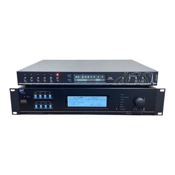
dCS 955
Stereo Digital to Analogue Converter
User Manual
Software Release 1.0x
June 2002
© 2001, 2002 dCS Ltd.
All rights reserved. Reproduction of this manual in any manner whatsoever,
1
without the written permission of dCS
is strictly forbidden. Additional copies of
this manual may be obtained from dCS.
Information contained in this manual is subject to change without notice, and
whilst it is checked for accuracy, no liabilities can be accepted for errors.
1
dCS is Data Conversion Systems Ltd. Company registered in England No. 2072115.
Advertisement
Table of Contents

Related Manuals for DCS 955


Summary of Contents for DCS 955
- Page 1 Information contained in this manual is subject to change without notice, and whilst it is checked for accuracy, no liabilities can be accepted for errors. dCS is Data Conversion Systems Ltd. Company registered in England No. 2072115.
- Page 2 955 User Manual Manual for Software Issue 1.0x dCS Ltd June 2002 Page 2 l filename: dCS955 Manual v1.0x.doc email: more@dcsltd.co.uk anua English version web-site: www.dcsltd.co.uk...
-
Page 3: Product Overview
June 2002 RODUCT VERVIEW The dCS 955 DAC (Digital to Analogue Converter) is a high performance converter intended for studio and live recording applications. It is designed to produce very high standard analogue output from high quality digital data formats (for example, 192kS/s or DSD) or standard formats (for example Red Book CD or 24/96). -
Page 4: Product Features
955 User Manual Manual for Software Issue 1.0x dCS Ltd June 2002 Product Features Formats • DSD, and PCM from 192kS/s down to 32kS/s • Data formats supported are: AES/EBU (XLR), Dual AES (XLR), Quad AES (XLR), AES data at TTL levels (BNC), SDIF-2 (PCM and DSD), SDIF-3 (DSD), DSD packed into 4 AES links and DSD packed into 3 AES links (P3D). -
Page 5: Table Of Contents
Other Settings Typical Applications..................18 Using a dCS 955 with SDIF DSD Using a Master Clock to Sync a dCS 955 Replaying Recorded DSD from an 8-track 16/44.1 PCM Recorder Operating Several Units on One Remote Chain Six Channel PCM Set Up Replaying Recorded 6 Channel DSD from a 24-Track 16/44.1 PCM Recorder 21... - Page 6 955 User Manual Manual for Software Issue 1.0x dCS Ltd June 2002 2.4 Phase 2.5 Dim Volume Setting 2.6 Function Shortcuts Menu 3. Display 3.1 Brightness Settings 3.2 Display Timeout 3.3 Lock Front Panel 3.4 Display Language Menu 4. Connector Settings 4.1 Sync Source...
- Page 7 Command Streams Example: Switching to 96k PCM Example: Switching to P3D General Technical Information...............86 Jitter and PLL bandwidths Using your dCS 955 for the first time..............88 What’s in the Box? Safety Notice Mains Voltage Setting Positioning the Unit Installing the Unit in a Rack Options ......................90...
- Page 8 Indexes and Software Version Numbers.............104 Software History Definitions and Abbreviations Key to Cable Identification List of Tables List of Figures Keywords and Phrases Selling your dCS 955 Privately Owner Registration Transfer Page 8 l filename: dCS955 Manual v1.0x.doc email: more@dcsltd.co.uk anua English version...
-
Page 9: About This Manual
June 2002 About this Manual If you have not used a dCS 955 before, please read the section “Using your dCS 955 for the first time” on page 88. This manual has been arranged with the most commonly used sections placed first: •... -
Page 10: Step-By-Step Guide
UIDE This section guides you through setting up the unit for basic operation. You may find this useful if you have not used the dCS 955 for a while. Preliminaries The Menu Guide sheet details the menu structure. For more information, see the Menu section, starting on page 26. -
Page 11: Step 1 - Setting The Input Format
955 User Manual Manual for Software Issue 1.0x dCS Ltd June 2002 Step 1 – Setting the Input Format MENU 1. DAC 1.1 Input Format Settings DSD (P3D mode) Figure 1 – Input Format Selection do this: Press Menu... -
Page 12: Step 2 - Selecting An Input
Connect the AES 1 (or AES A) output on your source equipment to the AES 1 input on the 955 rear panel and the AES 2 (or AES B) output to the AES 2 input, using two XLR cables. Ensure the cables are not swapped. -
Page 13: Connecting To A Pcm Quad Aes Or Dsd Quad Source
DSD-SDIF operation. do this: Connect the SDIF output on your source equipment to the DSD/SDIF connectors on the 955 rear panel using three coax cables. Connect CH1 out to CH1, CH2 out to and CLK out to CLK IN. -
Page 14: Step 3 - Connecting The Analogue Outputs
Use the Balanced Outputs if you want to connect 955 to a device with balanced inputs only. Connect to the destination with two screened XLR cables. IMPORTANT! The balanced outputs are semi-floating. Do not try to connect one side to an unbalanced input as this will prevent the output stage working properly. -
Page 15: Step 4 - Setting The Sync Source
Syncing to an External Wordclock If you want to synchronise your system to Wordclock from a Master Clock (such as a dCS 995 or dCS 992) or other stable source, do the following: do this: Set the Master Clock sample rate to match the source (probably 44.1 or 48kS/s). -
Page 16: Syncing To An Aes/Ebu Reference
June 2002 Syncing to an AES/EBU Reference If you want to synchronise your system to an AES/EBU Reference from a Master Clock (such as a dCS 995 or dCS 992) or other stable source, do the following: do this: Set the Master Clock sample rate to match the source (probably 44.1 or 48kS/s). - Page 17 955 User Manual Manual for Software Issue 1.0x dCS Ltd June 2002 Page 17 l filename: dCS955 Manual v1.0x.doc email: more@dcsltd.co.uk anua English version web-site: www.dcsltd.co.uk...
-
Page 18: Using A Dcs 955 With Sdif Dsd
Analogue Digital I/O Unbalanced Balanced - or - outputs outputs To pre or power amplifier Figure 4 – Syncing a 955 to a Master Clock do this: Set the menu to Sync Source Sync Mode Slave to Word Clock. do this: Set the menu to SDIF. -
Page 19: Replaying Recorded Dsd From An 8-Track 16/44.1 Pcm Recorder
Figure 6 – Multi-unit Remote Control daisy chain A PC running the Windows Remote Control program can control a mixture of dCS units (up to about 10) on each daisy chain. To make them individually addressable, each unit must be set to a different Address. -
Page 20: Six Channel Pcm Set Up
955 User Manual Manual for Software Issue 1.0x dCS Ltd June 2002 Six Channel PCM Set Up 24/96 Dual AES dCS 954 / 955 Channels 1 & 2 CH1(L) CH2(R) Sensitivity Reference In Reference Out AES1 AES2 AES3 AES4... -
Page 21: Replaying Recorded 6 Channel Dsd From A 24-Track 16/44.1 Pcm Recorder
955 User Manual Manual for Software Issue 1.0x dCS Ltd June 2002 Replaying Recorded 6 Channel DSD from a 24-Track 16/44.1 PCM Recorder dCS 954 / 955 CH1(L) CH2(R) Sensitivity Reference In Reference Out AES1 AES2 AES3 AES4 MAINS FUSE 2A(T) ON OFF... -
Page 22: Replaying 8 Channel P3D Dsd
Analogue out Figure 9 – 8 channel P3D DSD set up Four 955 units and a Master Clock can be used as above to convert 8 channels of P3D encoded DSD. Note that a 24-bit recorder is needed for P3D. -
Page 23: Upsampling A Cd
Set the Master Clock to generate 44.1 AND 96kS/s simultaneously. do this: If you do not have a Master Clock, you can slave the dCS 974 to the CD player by setting and slave the 955 to the dCS 974 by... -
Page 24: Converting Quad Aes To Single Aes
955 User Manual Manual for Software Issue 1.0x dCS Ltd June 2002 Converting Quad AES to Single AES Quad AES 192kS/s dCS 954 / 955 CH1(L) CH2(R) Sensitivity Reference In Reference Out AES1 AES2 AES3 AES4 MAINS FUSE 2A(T) ON OFF... -
Page 25: Replaying 24/192 From 2 Nagra-D Recorders
Quad AES 24/192 recordings split between 2 tapes may be played back as shown. The 2 Nagra-D recorders must be fitted with special hardware and software to achieve this – contact Nagra for details. The 955 allows for small timing discrepancies between the... -
Page 26: The Software - The Menu
955 User Manual Manual for Software Issue 1.0x dCS Ltd June 2002 – T OFTWARE Press the "Menu" button to open the menu, use the arrow buttons to move around the menu tree. MENU Press the "OK" button to select a menu or setting. Use the "Cancel" button to return to the previous menu level. -
Page 27: Using The Menu
955 User Manual Manual for Software Issue 1.0x dCS Ltd June 2002 Using the Menu The menu gives the user access to a wide range of additional features. It also allows new features and performance enhancements to be added at a later date by software upgrades. -
Page 28: Closing The Menu
955 User Manual Manual for Software Issue 1.0x dCS Ltd June 2002 ↓ ↓ ↓ ↓ do this: Use the button to move the highlight to and press the button. The display changes to: The channels are now swapped. -
Page 29: Top Level Menu
955 User Manual Manual for Software Issue 1.0x dCS Ltd June 2002 Top Level Menu The top level menu groups the menu features conveniently, reducing the menu navigation time. Sets some of the primary operating parameters of the DAC. - Page 30 955 User Manual Manual for Software Issue 1.0x dCS Ltd June 2002 Sets up the test tone generator and runs other test routines. Displays unit and contact information. Save and recall unit settings. Page 30 l filename: dCS955 Manual v1.0x.doc email: more@dcsltd.co.uk...
-
Page 31: Dac Settings Menu
955 User Manual Manual for Software Issue 1.0x dCS Ltd June 2002 Menu 1. DAC Settings 1. DAC Settings 1. DAC Settings 1. DAC Settings 1. DAC 1.2 Input 1.1 Input Format 1.3 Filter Settings 1.4 De-Emphasis 1.5 DDC Mode... -
Page 32: Filter Settings
955 User Manual Manual for Software Issue 1.0x dCS Ltd June 2002 1.3 Filter Settings 1.3 Filter Settings 1.3 Filter Settings 1.3 Filter Settings Selects an optional anti-image filter. For PCM mode, these offer different trade-offs between Nyquist imaging and energy smear. -
Page 33: Ddc Mode
955 User Manual Manual for Software Issue 1.0x dCS Ltd June 2002 1.5 DDC Mode 1.5 DDC Mode 1.5 DDC Mode 1.5 DDC Mode When set to On, performs sample rate and/or format conversion on the incoming data stream and outputs digital data. The conversion applied depends... -
Page 34: Unit Settings
955 User Manual Manual for Software Issue 1.0x dCS Ltd June 2002 Menu 2. Unit Settings 2. Unit Settings 2. Unit Settings 2. Unit Settings 2. Unit 2.1 Swap L / R 2.2 Automatic 2.3 Automatic 2.5 Dim Volume 2.6 Function... -
Page 35: Function Shortcuts
955 User Manual Manual for Software Issue 1.0x dCS Ltd June 2002 2.6 Function Shortcuts 2.6 Function Shortcuts 2.6 Function Shortcuts 2.6 Function Shortcuts Defines the function of the buttons. do this: Navigate to this menu and choose 1. The display will change to:... -
Page 36: Display Menu
955 User Manual Manual for Software Issue 1.0x dCS Ltd June 2002 Menu 3. Display 3. Display 3. Display 3. Display 3. Display 3.1 Brightness 3.2 Display 3.3 Lock Front 3.4 Display Menu Settings Timeout Panel Language 01 …. 15... -
Page 37: Connector Settings
955 User Manual Manual for Software Issue 1.0x dCS Ltd June 2002 Menu 4. Connector Settings 4. Connector Settings 4. Connector Settings 4. Connector Settings 4. Connector 4.5 Locking 4.6 RS232 4.1 Sync Source 4.2 AES Settings 4.3 BNC Settings 4.4 Messaging... -
Page 38: Aes Settings
955 User Manual Manual for Software Issue 1.0x dCS Ltd June 2002 4.2 AES Settings 4.2 AES Settings 4.2 AES Settings 4.2 AES Settings This menu sets the behaviour of the AES interfaces. It has one sub-menu: 4.2.1 Reference Mode 4.2.1 Reference Mode... -
Page 39: Simple View
0. IMPORTANT! When using the Windows Remote Control, each dCS unit in the daisy chain MUST be set to a different RS232 address. The RS-232 control formats and procedures are covered in more detail in the section “RS-232 Remote Control Interface”... -
Page 40: Metering Menu
955 User Manual Manual for Software Issue 1.0x dCS Ltd June 2002 Menu 5. Metering 5. Metering 5. Metering 5. Metering 5. Metering 5.2 Metering 5.3 Metering 5.4 Metering 5.1 Peak Hold Menu Type Speed Boost Always Hold Meter Both... -
Page 41: Metering Speed
955 User Manual Manual for Software Issue 1.0x dCS Ltd June 2002 Displays peak responding bargraph meters, left at Bars the top. The attack is instant, the decay is set by menu. The response is that Metering Speed of a peak program level meter. -
Page 42: Test Menu
955 User Manual Manual for Software Issue 1.0x dCS Ltd June 2002 Menu 6. Test 6. Test 6. Test 6. Test 6.3 Tone 6.6 Channel 6.7 Simulation 6. Test Menu 6.1 Test Tone 6.2 Tone Level 6.4 Test Display 6.5 Phase Check... -
Page 43: Phase Check
955 User Manual Manual for Software Issue 1.0x dCS Ltd June 2002 6.5 Phase Check 6.5 Phase Check 6.5 Phase Check 6.5 Phase Check Use this feature to check if one channel in your system is phase inverted. do this:... -
Page 44: Information Menu
Connect a CD player or transport to an AES input or the SDIF-2 input and select that input to lock the 955 to it. Ensure the unit is in PCM mode, not DSD. do this: Load up a dCS CD containing updated 955 software and ensure the player is NOT playing. -
Page 45: What Can Go Wrong With A Cd Download
“Error Not Locked To A 44.1 Source” and aborts the procedure. If the unit finds that the CD is not the right dCS CD, is some other CD or is unreadable, it will display “Invalid CD” and abort the procedure. -
Page 46: Store Menu
955 User Manual Manual for Software Issue 1.0x dCS Ltd June 2002 Menu Store Store Store Store 8.1 Recall 8. Store Menu 8.2 Save Settings Settings 8.1.1 User Stores: 1 …. 6 1 …. 6 8.1.2 Fixed Stores: A …. L Figure 22 –... - Page 47 Sync Mode - Audio Input, Auto Slave On, BNC to SDIF. do this: Connect up as shown on page 22. Slaving the DACs to a Master Clock such as a dCS 995 ensures accurate alignment with no special setups. – Multi-channel PCM Store D...
-
Page 48: Save Settings
955 User Manual Manual for Software Issue 1.0x dCS Ltd June 2002 – P3D DDC Store H Store H Store H Store H DSD P3D format, AES1-4, Filter 1, DDC Mode On. Connector Sync Mode - Audio Input, Auto Slave On, AES Ref Loop Terminated, BNC to SDIF. - Page 49 955 User Manual Manual for Software Issue 1.0x dCS Ltd June 2002 You can erase an existing store name: do this: Open the menu and scroll to the store name you want to Save Settings delete. Press , then press the...
-
Page 50: The Hardware - Controls And Connectors
On/Off button, then the button to set the unit to standby mode. The Analogue Outputs will mute, all displays will turn off. In this mode, the 955 uses very little power. do this: To restore normal operation, press the On/Off button briefly again. -
Page 51: Input Selection
955 User Manual Manual for Software Issue 1.0x dCS Ltd June 2002 Input Selection AES 4 buttons are used to select inputs and formats. The following sequence assumes that the menu setting is Input Format is Off. Automatic Input Selection... -
Page 52: Mute Button
Non-Audio flag Muting on a disk or tape. Main Display The main display tells you what the 955 is doing. • The Status display shows the lock status (Unlocked or sample rate), the selected filter, the selected input and the sync source. -
Page 53: Volume Up And Down ( ↑ / ↓ ) Buttons
955 User Manual Manual for Software Issue 1.0x dCS Ltd June 2002 (↑ ↑ ↑ ↑ ↓ ↓ ↓ ↓ Volume Up and Down ) Buttons When in PCM mode with the menu closed, these two buttons set the digital Volume control between 0.0dB and –120.0dB in 0.1dB steps. -
Page 54: Rear Panel
IEC power inlet Mains fuse holder Power switch Balanced Analogue Outputs If your pre or power amplifier has balanced inputs, connect the 955’s Balanced Analogue Outputs to them. For best results, connection of these outputs to unbalanced inputs is not recommended – use the... -
Page 55: Unbalanced Analogue Outputs
This usually involves connecting AES 1 (or AES A) on the source to AES 1 on the 955, AES 2 (or AES B) on the source to 2, and so on. Use with 110 ohm screened, twisted pair cable designed for digital audio or RF. -
Page 56: Clk In / Clk Out
The underside of the unit will have a label on that contains a number such as 955 4B1 6B2 2A1 3A2 12345. This is the serial number, but it also contains vital configuration information. We will need this number (all of it) to give you support over the phone, or to ship you software updates. - Page 57 955 User Manual Manual for Software Issue 1.0x dCS Ltd June 2002 Page 57 l filename: dCS955 Manual v1.0x.doc email: more@dcsltd.co.uk anua English version web-site: www.dcsltd.co.uk...
-
Page 58: Dcs 955 Technical Information
955 User Manual Manual for Software Issue 1.0x dCS Ltd June 2002 dCS 955 T ECHNICAL NFORMATION Converter Type • 5-bit, approximately 3MS/s oversampled, dCS patented Ring DAC topology. Digital Interface Specifications AES/EBU (AES3) Inputs Output Type Balanced, differential Impedance Ω... -
Page 59: Frequency Response (Set To Filter 1)
955 User Manual Manual for Software Issue 1.0x dCS Ltd June 2002 Frequency Response (set to Filter 1) • Fs=32kS/s +/-0.1dB, 10Hz to 15kHz • Fs=44.1 or 48kS/s +/-0.1dB, 10Hz to 20kHz • Fs=88.2 or 96kS/s +/-0.1dB, 10Hz to 35kHz •... -
Page 60: Analogue Output Specifications
The sample clock quality significantly determines the output performance of the converter. The highest quality clocks that are available are crystals, so we use these. The 955 uses two on-board voltage controlled crystal oscillators (VCXO’s) as clock sources - one for the 44.1kS/s related sample rates and one for the 48kS/s related sample rates. -
Page 61: Power Requirements
3.5” 18.7lbs Table 5 – Size and weight for professional products • All models are 1U high except dCS 972 and dCS 974 which are 2U. • Removable rack ears take the overall width to 483mm (19”). • Removable feet add an extra 8mm (0.32”) of height. -
Page 62: Operating Conditions
Allowing 3 cms (1.2”) between units gives reasonable cooling If in doubt, the easy test is – the 955 is happy to work anywhere a human is. dCS 9xx EXCESS TEMPERATURE (Measured as dCS 954 ) Middle unit of 3, in box with "shelf plates"... -
Page 63: Group Delay
DAC group delay was measured from SDIF-2 in to analogue out, and the ADC results inferred. The other dCS Pro ADCs and DACs use the same DSP code modules and the same digital engine, so these results apply. -
Page 64: Anti-Image Filtering
Filters 3 widely – so try them for yourself. The 955 uses linear phase FIR filters to avoid the limit cycle problems that come with many IIR filters. Linear phase gives filters a symmetrical transient response before and after a transient (“pre-ringing”). The passband may or may not have a ripple , depending on the filter being used. -
Page 65: Sample Alignment
June 2002 Sample Alignment The 955 aligns samples such that Word Clock Out aligns with AES3 samples , the rising edge of Word Clock Out aligning with the start of the first illegal code in the X,Z subframe preamble and the falling edge aligning with the start of the Y subframe preamble. -
Page 66: Figure 29 - Word Clock In To Word Clock Out, 96 Ks/S
955 User Manual Manual for Software Issue 1.0x dCS Ltd June 2002 When Word Clock In is used as a sync source, in and out are related as below. The lower waveform is the output, the upper one is the input. The misalignment is less than about 40ns. -
Page 67: Figure 31 - Aes3 In To Aes3 Out, 96Ks/S
AES3 input is used as a sync source. The alignment is better than 40ns. Input is at the top of the displays, output is at the bottom. Signals are at the sockets on the 955, the unit was slaved to AES input. Figure 31 – AES3 in to AES3 out, 96kS/s Figure 32 –... -
Page 68: Figure 33 - Word Clock In To Aes3 Out, 96Ks/S
955 User Manual Manual for Software Issue 1.0x dCS Ltd June 2002 AES3 out is also related to the phase of Word Clock In. The scope shots below were taken with the unit sync’d to Word Clock Figure 33 – Word Clock In to AES3 Out, 96kS/s Figure 34 –... -
Page 69: Aes3 (Aes/Ebu) Format
DCS1 Destination: null For more information on the way dCS implement the AES3 system message to handle higher sample rates, see the Appendix to this manual. For the formal definition of the AES3 interface, see footnote , from the AES. -
Page 70: How Far Will Aes3 Go
955 User Manual Manual for Software Issue 1.0x dCS Ltd June 2002 How Far will AES3 Go? The AES/EBU format was designed to go reasonable distances, at 44.1kS/s and 48kS/s. Figure 35 Figure 36 below show it over 16 m and 94 m (the source is the top trace) using average cables. -
Page 71: Figure 37 - Aes3 Format At 96Ks/S Over 16 Metres
955 User Manual Manual for Software Issue 1.0x dCS Ltd June 2002 At 96kS/s (twice the data rate the format was designed for) the allowed cable length is less. Figure 37 Figure 38 below show this over 16 m and 94 m. -
Page 72: Dsd Sdif-2
955 User Manual Manual for Software Issue 1.0x dCS Ltd June 2002 DSD (Direct Stream Digital) is a single bit very high sample rate (2.822MS/s) format, where the single bit words are heavily noise shaped to push noise energy above the audio band. The frequency response is very high (well above 100kHz) although at these high frequencies, much noise is also present. -
Page 73: Pcm Format
955 User Manual Manual for Software Issue 1.0x dCS Ltd June 2002 SDIF-2 PCM Format The SDIF-2 interface is a 4 wire NRZ interface - so the DC level on each signal line may not be constant. It contains 20 bits of audio data and has a block structure of 256 stereo samples, rather than the 192 of AES/EBU. -
Page 74: Sdif-2 Messaging
955 User Manual Manual for Software Issue 1.0x dCS Ltd June 2002 Figure 41 – SDIF-2 PCM format at 44.1 kS/s SDIF-2 Messaging The SDIF-2 message details are defined in the table following. DESCRIPTION Definition Undefined 0000 0xxx Emphasis... -
Page 75: Dsd On Sdif-2
Figure 43 – DSD using SDIF-2, timing DSD on SDIF-3 SDIF-3 embeds a clock in the SDIF-2 data stream. The 955 does not extract the embedded clock and so still requires a word clock to decode SDIF-3. SDIF-3 is used only for DSD – it is not used for PCM. Contact SONY for more details. -
Page 76: P3D Behaviour
Bit Error Rates The bit error rate (BER) for a dCS 904 / dCS 954 running P3D is below 5x10 , (0 errors over 64 hours). The same error rate is likely to hold for all AES3 type formats. -
Page 77: Remote Control Interface
All commands available from the front panel (and a few others, dCS use only) of a unit can be remotely controlled using this approach. Each unit must have a unique ID (in the range 0 to 99) which must be set up by hand using the menu system on the front panel. -
Page 78: Transmit Message
The addressed receiving unit (ADC, DAC, DDC, Master Clock, etc) acknowledges within 50ms of the last transmitted byte in the transmit message. For some special cases (dCS use only, see “Special Commands and Protocols” below) commands do not acknowledge. If the checksum is incorrect the receiving unit will ignore the command, clear its buffer and will not acknowledge. -
Page 79: Example
Address F1 hex (241 decimal), Command RS_ENABLE_DEBUG (19 decimal) ALL units on the daisy chain react to the command. Nothing acknowledges. This enables dCS debugging commands. This may result in unstable behaviour of the unit. Page 79 l filename: dCS955 Manual v1.0x.doc... -
Page 80: Command Streams
955 User Manual Manual for Software Issue 1.0x dCS Ltd June 2002 Command Streams Example – a system of 9 units with ID’s set up as noted: 1 Master Clock (ID 1), 4 P3D compatible ADCs (ID 2, 3, 4 and 5), 4 P3D compatible DACs (ID 6, 7, 8 and 9). - Page 81 955 User Manual Manual for Software Issue 1.0x dCS Ltd June 2002 Responds -> [ACK 15 seconds][7], requested mode Transmit -> [8][DSD_MODE], to change mode to PCM of unit 8 Responds -> [ACK 15 seconds][8], requested mode Transmit -> [9][DSD_MODE], to change mode to PCM of unit 9 Responds ->...
-
Page 82: Example: Switching To P3D
955 User Manual Manual for Software Issue 1.0x dCS Ltd June 2002 The system is now set up with the Master Clock configured for 96k operation and the ADCs and DACs locked in PCM mode to 96k. Example: Switching to P3D Change the Master Clock frequency to 44.1k prior to changing the ADC and... - Page 83 955 User Manual Manual for Software Issue 1.0x dCS Ltd June 2002 5) Check ADCs for mode change. This command allows the Transmitter to check the mode of the ADCs. If a unit has not changed the transmitter should go back to step 9 and repeat the command.
- Page 84 955 User Manual Manual for Software Issue 1.0x dCS Ltd June 2002 Command name Parameters RS_AUTO_SLAVE 0 = do not automatically slave 1 = automatically slave to a reference input RS_MASTERSLAVE First parameter 1 = Master 0 = Slave.
-
Page 85: Table 9 - Rs-232 Command Set
955 User Manual Manual for Software Issue 1.0x dCS Ltd June 2002 Command name Parameters RS_ACUT 1 = Disable Auto Digital Muting RS_FINE_LOCK_MODE 1 = Use coarse lock 0 = use fine lock RS_WAVETYPE 0 = Signal Generator Off... -
Page 86: General Technical Information
1 Hz, they get worse. Because of these types of issue, dCS use a bandwidth of around 5 Hz for our PLLs in fine lock. This bandwidth enables jitter in the audio band to be substantially suppressed, but lock in times do not become excessive. - Page 87 955 User Manual Manual for Software Issue 1.0x dCS Ltd June 2002 Using this approach, rather than any approach based on FIFOs, ensures that delay between data coming in and replaying is minimised. If a FIFO approach is used, the FIFO has to be significantly filled at all times, which is the same as a delay in the signal path.
-
Page 88: Using Your Dcs 955 For The First Time
Replacement packaging can be ordered from dCS or our distributors. Your re-seller should arrange for you to receive a dCS Extended Warranty Certificate within 30 days of purchasing a new dCS 955. If it does not arrive, please contact dCS. Please keep the Extended Warranty Certificate in a safe place. -
Page 89: Installing The Unit In A Rack
955 User Manual Manual for Software Issue 1.0x dCS Ltd June 2002 Installing the Unit in a Rack The unit is supplied with 19” rack mount ears fitted. If it is rack mounted, use the ears to locate the unit in the rack and stop it sliding forward – but: IMPORTANT! The ears are not strong enough to be used as the only mechanical support. -
Page 90: Options
44.056kS/s and 47.952kS/s). This option must be fitted at dCS to allow full checking. Contact dCS for details. Rack Slide All 955 units will accept a pair of telescopic rack slide rails to facilitate 19” rack mounting. Mains Supply Voltage Any unit may be set for operation from 230/240V, 215/220V, 200V, 115/120V or 100V A.C. - Page 91 955 User Manual Manual for Software Issue 1.0x dCS Ltd June 2002 Page 91 l filename: dCS955 Manual v1.0x.doc email: more@dcsltd.co.uk anua English version web-site: www.dcsltd.co.uk...
-
Page 92: Maintenance And Support
All parts are replaceable or upgradeable by dCS, for a period of at least five years from the date of original purchase of your unit. If your unit is damaged in some way, please contact your re-seller or dCS. -
Page 93: Warranty
Owner Registration form at the time of sale and returning it to dCS. If you have bought a new dCS 955 and do not receive an Extended Warranty Certificate for this unit within 30 days of purchase, please note the serial number on the underside of the unit and contact dCS. -
Page 94: Updating Your Dcs 955
If the software loaded in your unit is (for example) version 3.45: • A change to version 3.46 indicates a minor update for internal dCS use – to make testing easier, or more thorough, or to cater for some minor hardware change. -
Page 95: During An Update
You may wish to have your hardware updated from time to time to take advantage of new features in the latest software. dCS offer this service - we will retest, reset any adjustable items to current shipping standards, and install any modifications or updates that have occurred since your unit was first shipped. -
Page 96: Safety And Electrical Safety
Ltd June 2002 Safety and Electrical Safety There are no user serviceable parts inside the 955 and so there is no need to remove the covers. If for some reason you do: IMPORTANT! Disconnect the power cable before removing any covers or changing the fuse. - Page 97 955 User Manual Manual for Software Issue 1.0x dCS Ltd June 2002 Page 97 l filename: dCS955 Manual v1.0x.doc email: more@dcsltd.co.uk anua English version web-site: www.dcsltd.co.uk...
-
Page 98: Troubleshooting
Check that the source is switched on. • Some types of source equipment do not generate a digital output when idling - set the source to “play” mode and check that the 955 locks. • Try setting the menu to... -
Page 99: The Unit Fails To Respond To The Controls
955 User Manual Manual for Software Issue 1.0x dCS Ltd June 2002 The unit fails to respond to the controls • While locking to a source or changing some settings (e.g. Filter), the microcontroller inside the unit is busy and will not respond to new commands for a few seconds. -
Page 100: One Output Channel Is Low Or Absent
Master Clock. If the unit is being driven by an upsampler or DDC, you will probably need a Master Clock that can output different sample rates, such as the dCS 995 or 992. Otherwise, slave the 955 to the upsampler / DDC outputs. -
Page 101: The Sound Has A Peculiar Tonal Balance
955 User Manual Manual for Software Issue 1.0x dCS Ltd June 2002 The sound has a peculiar tonal balance • If the source is AES and the sample rate is 48kS/s or lower, the De- Emphasis setting may be incorrect. Set the menu to Auto. -
Page 102: If You Need More Help
In the first instance, you should contact your dealer / re-seller or distributor. If he cannot resolve the issue, contact dCS. Our office hours are 8:30 a.m. to 5:00 p.m. Monday to Friday, UK time (UTC or UTC + 1hr). Contact us by phone or... - Page 103 955 User Manual Manual for Software Issue 1.0x dCS Ltd June 2002 Page 103 l filename: dCS955 Manual v1.0x.doc email: more@dcsltd.co.uk anua English version web-site: www.dcsltd.co.uk...
-
Page 104: Indexes And Software Version Numbers
OFTWARE ERSION UMBERS Software History This manual is for dCS 955 software version 1.0x. Definitions and Abbreviations A relative signal level or ratio in decibels. The context may indicate the reference level. A signal level relative to 0.775V rms, making no allowance for external loading. -
Page 105: Key To Cable Identification
Table 4 – Power consumption for professional products ........61 Table 5 – Size and weight for professional products......... 61 Table 6 – dCS 904 ADC group delay in µs, v1.31 software ....... 63 Table 7 – dCS 954 DAC group delay in µs, v1.30 software ....... 63 Table 8 –... -
Page 106: List Of Figures
Figure 2 – Sync Source Selection ..............15 Figure 3 – SDIF-DSD input configuration............18 Figure 4 – Syncing a 955 to a Master Clock ............18 Figure 5 – Replaying recorded 2 channel DSD from an 8-track 16/44.1 PCM recorder ................... -
Page 107: Keywords And Phrases
98 baud rates, RS-232 interface......77 dB..............104 BER ............76, 87 dBu.............. 104 bit error rate ..........76, 87 dCS contact details menu ......44 BNC PCM format menu.........38 DDC ............104 BNC settings menu........38 DDC mode ............ 48 brightness menu ..........36 DDC mode menu .......... - Page 108 955 User Manual Manual for Software Issue 1.0x dCS Ltd June 2002 display language menu........36 frequency response ........ 59, 72 display menu..........36 front panel ............. 50 display timeout menu........36 front panel controls are locked...... 36 display, main..........52 full scale ............104 display, Meter ..........52...
- Page 109 955 User Manual Manual for Software Issue 1.0x dCS Ltd June 2002 Menu Operation buttons ......27, 52 menu, unit settings........34 menu time out..........28 menu, unit temperature......... 44 Menu Up / Down buttons .......27 menu, using ..........27 menu, AES settings ........38 message, AES3 ..........
- Page 110 955 User Manual Manual for Software Issue 1.0x dCS Ltd June 2002 oversampling ..........58 renaming a store ........... 48 overview............3 reset to factory setup ........46 owner registration transfer.....93, 113 Ring DAC ............58 RS-232 ............56 RS-232 address ..........77 RS232 address menu ........
- Page 111 Wordclock .........15 updates, software.......... 94 updating manuals.......... 95 updating software from PC ......94 technical notes..........102 updating your 955 ......... 94 temperature, ambient ........62 upsampling............ 23 temperature, internal .......44, 62 using for the first time........88 temperature, operating ........62 using the menu ..........
-
Page 112: Selling Your Dcs 955 Privately
June 2002 Selling your dCS 955 Privately If you dispose of your 955 by a private sale within the warranty period, you will enhance its value if you transfer the balance of the Extended Warranty to the new owner. Please fill in the Owner Registration Transfer document on the next page, sign it and return it to dCS, together with your Extended Warranty Certificate within 30 days of the sale. -
Page 113: Owner Registration Transfer
To transfer the balance of the Extended Warranty to a new owner, please complete the form below in block capitals and forward it, with the Extended Warranty Certificate, to dCS at the address below within 30 days of the sale. dCS Ltd...
Need help?
Do you have a question about the 955 and is the answer not in the manual?
Questions and answers