Table of Contents
Advertisement
Quick Links
Advertisement
Table of Contents

Related Manuals for ITT Industries FLYGT B2060


Summary of Contents for ITT Industries FLYGT B2060
- Page 1 2060/3060 INSTALLATION, CARE AND MAINTENANCE 890169/09...
-
Page 2: Table Of Contents
GUARANTEE Flygt undertakes to remedy faults in products sold by Hence, the guarantee does not cover faults caused Flygt provided: by deficient maintenance, improper installation, in- correctly executed repair work or normal wear and — that the fault is due to defects in design, materials tear. -
Page 3: Product Description
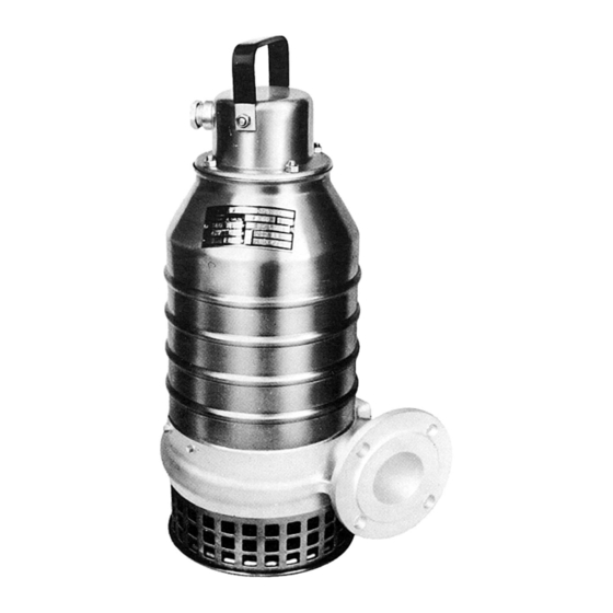
PRODUCT DESCRIPTION Applications Design B2060 and C3060 are designed for drainage respec- B2060 and C3060 are submersible electric motor- tively pumping of industrial waste water, when high driven centrifugal pumps. demands regarding corrosion resistance are required. Impellers Liquid temperature: The pump is available with the following types of C2060 –... -
Page 4: Technical Data
Technical data Monitoring equipment The stator incorporates two thermal switches B 2060 connected in series. The pump curves show: The thermal switches open at 125°C (260°F) and — input power at various operating points. close at 70°C (160°F). — flow rate versus total head. The monitoring equipment shall be of a design that makes automatic restart impossible. -
Page 5: Transportation And Storage
TRANSPORTATION AND STORAGE The pump may be transported and stored in a vertical before it is started. Never use an open flame to thaw or horizontal position. Make sure that it is securely the pump. fastened and cannot roll or fall over. For longer periods of storage, the pump must be Always lift the pump by its carrying handle or lifting protected against moisture and heat. - Page 6 CP installation CS version All dimensions are in mm (in). In the CS version, the pump is transportable and intended to operate completely or partially submerged Provide a barrier around the pump pit, for example a in the pumped liquid. guard rail.
- Page 7 B2060 CT version In the CT version, the pump is installed in a stationary Pump installation position in a dry well next to the wet sump. Run the cables so that they do not have any sharp The pump has a watertight motor and will therefore bends and are not pinched.
-
Page 8: Electrical Connections
ELECTRICAL CONNECTIONS 6-lead stator WARNING! All electrical equipment must be earthed. This applies to both pump equipment and any monitoring equipment. Failure to heed this warning may cause a lethal accident. Make sure that the earth lead is correctly connected by testing it. Check that the main (line) voltage and frequency agree with the specifications on the pump data plate. - Page 9 9-lead stator * NOTE! When connecting pumps which have 1 9-lead stator for 460V Y Ser. 60 Hz, no closing links should be used. For correct connection, see inside of junction box cover.
- Page 10 Connect the control leads to the terminal board. 4-lead stator Make sure that the pump is correctly earthed (only 60 Hz, 1 phase) (grounded). Install the cover (51). Remember that the starting surge with the direct-on line start can be up to six times higher than the rated current.
-
Page 11: Before Starting
Before starting Starting jerk Check the oil level in the oil casing. Check that the monitoring equipment (if any) works. Check the direction of rotation. See the figure. The impeller shall rotate clockwise, as viewed from above. When started, the pump will jerk in the opposite direction to the direction in which the impeller rotates. -
Page 12: Care And Maintenance
CARE AND MAINTENANCE Safety precautions Inspection Regular inspection and preventive maintenance WARNING! ensure more reliable operation. Before starting work on the The pump should be inspected at least every 1000 pump, make sure that the pump hours, more frequently under severe operating condi- is isolated from the power tions. - Page 13 Recommended inspections: Inspection of Action Visible parts on pump Replace or fix worn and damaged parts. and installation Make sure that all screws, bolts and nuts are tight. Check the condition of carrying handle/lifting eyes, chains and wire ropes. Check that the guide bars are vertical. Pump casing and Replace worn parts if they impair function.
- Page 14 Inspection of Action Cable entry Make sure that the cable clamps are tight. If the cable entry leaks: — check that the entry is tightened so it bottoms out. — cut a piece of the cable off so that the seal sleeve (40) closes around a new position on the cable.
-
Page 15: Changing The Oil
Changing the oil WARNING. If the seal leaks, the oil casing may be In applications where poisonous properties are of less under pressure. Hold a rag over the oil plug to prevent concern, a mineral oil with viscosity up to ISO VG32 splatter. -
Page 16: Replacing The Suction Cover (C 3060)
Installing and adjusting the impeller Installing and adjusting the impeller Make sure that the end of the shaft is clean and free Make sure that the end of the shaft is clean and free of burrs. Polish off any flaws. of burrs. -
Page 17: Accessories And Tools
ACCESSORIES AND TOOLS Tools Start and control equipment The following tools are required in order to perform the Flygt has suitable start and control equipment for the necessary care and maintenance of the pump: pump. Contact Flygt for further information. Order No. -
Page 18: Fault Tracing (Troubleshooting)
FAULT TRACING (Troubleshooting) A universal instrument (VOM), a test lamp (continuity Use the following checklist as an aid to fault tracing. tester) and a wiring diagram are required in order to It is assumed that the pump and installation have carry out fault tracing on the electrical equipment. - Page 19 2. Pump starts but motor protection trips Is the motor protection Adjust. set too low? (Check with data plate) Is the impeller difficult to Clean the impeller. rotate by hand? Clean out the sump. Check that the impeller is not adjusted too tight. If anything else is wrong, contact Flygt service shop.
- Page 20 3. The pump does not stop Is the pump able to empty Check: the station to the stop level? — for leakage in pipe and/or discharge connection. — that the impeller is not clogged. WARNING: disconnect power before checking the impeller. —...
- Page 21 5. Pump runs but delivers too little or no water Check: — direction of rotation of the pump, see “Before starting”. — the valves are open and intact. — that pipes, impeller and strainer are not clogged. — that the impeller rotates easily. —...
-
Page 22: Service Log
SERVICE LOG Most recent Pump No. Hours of Remarks Sign. service date operation... - Page 23 SERVICE LOG Most recent Pump No. Hours of Remarks Sign. service date operation...
- Page 24 C 3060 C 3060 with stool for dry installation with automatic discharge connection assembly...
- Page 25 B 2060...
- Page 26 C 3060...
- Page 28 2060/3060.01.09. Eng. 0.5M. 10.97 © ITT FLYGT AB 890169...
Need help?
Do you have a question about the FLYGT B2060 and is the answer not in the manual?
Questions and answers