Table of Contents
Advertisement
Quick Links
Advertisement
Table of Contents

Related Manuals for ITT Industries FLYGHT 3153


Summary of Contents for ITT Industries FLYGHT 3153
- Page 1 Installation, Care and Maintenance 3153 893544/06...
-
Page 2: Table Of Contents
3153 CONTENTS Safety ____________________________ Electrical connections ________________ 10 Connection of stator and motor leads _________ 11 Data plate interpretation _______________ 3 Sensor connections _______________________ 16 Guarantee _________________________ Operation ______________________________ 18 Product description ____________________ 4 Before starting ____________________________ 18 Introduction _______________________________ 4 Care and Maintenance _________________ 19 Application ________________________________ 4... -
Page 3: Data Plate Interpretation
3153 DATA PLATE INTERPRETATION General data plate Serial number Product code + Number Curve code / Propeller code Country of origin Product number Additional information Phase; Type of current; Frequency Rated voltage Thermal protection Thermal class Rated shaft power International standard Degree of protection Rated current Rated speed... -
Page 4: Guarantee
3153 GUARANTEE Flygt undertakes to remedy faults in products sold by — that all service and repair work is done by a work Flygt provided: shop authorized by Flygt; — that genuine Flygt parts are used. — that the fault is due to defects in design, materials or workmanship;... -
Page 5: Motordata
3153 Motordata 60 Hz, 12 hp, (8.9 kW) 1760 r/min, 50 Hz, 7.5 kW, 1460 r/min, 3~, 4-pole 3~, 4-pole Voltage Rated Starting current A current A Voltage Rated Starting current A current A 230VD 380VD 230Y// 380VY 460VD 400VD 575VD 400VY 600VD... -
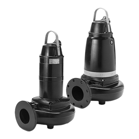
Page 6: Design Of The Pump
3153 DESIGN OF THE PUMP Motor Monitoring equipment Squirrel-cage 3-phase induction motor for 50 Hz or The stator incorporates three thermal contacts conn- 60 Hz. ected in series that activate an alarm at overtempe- The motor is started by means of direct on-line or rature. - Page 7 3153 With cooling jacket Shaft The shaft is delivered with the rotor as an integral part. Shaft material; stainless steel. Inspection chamber Cooling (with cooling jacket) The inspection chamber is The motor is cooled by a closed equipped with a FLS10 loop cooling system.
-
Page 8: Transportation And Storage
3153 TRANSPORTATION AND STORAGE The pump may be transported and stored in a vertical flame to thaw the pump. The pump shall be run for a or horizontal position. Make sure that the pump cannot short period after being taken up in order to expel all roll or fall over. -
Page 9: Safety Precautions
3153 Safety precautions Level regulators or other control equipment for start, stop and alarm. In order to minimize the risk of accidents in connec- Cable holder for holding the cable and regulating the tion with service and installation work, the following height of the level regulators. -
Page 10: Electrical Connections
3153 The pump has a watertight motor and will therefore not S- installation be damaged in the event of flooding. The pump is equipped with a cooling jacket. In addition to the pump the following items are required: Support stand for anchoring the pump to a base. Shut-off valves to permit the pump to be removed for In the S- installation, the pump is transportable and service. -
Page 11: Connection Of Stator And Motor Leads
3153 NOTE for Ex version Bear in mind the risk of electrical chock and the risk of explosion if — Electrical connections on the ex- the electrical connections are not plosion-proof motor must be made correctly carried out. by authorized personnel. Flygt disclaims all responsibility When using a variable-frequency-drive (VFD) the for work done by untrained, unau-... - Page 12 3153 SUBCAB 4G/SUBCAB AWG* “Electrical panel/starter” “Electrical panel/starter” 1 2 3 4 5 6 7 L1 L2 L3 1 2 3 4 5 6 7 L1 L2 L3 Subcab Subcab Subcab Subcab 7x1,5 4G x 7x1,5 4G x x AWG/4 x AWG/4 x AWG/7 x AWG/7...
- Page 13 3153 SUBCAB 7G SUBCAB Pump terminal Mains Lead board Stator lead Pump terminal board 1 black U1, red 2 black W2, black 3 black V1, brown 4 black U2, green 5 black W1, yellow 6 black V2, blue Earth (Ground) Yellow/Green Control Cable lead...
- Page 14 3153 SUBCAB 7G “Electrical panel/starter” 1 2 3 4 5 6 7 L1 L2 L3 L1 L2 L3 Subcab Subcab 7x1,5 7G x 1 2 3 4 5 6 7 T2 T1 1 See sensor connections To sensors SUBCAB Pump terminal Stator lead Pump terminal board Mains...
- Page 15 3153 SUBCAB 4G/SUBCAB AWG* “Electrical panel/starter” “Electrical panel/starter” 460V-Y SER 230V-Y// 1 2 3 4 5 6 7 1 2 3 4 5 6 7 L1 L2 L3 L1 L2 L3 Subcab Subcab Subcab Subcab 4G x 7x1,5 7x1,5 4G x x AWG/4 x AWG/4 x AWG/7...
-
Page 16: Sensor Connections
3153 Sensor connections For a PTC-thermistor (PTC = Positive Temperature Coefficient), there is a significant increase in resistance Monitoring equipment at a certain temperature that can be utilized for monitoring the temperature. The FLS10 sensor is installed in the inspection chamber and consists of a small float switch. - Page 17 3153 FLS10 + thermal contacts mA = Overtemperature mA = OK mA = Leakage Tolerance 10% POWER SUPPLY 24 V AC/DC MiniCAS II RESET THERMAL Circuits shown CONTACTS de-energised SENSOR 12 VDC INPUT FLS10 PUMP TERMINALS LEAKAGE ALARM LEAKAGE HIGH STATOR TEMP. HIGH TEMP AUX.
-
Page 18: Operation
3153 OPERATION Before starting Check that the visible parts of the pump and installation are undamaged and in good condition. Re- move the fuses or open the circuit breaker and check that the impeller can be rotated freely. Check that the monitoring equipment works. Check the direction of rotation. -
Page 19: Care And Maintenance
3153 CARE AND MAINTENANCE Service/Inspection The time between Major Service could vary con- ITT Flygt recommends a preventive maintenance pro- gram based on Intermediate and Major Services at siderably depending on operating conditions and the need for a Major Service will be determined during the regular intervals. - Page 20 3153 Before starting work on the pump, If any indication of Actions make sure that the pump is isolated alarm between in- from the power supply and cannot spections, please be energized. see instructions This applies to the control circuit below.
-
Page 21: Changing The Coolant
3153 Changing the coolant Emptying coolant Emptying coolant (without cooling jacket) (with cooling jacket) Filling plugs in/out Filling plugs in/out 44 Nm (33 ft lb) 44 Nm (33 ft lb) 30730 30692 Relief table Flygt part no. 395 77 00 1. -
Page 22: Removing The Impeller
3153 Removing the impeller 30590 Place the pump horizontally. Remove the flush Using a 12 mm hexagon bit adaptor (allen socket) with valve cover and it’s o-ring. Insert a rod (wood or a 100 mm (4″) extension (minimum length) turn the plastic) through the hole and lock the impeller in gland screw counter clockwise until the impeller breaks place. -
Page 23: Installing The Impeller
3153 Installing the impeller Before assembling, check that the impeller screw is clean and easy to screw into the shaft end (a). This to Make sure that the end of the shaft is clean and free from burrs. Polish off any flaws with fine emery cloth. prevent the shaft to rotate with the impeller screw. -
Page 24: Fault Tracing
3153 FAULT TRACING (TROUBLESHOOTING) A universal instrument multimeter (VOM), a test lamp when the power supply is turned on. (continuity tester) and wiring diagram are required in Use the following checklist as an aid to fault tracing. It order to carry out fault tracing on the electrical equip- is assumed that the pump and installation have for- ment. - Page 25 3153 2. Pump starts but motor protection trips Is the motor protection set Adjust. too low? (Check with data plate) Is the impeller difficult to Clean the impeller. rotate by hand? Clean out the sump. WARNING: disconnect power Check that the impeller is properly trimmed. before checking the impeller If anything else is wrong, contact Flygt service shop.
- Page 26 3153 3. The pump does not stop (when level control is used) Is the pump able to empty the Check: station to the stop level? — for leakage in pipe and/or discharge connection. — that the impeller is not clogged. WARNING: disconnect power before checking the impeller.
-
Page 27: Service Log
3153 5. Pump runs but delivers too little or no water Check: — direction of rotation of pump, see "Before starting". — that valves are open and intact. — that pipes and impeller are not clogged. — that the impeller rotates freely. —... - Page 28 www.flygt.com...
Need help?
Do you have a question about the FLYGHT 3153 and is the answer not in the manual?
Questions and answers