Table of Contents
Advertisement
Quick Links
Operating instructions
Translation of the original German version
Version 1.10 en, 20.01.2022
D
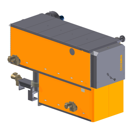
Underfeed grate UTSP
Series, Type:
Fabrication number:
System name:
Year of manufacture:
UTSP-
See nameplate
2022
Schmid AG
energy solutions
Hörnlistrasse 12
8360 Eschlikon
Switzerland
www.schmid-energy.ch
Advertisement
Table of Contents

Related Manuals for Schmid UTSP-180


Summary of Contents for Schmid UTSP-180
- Page 1 Operating instructions Translation of the original German version Version 1.10 en, 20.01.2022 Underfeed grate UTSP Series, Type: UTSP- Fabrication number: See nameplate System name: Year of manufacture: 2022 Schmid AG energy solutions Hörnlistrasse 12 8360 Eschlikon Switzerland www.schmid-energy.ch...
-
Page 2: Table Of Contents
Table of Contents Safety instructions ..........D-5 Intended use . - Page 3 Nomenclature key ..........D-30 Inlet design variants .
- Page 4 Maintenance ...........D-50 Introduction .
-
Page 5: Safety Instructions
This is clearly stated in the order confirmation of Schmid AG energy solutions and in the project design. Any other use, or the use of any other fuels is considered contrary to the intended use. The manufacturer is not liable for any damage resulting from such use. -
Page 6: Combustion Grate And Boiler
1 Safety instructions 1.1.2 Combustion grate and boiler The values specified on the nameplate must be adhered to. Failure to adhere to these specifications voids the warranty on system parts, mechanics and guaranteed emissions. This applies to the following values in particular: •... -
Page 7: Residual Risks
1 Safety instructions Residual risks The machine is built to the state of the art and in conformity with recognized safety stan- dards. The following residual risks exist and should be kept in mind when operating the machinery. Residual risks associated with specific phases of the service life of the system are detailed in the corresponding chapters of these instructions. -
Page 8: Danger When Entering The Combustion Chamber
1 Safety instructions DANGER! Risk of explosion (deflagration)! Risk of flame exposure when opening the combustion chamber door! In the event of faulty pre-ventilation or incomplete combustion, an explosive atmo- sphere can occur in the combustion chamber due to the formation of carbon monoxide (CO). -
Page 9: Warning Signs
1 Safety instructions WARNING! Risk of injury due to rotating parts. Before entering the combustion chamber, switch off the grate de-ashing screw on the maintenance switch and secure with the personal padlock to prevent reactivation. Warning signs Sign below the main switch of the electri- RISK OF FATAL ELECTRIC SHOCK cal circuit cabinet 5 compulsory safety rules for working... - Page 10 1 Safety instructions DANGER OF EXPLOSION/ DEFLAGRATION! Do not open the furnace door during start-up and ignition! HOT SURFACES! Always wear full protection gear (gloves, goggles, long-sleeved cotton garments). Sign next to combustion chamber door FIRE HAZARD/ • Do not open during start-lighting pro- RADIANT HEAT! Only open the furnace door briefly cedure...
-
Page 11: Emergency Shut Down
1 Safety instructions Emergency shut down The movement of the wood combustion system can be stopped at any time by activating the emergency stop button. Opening the combustion chamber door or the boiler door stops the movement of the system. Exception: the flue gas fan continues to run. Removal of the ash container stops the movement of all of the ash removal components. -
Page 12: Combustion Air Supply To The Heating Room
1 Safety instructions 1.7.1 Combustion air supply to the heating room Depending on the desired capacity, a certain air flow rate is necessary for wood combus- tion (combustion air). The size of the openings is determined during planning in accordance with the valid local directives (e.g. -
Page 13: Safety And Monitoring Systems
1 Safety instructions Safety and monitoring systems The detailed description of the error messages is given in Register "C User manual, Control unit", section "11 Events". 1.8.1 Overview (In compliance with EN 303-5:2012) Fig. 1 Safety and monitoring systems Item Description Function Back fire thermostat... -
Page 14: Thermal Extinguishing Water Valve (Optional
A drinking water separator must be installed in the extinguishing water supply in compliance with specific national regulations. An annual functional check must be carried out on the thermal extinguishing water valve. This inspection work may only be carried out by service personnel of Schmid AG energy solutions. Underfeed grate UTSP D-14 1.10 en... -
Page 15: O2 Sensor (Lambda Sensor
The customer can provide emergency stop buttons on the access doors and escape routes to the heating room that can be integrated into the control cabinet front. Actu- ating the emergency stop button stops the system controlled by Schmid AG energy solu- tions. -
Page 16: Operator Workstations
1 Safety instructions Operator workstations Access to the system must be possible on all sides for the following tasks: • General operation • Fire monitoring • Flue gas duct cleaning and flue gas recovery • Cleaning of the combustion chamber •... -
Page 17: Description Utsp
2 Description UTSP Description UTSP Introduction This automatic underfeed combustion system is designed for the economical and low- emission combustion of pellets. The energy released by combustion is used thermally. Depending on the heat requirements, the combustion system adjusts its capacity within a range of 30 to 100 percent. -
Page 18: Heat Storage
25 litres per kW of the nominal heat capacity. Schmid AG generally recommends installing a minimum heat storage volume of 30 litres per kW of the nominal heat capacity of the largest boiler, regardless of the boiler size. -
Page 19: Description Of Functions
2 Description UTSP Description of functions To ensure optimal combustion, the fuel, which is dosed with the stoker screw, undergoes the necessary phases: • Drying • Gasification (pyrolysis) • Combustion (oxidation) • Charcoal burnout In order to control this process, the system has two different air supply zones. •... - Page 20 2 Description UTSP The following measurements control the combustion process: • Primary air quantity • Secondary air quantity • Combustion temperature • Excess air measurement (Lambda) • Underpressure in the combustion chamber The combustion grate is filled with refractory concrete. •...
- Page 21 2 Description UTSP Fine particle filter A fine particulate filter can be optionally integrated into the system. Additional informa- tion is given in the separate instruction manual. The flue gas is further purified through a fine particle filter. If the filter is operated with underpressure, it is installed upstream of the flue gas fan.
-
Page 22: Structure Of The Wood Combustion System
2 Description UTSP Structure of the wood combustion system The automatic wood combustion system consists of the following system components: 13,15 10,11 Fig. 5 Structure of the wood chip combustion system Underfeed grate UTSP D-22 1.10 en... - Page 23 2 Description UTSP Item Designation Description / Comments Fuel transport, inlet Inlet for fuel, e.g. via stoker screw Combustion grate Consists of a vault, refractory lining, and a combustion retort Hot water boiler Heats the hot water Boiler door Access to the hot water boiler Flue gas dedusting (cyclone separator) Usually by means of a multi-cyclone Location of the flue gas fan The flue gas fan may also be located...
-
Page 24: Automatic Boiler Tube Cleaning (Optional
2 Description UTSP 2.4.1 Automatic boiler tube cleaning (optional) The thermally insulated boiler door swings out fully to enable proper cleaning of all boiler pass- es. A powerful blast of pressurised air cleans the inside of the boiler tubes. The air rapidly cleans loose ash particles sticking to the inside of the tubes. -
Page 25: Temperature Safety Valve
2 Description UTSP 2.4.3 Temperature safety valve The thermal process safeguard is designed for discharging the boiler idle capacity, e.g. in the event of failure of the boiler pump or a power failure. In the event of excess temperatures the thermostatic valve opens automatically and cools the boiler. Discharge must be effected through a heat-resistant pipe. - Page 26 A drinking water separator must be installed in the extinguishing water supply in compliance with specific national regulations. An annual functional check must be carried out on the thermal process safeguard. This inspection work may only be carried out by service personnel of Schmid AG energy solutions. Operating range (kW)
-
Page 27: Flue Gas Recovery (Option
Flue gas recovery Item Designation Recirculation fan Check flap valve Swing-type check valve Temperature monitoring Cleaning openings Boiler size Flue gas recovery (mm) UTSP-180-240 120 / 100 UTSP-300-360 120 / 100 UTSP-450-550 150 / 150 UTSP-700-900 150 / 150 Underfeed grate UTSP 1.10 en... -
Page 28: Active Postcombustion Grate
2 Description UTSP 2.4.5 Active postcombustion grate The burnout zone comprises rows of air-cooled grate elements. Each second grate row is moved by a joint drive motor with an eccentric drive. The air flow is adjusted with a manual flap below the primary air supply. -
Page 29: Flue Gas Filter System (Option
2 Description UTSP Before carrying out any maintenance work on the automatic boiler tube cleaning system, the compressed air tank of the cleaning system must be disconnected from the air supply (e.g. by closing the ball tap or releasing the quick-action coupling on the compressor). -
Page 30: Nomenclature Key
2 Description UTSP Nomenclature key Using as an example the UTSP-700.22 underfeed combustion system -700 UTS = combustion P = underfeed com- Output capaci- Type of de-ashing system system bustion system ty in kW 21 Combustion system with ash tray 22 De-ashing in container or bucket Inlet design variants... -
Page 31: Technical Data
2 Description UTSP Technical data 2.8.1 Dimensions Fig. 12 Dimensions with- with- Capacity (kW) (mm) (mm) (mm) (mm) (mm) (mm) (mm) (mm) (mm) (mm) (mm) 3630 3180 1150 2300 1600 1300 1100 1200 3630 3180 1150 2300 1600 1300 1100 1200 3830 3380... -
Page 32: Connection Sizes
2 Description UTSP 2.8.2 Connection sizes Fig. 13 Connection sizes Capacity (kW) (mm) (mm) (mm) (mm) (mm) (mm) (mm) (mm) (mm) (mm) (mm) (mm) (Ø mm) (DN,PN16) 400 1300 100 2130 150 1" 400 1300 100 2130 150 1" 400 1500 110 2150 150 1"... -
Page 33: Weights
2 Description UTSP 2.8.3 Weights Weight Operat- Empty Grate Boiler boiler Separator AKP door Capacity weight weight weight door with- (kW) weight (kg) weight (kg) weight (kg) (kg) (kg) out AKP (kg) (kg) 2880 1700 1400 3530 2880 1700 1400 3530 5600 2100... -
Page 34: Planning Values
2 Description UTSP 2.8.4 Planning values UTSP series UTSP- UTSP- UTSP- UTSP- UTSP- UTSP- UTSP- in compliance with EN 303-5: 2012 550/500 Heat generation calculation basis: Nominal heat capacity Heat capacity range 30-100% 108- 135- 150- 165- Permissible operating overpressure Permissible operating temperature °C Minimum return line temperature... - Page 35 2 Description UTSP UTSP series UTSP- UTSP- UTSP- UTSP- UTSP- UTSP- UTSP- in compliance with EN 303-5: 2012 550/500 Electrical connection with electrostatic precipitator (without electrostatic precipitator power consumption): Voltage 230/ 230/ 230/ 230/ 230/ 230/ 230/ Frequency Capacity under partial load kW 0.6** 0.6** 0.6** 0.6** 0.4** 0.4** 0.4** Capacity at nominal heat capacity kW 1.0** 1.2** 1.6** 1.7** 2.1** 2.3** 2.3**...
- Page 36 2 Description UTSP UTSP series UTSP-700 UTSP-900 in line with EN 303-5: 2012 Electrical connection with electrostatic precipitator (without electrostatic precipitator power consumption): Voltage VAC 230 / 400 230 / 400 Frequency * Values can vary depending on the flow temperature ** Values determined under test conditions (not guaranteed values) Underfeed grate UTSP D-36...
-
Page 37: Transport
3 Transport Transport All of the products offered by Schmid AG energy solutions are transported by our own specialists and delivered to the correct location. The components of the system are protected against corrosion for transport and storage. The components of the combustion system are delivered separately as follows: •... - Page 38 3 Transport WARNING! The boiler door can open accidentally during transport and cause injury to the head and upper body. The boiler door must be closed before lifting the boiler. Never stand between the lifted boiler and a wall - risk of crushing. Underfeed grate UTSP D-38 1.10 en...
-
Page 39: Lifting Loads
Alternatively, the system components can also be unloaded using a forklift. In this case make sure to tell the Schmid AG energy solutions project lead. In this case the compo- nents are supported with pallets or squared timber during truck loading. -
Page 40: Installation, Commissioning
The electrical assembly and installation is not included within the Schmid AG energy solutions scope of supply. DANGER! Danger from electrical energy. -
Page 41: Commissioning
4 Installation, commissioning Commissioning All Schmid AG energy solutions products are normally taken into operation by our trained staff. An essential part of the commissioning process includes the instruction of the future equipment operators. The equipment operators must be present during commissioning. The personnel should be familiar with the instruction manual prior to commissioning. -
Page 42: Water Treatment For Different Types Of Raw Water
4 Installation, commissioning 4.2.2 Water treatment for different types of raw water Up to 20° f Add hardness stabilisers and an alkalising agent Over 20° f Softening through ion exchange to 0° f hardness and addition of an alkalising agent. -
Page 43: Heating The Combustion Chamber
4) Once dry, the refractory should be heated at a rate of 50°C/h until it reaches the maximum temperature. We recommend letting specialists from Schmid AG energy solutions or from another specialised service provider heat up the underfeed combustion system for the first time. -
Page 44: Operation
5 Operation Operation General instructions The underfeed combustion system can be automatically ignited (option) and controlled with the central control unit. If the automatic ignition system does not work or is not installed, the system must be ignited manually. The underfeed combustion system may only be operated in a safe, functional and good condition. -
Page 45: System Operation
5 Operation 5.1.1 System operation To guarantee minimum system wear, continuous operation is necessary. With contin- uous operation, the thermal loads from repeated cooling and heating are prevented, which has a positive effect on the service life of the entire system. With regard to the set number of activation/deactivation operations per day and the minimum combustion time, in Switzerland the regulations of the canton must be taken into account. -
Page 46: Switching The Combustion System On
5 Operation Switching the combustion system on DANGER! Explosion hazard due to deflagration! An overfilled combustion chamber can create an explosive atmosphere, which can cause serious injury when lit. Empty the combustion chamber before firing. Never use fire accelerants (petroleum or similar) when lighting the fire. The detailed description of how to switch on the combustion system is given in Register "C User manual, Control unit", section "4.2 Automatic mode". -
Page 47: Correct Manual Lighting
5 Operation 5.2.1 Correct manual lighting Materials: Firewood and wax-soaked wood shavings or wood chips. Never use fire accelerants (e.g. petroleum or similar) for lighting - risk of burns. In addition to these highly flammable ma- terials, add middle sized and large pieces of firewood, observing the rule of thumb: "From fine to coarse, from soft to hard"... -
Page 48: Emergency Shut Down
5.4.2 Machine control unit The entire system can only be operated via the control unit. It is set up by Schmid AG energy solutions personnel during the commissioning process (see «4 Installation, commissioning»). Changes to the settings may only be made by Schmid AG energy solutions service personnel. -
Page 49: Recommissioning After A Longer Interruption
5 Operation Recommissioning after a longer interruption No special measures are necessary if recommissioning after a period of downtime of up to one year. After longer periods of downtime, proceed according to «4.2 Commissioning». During commissioning, the underfeed combustion system must be inspected for proper functionality without material. -
Page 50: Maintenance
In order to prevent faults and defects to the system, and to ensure optimal combustion, we recommend maintenance of the system by Schmid AG energy solutions either annu- ally or every 4000 hours of operation. The operating hours can be read off from the touch panel of the control unit. -
Page 51: Cleaning
6 Maintenance Cleaning WARNING! Risk of injury when entering the combustion chamber. Always secure the combustion chamber door. Before entering the combustion chamber always secure the combustion chamber door with the personal padlock. WARNING! Risk of injury due to rotating parts. Before entering the combustion chamber, switch off the grate de-ashing screw on the maintenance switch and secure with the personal padlock to prevent reactivation. -
Page 52: Clean Boiler Passes
6 Maintenance WARNING! Surfaces and interior are very hot and can cause burns. Before cleaning allow the combustion system to cool. Always wear personal protective equipment. Secure the system against accidental activation. WARNING! Dust and fly ash can negatively influence breathing and cause irreversible damage to lungs and respiratory tracts. -
Page 53: Clean The Vault
6 Maintenance 6.3.2 Clean the vault Procedure: 1. Open the cover. 2. Push the ash into the oven. 3. Pull the ash on the top vault to the front. WARNING! The interior is very hot and can cause burns. Before cleaning allow the combustion system to cool. -
Page 54: Clean Ash Removal Box
6 Maintenance 6.3.3 Clean ash removal box Procedure: 1. Open the cover. 2. Push the ash to the rear, inward and suction off. 6.3.4 Clean fan Procedure: 1. Open cleaning opening. 2. Clean the fan hub with a brush (preliminary cleaning using the square brush, final cleaning with a round brush). -
Page 55: Maintenance Overview
6 Maintenance Maintenance overview The maintenance and inspection data are based on continuous operation. If the require- ment is not fulfilled within the corresponding period, the period can be extended. However, a complete overhaul must be performed every two to three years. 13,15 10,11 Fig. - Page 56 6 Maintenance The key to the drawing above is contained in section «2.4 Structure of the wood combustion system» Maintenance tasks Visually inspect the combustion chamber (29) and fire appearance. Check the flue gas temperature 6.5.1 Listen for unusual noise in the motor or other unusual noises Check the fill level of the ash container.
- Page 57 6.5.2 Check the thermal extinguishing water valve Only have Check the back fire thermostat carried out Check the rotary valve or back fire protection by Schmid slide AG energy Check the differential pressure gauge solutions Check the safety temperature limiter...
- Page 58 6 Maintenance Maintenance tasks The safety valves of the compressed air tank 2.4.1, 2.4.6, (e.g. the compressor and automatic boiler 4.2.3 tube cleaning) must be checked regularly by venting (EKAS directive no. 6516). Further- more the specific national standards must be complied with.
-
Page 59: Maintenance Tasks
Please coordinate the inspection date with our customer service depart- ment as early as possible. In the event of deviation from the values determined during commissioning, the system must be cleaned or Schmid AG energy solutions customer service must be contacted. 6.5.2 Clean the O... -
Page 60: Maintenance Work On Components With Drive Units
6 Maintenance 6.5.4 Maintenance work on components with drive units All individually deactivating drives are equipped with a maintenance switch and can be individually disconnected from the mains for maintenance purposes. No maintenance switches are permitted for electrical drive units which cannot be indi- vidually deactivated for safety reasons. -
Page 61: Lubrication
6 Maintenance 6.5.6 Lubrication All the parts of the system are lubricated prior to delivery. Periodic lubrication is indis- pensable for fault-free operation of the system and prevents expensive repairs (refer to the maintenance table). Fig. 18 Lubrication points Underfeed grate UTSP 1.10 en D-61... - Page 62 6 Maintenance Item Maintenance tasks Lubricant Lubricate flanged bearings, roller Multi-purpose grease, lithium saponified, chains, and bearing points on screw e.g. High-performance lubricating grease conveyors Motorex FETT 3000 art. no. 6000.4374 Grease bearings on flue gas fans, Special high-temperature grease, (up to 7.5 generally 11 kW capacity and above kW, usually permanently lubricated), e.g.
-
Page 63: Disassembly And Disposal
Disassembly and disposal Disassembly Schmid AG energy solutions strongly recommends that disassembly be carried out by our specialists. Schmid AG energy solutions assumes no liability for injury, damage to machinery or buildings resulting from improper disassembly performed by third parties. WARNING! Improper disassembly can cause damage to persons and to the building! Before disassembly, it is essential to disconnect the power supply. -
Page 64: Spare Parts
Under certain circumstances, the installation and use of such products may have a negative impact on and thus affect the safety of the system's design fea- tures. In principle, only original components or those that are approved by Schmid AG energy solutions may be installed in the system. Note: The following spare parts lists correspond to standard systems (valid in March 2014). -
Page 65: Underfeed Combustion System Utsp
8 Spare parts Underfeed combustion system UTSP 20,21 Fig. 19 Spare parts for the UTSP moving grate combustion system Underfeed grate UTSP 1.10 en D-65... -
Page 66: Utsp 180 - 240
8 Spare parts 8.3.1 UTSP 180 - 240 Quan- Item Description Article no. Notes tity Combustion retort 4000.1691 Grate rib, closed, 040mm GG25 short with 4001.1906 recess Grate rib, open, 040mm GG25 short 2000.2120 Corner piece, 040mm GG25 short 2000.2123 Vault firebrick TE200Z pressed, brick 4002.0634 100x131.31x480... -
Page 67: Utsp 300 - 360
8 Spare parts 8.3.2 UTSP 300 - 360 Quanti- Item Description Article no. Notes Combustion retort 4000.1692 Grate rib, closed, 040mm GG25 short with 4001.1906 recess Grate rib, open, 040mm GG25 short 2000.2120 Corner piece, 040mm GG25 short 2000.2123 Vault firebrick TE200Z pressed, brick 4002.0625 100x164.7x580 Refractory arch stone A45t pressed,... -
Page 68: Utsp 450 - 550/500 - 550
8 Spare parts 8.3.3 UTSP 450 - 550/500 - 550 Quanti- Item Description Article no. Notes Combustion retort 4000.1694 Grate rib, closed, 040mm GG20 short with 4001.1819 recess Grate bar open, 040mm GG20 2000.2119 Corner piece, 040mm GG20 2000.2125 Vault firebrick TE200Z pressed, 2-section, 4002.0622 brick 100x188.8x690 Refractory arch stone A45t pressed,... -
Page 69: Utsp 700 - 900
8 Spare parts 8.3.4 UTSP 700 - 900 Quanti- Item Description Article no. Notes Combustion retort 4000.1697 Grate bar closed, 040mm GG20 2000.2117 Grate bar open, 040mm GG20 2000.2119 Corner piece, 040mm GG20 2000.2125 Brick-built vault Brick-built vault Cover plate UTSK 700/900 4001.7522 Triple grate bar, UTSK 700/900 4001.7871... -
Page 70: Automatic Boiler Tube Cleaning Unit
8 Spare parts Automatic boiler tube cleaning unit Fig. 20 Automatic boiler tube cleaning unit UTSP 180 … 550 Quanti- Item Description Article no. Notes Valve diaphragm, Viton, ASCO G 1 1/2 2000.3468 24/DC Hose to AKP, Ø64/50, L= 85mm, black 2000.5310 Hose clips Ø60-63mm 2000.5281... -
Page 71: Automatic Ignition Unit
8 Spare parts Automatic ignition unit Fig. 21 Automatic ignition unit UTSP 180 … 550 Quanti- Item Description Article no. Notes Ignition blower, BAK-Eron 230V/ 3400W 2000.4304 3.4 kW For Leister Elektron heating unit 2A, Leis- 2000.1288 ter Elektron 2A Typ32, 3st UTSP 700 …... -
Page 72: Back Fire Protection Bra (Option
8 Spare parts Back fire protection BRA (option) Fig. 22 Back fire protection BRA UTSP Quanti- Item Description Article no. Notes Extinguishing water valve, AVTA 20 3/4 2000.0956 Complete, probe, inch 50-90°C corrugated tube and valve Underfeed grate UTSP D-72 1.10 en... -
Page 73: Flue Gas Recovery (Option
Flue gas recovery Item Designation Recirculation fan Check flap valve Swing-type check valve Temperature monitoring Cleaning openings Boiler size Flue gas recovery (mm) UTSP-180-240 120 / 100 UTSP-300-360 120 / 100 UTSP-450-550 150 / 150 UTSP-700-900 150 / 150 Underfeed grate UTSP 1.10 en... - Page 74 Dimensions, part numbers Boiler size Recirculation fan Check flap valve Swing-type check valve Item no. Type Item no. Dimension Item no. Dimension UTSP-180 4000.9955 RHS 160/ 1.1 2000.6836 ø160 4001.4235 150 x kW / 2800 150mm UTSP-240 UTSP-300 UTSP-360 UTSP-450...
Need help?
Do you have a question about the UTSP-180 and is the answer not in the manual?
Questions and answers