Table of Contents
Advertisement
Operating instructions
Translation of the original German version
Version 1.8 en, 20.01.2022
D
UTSR moving grate combustion
system
Series, Type:
Fabrication number:
System name:
Year of manufacture:
UTSR-
See nameplate
2022
Schmid AG
energy solutions
Hörnlistrasse 12
8360 Eschlikon
Switzerland
www.schmid-energy.ch
Advertisement
Table of Contents

Related Manuals for Schmid UTSR 180


Summary of Contents for Schmid UTSR 180
- Page 1 Operating instructions Translation of the original German version Version 1.8 en, 20.01.2022 UTSR moving grate combustion system Series, Type: UTSR- Fabrication number: See nameplate System name: Year of manufacture: 2022 Schmid AG energy solutions Hörnlistrasse 12 8360 Eschlikon Switzerland www.schmid-energy.ch...
-
Page 2: Table Of Contents
Table of Contents Safety instructions ..........D-6 Intended use . - Page 3 Inlet design variants ..........D-33 Structure of the combustion system .
- Page 4 UTSR 180-240 ........
- Page 5 UTSR moving grate combustion system 1.8 en...
-
Page 6: Safety Instructions
This is clearly stated in the order confir- mation of Schmid AG energy solutions and in the system overview. Any other use, or the use of any other fuels is considered contrary to the intended use. The manufacturer is not liable for any damage resulting from such use. -
Page 7: Combustion Grate And Boiler
1 Safety instructions 1.1.2 Combustion grate and boiler The values specified on the nameplate must be adhered to. Failure to adhere to these specifications voids the warranty on system parts, mechanics and guaranteed emissions. Also refer to «2.8.4 Planning values» of the UTSR series. This applies to the following values in particular: •... -
Page 8: Residual Risks
1 Safety instructions Residual risks The machine is built to the state of the art and in conformity with recognized safety stan- dards. The following residual risks exist and should be kept in mind when operating the machinery. Residual risks associated with specific phases of the service life of the system are detailed in the corresponding chapters of these instructions. -
Page 9: Danger When Entering The Combustion Chamber
1 Safety instructions DANGER! Risk of explosion (deflagration)! Risk of flame exposure when opening the combustion chamber door! In the event of faulty pre-ventilation or incomplete combustion, an explosive atmo- sphere can occur in the combustion chamber due to the formation of carbon monoxide (CO). -
Page 10: Warning Signs
1 Safety instructions WARNING! Risk of injury due to rotating parts. Before entering the combustion chamber, switch off the grate de-ashing screw on the maintenance switch and secure with the personal padlock to prevent reactivation. Warning signs Sign below the main switch of the electri- RISK OF FATAL ELECTRIC SHOCK cal circuit cabinet 5 compulsory safety rules for working... - Page 11 1 Safety instructions DANGER OF EXPLOSION/ DEFLAGRATION! Do not open the furnace door during start-up and ignition! HOT SURFACES! Always wear full protection gear (gloves, goggles, long-sleeved cotton garments). Sign next to combustion chamber door FIRE HAZARD/ • Do not open during start-lighting pro- RADIANT HEAT! Only open the furnace door briefly cedure...
-
Page 12: Emergency Shut Down
1 Safety instructions Emergency shut down The movement of the wood combustion system can be stopped at any time by activating the emergency stop button. Opening the combustion chamber door or the boiler door stops the movement of the system. Exception: the flue gas fan continues to run. Removal of the ash container stops the movement of all of the ash removal components. -
Page 13: Combustion Air Supply To The Heating Room
1 Safety instructions 1.7.1 Combustion air supply to the heating room Depending on the desired capacity, a certain air flow rate is necessary for wood combus- tion (combustion air). The size of the openings is determined during planning in accordance with the valid local directives (e.g. -
Page 14: Safety And Monitoring Systems
1 Safety instructions Safety and monitoring systems The detailed description of the error messages is given in Register "C User manual, Control unit", section "11 Events". 1.8.1 Overview (In compliance with EN 303-5:2012) Fig. 1 Safety and monitoring systems Item Description Function Back fire thermostat In the event of a backfire, switches off the... -
Page 15: Thermal Extinguishing Water Valve
An annual functional check must be carried out on the thermal extinguishing water valve. This inspection work may only be carried out by service personnel of Schmid AG energy solutions. UTSR moving grate combustion system 1.8 en... -
Page 16: O2 Sensor (Lambda Sensor
The customer can provide emergency stop buttons on the access doors and escape routes to the heating room that can be integrated into the control cabinet front. Actu- ating the emergency stop button stops the system controlled by Schmid AG energy solu- tions. -
Page 17: Operator Workstations
1 Safety instructions Operator workstations Access to the system must be possible on all sides for the following tasks: • General operation • Fire monitoring • Flue gas duct cleaning and flue gas recovery • Cleaning of the combustion chamber •... - Page 18 1 Safety instructions Capacity (kW), in compliance with A (mm) B (mm) C (mm) D (mm) EN 303-5 1200 3000 2000 4100 1800 1600 3400 2000 4150 1850 2000 3800 2320 5050 2050 2400 4400 2320 5050 2050 3200 4800 2800 6800 2700...
-
Page 19: Description Utsr
2 Description UTSR Description UTSR Introduction This automatic moving grate combustion system is designed for economical and low- emission combustion of forest woodchips and pellets. The energy released by combus- tion is used thermally. Depending on the heat requirements, the combustion system adjusts its capacity within a range of 30 to 100 percent. -
Page 20: Heat Storage
25 litres per kW of the nominal heat capacity. Schmid AG generally recommends installing a minimum heat storage volume of 30 litres per kW of the nominal heat capacity of the largest boiler, regardless of the boiler size. -
Page 21: Description Of Functions
2 Description UTSR Description of functions To ensure optimal combustion, the fuel, which is dosed with the stoker screw or pusher, undergoes the necessary phases. • Drying • Gasification (pyrolysis) • Combustion (oxidation) • Charcoal burnout In order to control this process, the system has two different air supply zones. •... - Page 22 2 Description UTSR The following measurements control the combustion process: • Primary air quantity • Secondary air quantity • Combustion temperature • Excess air measurement (O sensor) • Underpressure in the combustion chamber • Temperature of the refractory lining (UTSR 700 and larger) •...
- Page 23 2 Description UTSR Fine particle filter A fine particulate filter can be optionally integrated into the system. Additional informa- tion is given in the separate instruction manual. The flue gas is further purified through a fine particle filter. If the filter is operated with underpressure, it is installed upstream of the flue gas fan.
-
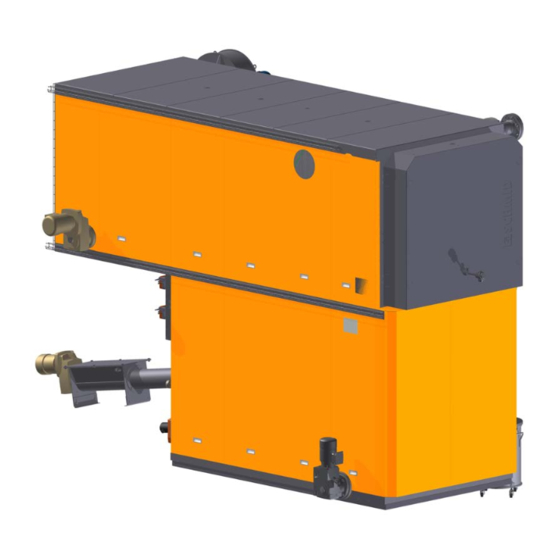
Page 24: Design Of The Moving Grate Combustion System
2 Description UTSR Design of the moving grate combustion system The automatic wood combustion system consists of the following system components: 10,26 13,15 Fig. 5 Design of the moving grate combustion system UTSR moving grate combustion system D-24 1.8 en... - Page 25 2 Description UTSR Item Designation Function Fuel transport, inlet Inlet for fuel, e.g. via stoker screw Combustion grate Consists of a vault, refractory lining, and a moving grate Hot water boiler Heating the hot water Boiler door Access to the hot water boiler Flue gas dedusting (cyclone Usually by means of a multi-cyclone separator)
-
Page 26: Automatic Boiler Tube Cleaning (Optional
2 Description UTSR Item Designation Function Refractory lining sensor Measures the temperature of the refractory lining (possible from UTSR 700 and larger) Combustion chamber temperature Measures the temperature in the combus- sensor tion chamber and regulates the supply air Boiler drain KE for draining the water from the boiler sensor (lambda sensor) Measures the oxygen content in the flue... -
Page 27: Automatic Ignition (Optional
2 Description UTSR 2.4.2 Automatic ignition (optional) Automatic ignition is performed with an industri- al hot air blower installed on the side of the com- bustion system. The fuel is ignited automatically directly in the combustion chamber. The auto- matic ignition consists of: •... -
Page 28: Temperature Safety Valve
2 Description UTSR 2.4.4 Temperature safety valve The thermal process safeguard is designed for discharging the boiler idle capacity, e.g. in the event of failure of the boiler pump or a power failure. In the event of excess temperatures the thermostatic valve opens automatically and cools the boiler. Discharge must be effected through a heat-resistant pipe. - Page 29 A drinking water separator must be installed in the extinguishing water supply in compliance with specific national regulations. An annual functional check must be carried out on the thermal process safeguard. This inspection work may only be carried out by service personnel of Schmid energy solu- tions. Operating range (kW)
-
Page 30: Flue Gas Recovery (Option
2 Description UTSR 2.4.5 Flue gas recovery (option) The flue gas recovery unit is a system that recirculates part of the flue gas to the primary air zone (up to 900kW) or the primary and secondary air zone (from 1200kW). This reduces the combustion chamber temperature. -
Page 31: Under-Grate De-Ashing (Option
2 Description UTSR Ø flue gas recovery Ø flue gas recovery Boiler size Boiler size duct [mm] duct [mm] UTSR-700-900 UTSR-5000 500 / 4x 300 UTSR-1200 250 / 2x 200 UTSR-6500 500 / 4x 300 UTSR-1600 250 / 2x 200 2.4.6 Under-grate de-ashing (option) Ash is removed automatically under the moving... -
Page 32: Flue Gas Filter System (Option
2 Description UTSR Before carrying out any maintenance work on the automatic boiler tube cleaning system, the compressed air tank of the cleaning system must be disconnected from the air supply (e.g. by closing the ball tap or releasing the quick-action coupling on the compressor). -
Page 33: Inlet Design Variants
2 Description UTSR Inlet design variants For combustion of wood chips, shavings etc., in accordance with the order confirmation and system overview. Water-cooled grate inlet for the ESC hydraulic push- er and HFE hydraulic horizontal conveyor unit as well as STO from UTSR-3200 Transition to the HFE hydraulic horizontal conveyor unit Grate inlet to the stoker screw... -
Page 34: Technical Data
2 Description UTSR Technical data 2.8.1 Dimensions (subject to technical changes) Fig. 14 Dimensions Capacity (kW) 1150 1150 2600 1400 1200 1150 1150 2600 1400 1200 1150 1150 2600 1400 1200 1250 1250 2650 1400 1250 1250 1250 2650 1400 1250 1440 1440... - Page 35 2 Description UTSR Capacity with- with- (kW) 3373 2943 1600 1060 1800 3373 2943 1600 1060 1800 3573 3143 1600 1260 1800 3792 3343 1800 1260 1800 3792 3343 1800 1260 1800 4292 3843 2300 1260 2300 4292 3843 2300 1260 2300 4292...
-
Page 36: Connection Sizes
2 Description UTSR 2.8.2 Connection sizes Fig. 15 Connection sizes Capacity (kW) (mm) (mm) (mm) (mm) (mm) (mm) (mm) (mm) (mm) (mm) (mm) (mm) 2320 1" 2320 1" 2320 1" 2340 1" 2340 1" 2670 1 ¼“ 2670 1 ¼“ 2670 1 ¼“... -
Page 37: Weights
2 Description UTSR 2.8.3 Weights Weight of Empty Grate Separator Capacity boiler incl. Operating weight weight weight (kW) AKP door weight (kg) (kg) (kg) (kg) (kg) 4800 2610 1920 5500 4800 2610 1920 5500 4860 2610 1920 5550 5650 3005 2295 6550 5670... -
Page 38: Planning Values
2 Description UTSR 2.8.4 Planning values UTSR series UTSR-180 UTSR-240 UTSR-300 UTSR-360 UTSR-450 in compliance with EN 303-5: 2012 Heat generation calculation basis: Nominal heat capacity Heat capacity range 30-100% 54-180 72-240 90-300 108-360 135-450 Permissible operating overpressure Permissible operating temperature °C Minimum return line temperature °C... - Page 39 2 Description UTSR UTSR series UTSR-180 UTSR-240 UTSR-300 UTSR-360 UTSR-450 in compliance with EN 303-5: 2012 Capacity at lowest capacity HG 0.6** 0.6** 0.6** 0.6** 0.5** Capacity at nominal heat capacity PE 1.1** 1.3** 1.4** 1.4** 1.5** Capacity at lowest capacity PE 0.7** 0.7** 0.6**...
- Page 40 2 Description UTSR UTSR series UTSR-550/500 UTSR-550 in compliance with EN 303-5: 2012 Flue gas temperature at the lowest capacity °C Flue gas flow rate at nominal capacity HG 410* 410* Flue gas flow rate at the lowest capacity HG 110* 110* Flue gas flow rate at nominal capacity PE...
- Page 41 2 Description UTSR UTSR series in UTSR- UTSR- UTSR- UTSR-700 UTSR-900 UTSR-995 line with EN 303-5: 2012 1200 1600 2000 Heat generation calculation basis: Nominal heat capacity 1200 1600 2000 Heat capacity range 30-100% kW 210-700 270-900 300-995 360- 480- 600- 1200 1600...
- Page 42 2 Description UTSR UTSR series in UTSR- UTSR- UTSR- UTSR-2400 UTSR-3200 line with EN 303-5: 2012 4200 5000 6500 Heat generation calculation basis: Nominal heat capacity 2400 3200 4200 5000 6500 Heat capacity range 30-100% kW 720-2400 960-3200 1260- 1500- 1950- 4200 5000...
-
Page 43: Transport
3 Transport Transport All of the products offered by Schmid AG energy solutions are transported by our own specialists and delivered to the correct location. The components of the system are protected against corrosion for transport and storage. The components of the combustion system are delivered separately as follows: •... - Page 44 3 Transport WARNING! The boiler door can open accidentally during transport and cause injury to the head and upper body. The boiler door must be closed before lifting the boiler. Never stand between the lifted boiler and a wall - risk of crushing. UTSR moving grate combustion system D-44 1.8 en...
-
Page 45: Lifting Loads
Alternatively, the system components can also be unloaded using a forklift. In this case make sure to tell the Schmid AG energy solutions project lead. In this case the compo- nents are supported with pallets or squared timber during truck loading. -
Page 46: Installation, Commissioning
The electrical assembly and installation is not included within the Schmid AG energy solutions scope of supply. DANGER! Danger from electrical energy. -
Page 47: Commissioning
4 Installation, commissioning Commissioning All Schmid AG energy solutions products are normally taken into operation by our trained staff. An essential part of the commissioning process includes the instruction of the future equipment operators. The equipment operators must be present during commissioning. The personnel should be familiar with the instruction manual prior to commissioning. -
Page 48: Requirements For Circulating Water Up To 110
4 Installation, commissioning 4.2.1 Requirements for circulating water up to 110° In order to prevent damage, particularly due to scaling in the hot water boilers circu- lating water in new and refills must fulfil the following conditions: Characteristic Value Notes Total water hardness Max 0.2°... -
Page 49: Heating The Combustion Chamber
4) Once dry, the refractory should be heated at a rate of 50°C/h until it reaches the maximum temperature. We recommend letting specialists from Schmid AG energy solutions or from another specialised service provider heat up the moving grate combustion system for the first time. -
Page 50: Operation
5 Operation Operation General instructions The moving grate combustion system can be ignited and controlled via a central control unit (optional). If the automatic ignition system does not work or is not installed, the system must be ignited manually. The moving grate combustion system may only be operated in a safe, functional and good condition. -
Page 51: System Operation
5 Operation 5.1.1 System operation To guarantee minimum system wear, continuous operation is necessary. With contin- uous operation, the thermal loads from repeated cooling and heating are prevented, which has a positive effect on the service life of the entire system. With regard to the set number of activation/deactivation operations per day and the minimum combustion time, in Switzerland the regulations of the canton must be taken into account. -
Page 52: Switching The Combustion System On
5 Operation Switching the combustion system on DANGER! Explosion hazard due to deflagration! An overfilled combustion chamber can create an explosive atmosphere, which can cause serious injury when lit. Empty the combustion chamber before firing. Never use fire accelerants (petroleum or similar) when lighting the fire. The detailed description of how to switch on the combustion system is given in Register "C User manual, Control unit", section "4.2 Automatic mode". -
Page 53: Correct Manual Lighting
5 Operation 5.2.1 Correct manual lighting Materials: Firewood and wax-soaked wood shavings or wood chips. Never use fire accelerants (e.g. petroleum or similar) for lighting - risk of burns. In addition to these highly flammable ma- terials, add middle sized and large pieces of firewood, observing the rule of thumb: "From fine to coarse, from soft to hard"... -
Page 54: Emergency Shut Down
5.4.2 Machine control unit The entire system can only be operated via the control unit. It is set up by Schmid AG energy solutions personnel during the commissioning process (see «4 Installation, commissioning»). Changes to the settings may only be made by Schmid AG energy solutions service personnel. -
Page 55: Recommissioning After A Longer Interruption
5 Operation Recommissioning after a longer interruption No special measures are necessary if recommissioning after a period of downtime of up to one year. After longer periods of downtime, proceed according to «4.2 Commissioning». During commissioning the moving grate combustion system should be checked for flawless operation without fuel. -
Page 56: Maintenance
Maintenance contract In order to prevent faults and defects to the system, and to ensure optimal combustion, we recommend maintenance of the system by Schmid AG energy solutions either annu- ally or every 4000 hours of operation. Schmid AG energy solutions offers maintenance contracts with different performance levels. -
Page 57: Cleaning
6 Maintenance Cleaning WARNING! Risk of injury when entering the combustion chamber. Always secure the combustion chamber door. Before entering the combustion chamber always secure the combustion chamber door with the personal padlock. WARNING! Risk of injury due to rotating parts. Before entering the combustion chamber, switch off the grate de-ashing screw on the maintenance switch and secure with the personal padlock to prevent reactivation. -
Page 58: Clean Boiler Passes
6 Maintenance WARNING! Surfaces and interior are very hot and can cause burns. Before cleaning allow the combustion system to cool. Always wear personal protective equipment. Secure the system against accidental activation. WARNING! Dust and fly ash can negatively influence breathing and cause irreversible damage to lungs and respiratory tracts. -
Page 59: Clean Upper Vault
6 Maintenance 6.3.2 Clean upper vault Procedure: 1. Open the cover. 2. Push the ash into the oven. 3. Pull the ash on the top vault to the front. WARNING! The interior is very hot and can cause burns. Before cleaning allow the combustion system to cool. -
Page 60: Clean Ash Removal Box
6 Maintenance 6.3.3 Clean ash removal box Procedure: 1. Open the cover. 2. Push the ash to the rear, inward and suction off. 6.3.4 Clean fan Procedure: 1. Open cleaning opening. 2. Clean the fan hub with a brush (preliminary cleaning using the square brush, final cleaning with a round brush). -
Page 61: Clean Lower Vault
6 Maintenance 6.3.5 Clean lower vault Procedure: 1. Remove panel cover. 2. Open the door. 3. Put on heat resistant gloves and remove the door inserts. 4. Push the ash rearward into the combustion chamber. UTSR moving grate combustion system 1.8 en D-61... -
Page 62: Clean The Moving Grate
3. Clean the grate bars mechanically and check for damage. 4. Refit the grate bars in the same sequence. Do not confuse the sequence of the rows when refitting. The grate bars and rows may only be changed by Schmid AG energy solutions service personnel. 6.3.7 Clean lower grate Procedure: ... -
Page 63: Maintenance Overview
6 Maintenance Maintenance overview The maintenance and inspection data are based on continuous operation. If the require- ment is not fulfilled within the corresponding period, the period can be extended. However, a complete overhaul must be performed every two to three years. 10,26 13,15 Fig. - Page 64 6 Maintenance The key to the drawing above is contained in section «2.4 Design of the moving grate combustion system» Maintenance tasks Visually inspect the combustion chamber (31) and fire appearance. Check the flue gas temperature 6.5.1 Listen for unusual noise in the motor or other unusual noises Check the fill level of the ash container.
- Page 65 6.5.2 Check the thermal extinguishing water valve Only have Check the back fire thermostat carried out Check the rotary valve or back fire protection by Schmid slide AG energy Check the differential pressure gauge solutions Check the safety temperature limiter...
- Page 66 6 Maintenance Maintenance tasks Have the hoses checked by a competent person In compli- (hydraulic specialist) for leaks and brittle areas ance with EN ISO 4413 Oil change, hydraulic units 4 years or 16,000 hours Observe the of operation manufactur- er's specifi- cations Replace all hydraulic hoses...
-
Page 67: Maintenance Tasks
Please coordinate the inspection date with our customer service depart- ment as early as possible. In the event of deviation from the values determined during commissioning, the system must be cleaned or Schmid AG energy solutions customer service must be contacted. 6.5.2 Clean the O... -
Page 68: Maintenance Work On Components With Drive Units
6 Maintenance 6.5.4 Maintenance work on components with drive units All separately deactivating drives are equipped with a maintenance switch and can be disconnected from the mains for maintenance purposes. No maintenance switches are permitted for electrical drive units which cannot be indi- vidually deactivated for safety reasons. -
Page 69: Oil Hydraulics
6 Maintenance 6.5.6 Oil hydraulics WARNING! High pressures, incorrect assembly or brittle hydraulic lines can result in injury caused by high pressure streams of fluid! Check the hydraulic lines regularly in accordance with the maintenance schedule. If defective hydraulic lines or leaks are discovered, they must be repaired immediately. The hydraulic lines must be checked and replaced every six years by a hydraulics engi- neer. - Page 70 6 Maintenance Oil level check/oil change Check the oil level monthly in the inspection window of the hydraulic power unit. The oil level should be kept at the "max." mark when all cylinders are retracted. Change oil according to manufacturer's spec- ifications in the supplier documentation.
-
Page 71: Lubrication
6 Maintenance 6.5.7 Lubrication All the parts of the system are lubricated prior to delivery. Periodic lubrication is indis- pensable for fault-free operation of the system and prevents expensive repairs (refer to the maintenance table). Fig. 21 Lubrication points UTSR moving grate combustion system 1.8 en D-71... - Page 72 6 Maintenance Item Maintenance tasks Lubricant Lubricate flanged bearings, roller Multi-purpose grease, lithium saponified, chains, and bearing points on screw e.g. High-performance lubricating grease conveyors Motorex FETT 3000 art. no. 6000.4374 Grease bearings on flue gas fans, Special high-temperature grease, (up to 7.5 generally 11 kW capacity and above kW, usually permanently lubricated), e.g.
-
Page 73: Disassembly And Disposal
Disassembly and disposal Disassembly Schmid AG energy solutions strongly recommends that disassembly be carried out by our specialists. Schmid AG energy solutions assumes no liability for injury, damage to machinery or buildings resulting from improper disassembly performed by third parties. WARNING! Improper disassembly can cause damage to persons and to the building! Before disassembly, it is essential to disconnect the power supply. -
Page 74: Spare Parts
Under certain circumstances, the installation and use of such products may have a negative impact on and thus affect the safety of the system's design fea- tures. In principle, only original components or those that are approved by Schmid AG energy solutions may be installed in the system. Note: The following spare parts lists correspond to standard systems (valid in March 2014). -
Page 75: Utsr Moving Grate Combustion System
8 Spare parts UTSR moving grate combustion system 16,17 18,19 4,5,6 1,2,3 41,42,43 9,10 28,29 Fig. 22 Spare parts for the UTSR moving grate combustion system UTSR moving grate combustion system 1.8 en D-75... -
Page 76: Utsr 180-240
8 Spare parts 8.3.1 UTSR 180-240 Item Quantity Description Article no. Notes Grate bar medium cam 3 mm, 330/ 2000.2135 65 GG20 Vault firebrick M60t pressed 4000.6792 Bronze for grate carriage, 4000.4289 For grate carriage 60x60x400mm LB50 Bronze ø82/ø35x36 mm, cylinder 4000.5090 For grate carriage cyl-... -
Page 77: Utsr 300-360
8 Spare parts 8.3.2 UTSR 300-360 Item Quantity Description Article no. Notes Grate bar medium cam 3 mm, 2000.2135 330/65 GG20 Vault firebrick M60t pressed 4000.6793 End brick A45t pressed 4000.6794 Bronze for grate carriage, 4000.4289 For grate carriage 60x60x400mm LB50 Bronze ø82/ø35x36 mm, cylinder 4000.5090 For grate carriage cylin- guide for cylinder 50/25... -
Page 78: Utsr 450-550
8 Spare parts Item Quantity Description Article no. Notes 2.42 m Gasket KERA, 30x30mm (550°) 6000.1344 Side door seal type SC Safety interlock AZM 161, AZM 2000.7217 161SK-12/03RK-024G 8.3.3 UTSR 450-550 Item Quantity Description Article no. Notes Grate bar long cam 5.5 mm, 450/ 2000.4426 64.5 mm heat resistant Grate bar long cam 5.5 mm, 450/... -
Page 79: Utsr 700-900
8 Spare parts Item Quantity Description Article no. Notes Insulation panel, 3x235x336mm 4000.4119 Mica glass, Ø48x0.5mm 2000.2070 For inspection window Ø50 Gasket KERA, Ø40 (550°) type SR 6000.1305 Seal over the first 0.71 m grate bar 1.71 m Gasket KERA, 22x22mm (1050°) 6000.1371 Seal for combustion type IC chamber door... - Page 80 8 Spare parts Item Quantity Description Article no. Notes Bronze ø99/ø50 x 37 mm, cylinder guide 4000.5091 For cylinder for cylinder 63/40 stroke =200 guide under- grate de-ash- Double-acting hydraulic cylinder, ZD0 2000.0617 For under- C1-80/40-200-R-Viton GK1-35 grate de-ash- Supply air fan, CMP 922-2T-3 2000.1191 2.2 KW/2880 Silencer on the suction side clear width...
-
Page 81: Utsr 1200
8 Spare parts 8.3.5 UTSR 1200 Item Quantity Description Article no. Notes Grate bar wide, 450/125 mm 2000.2139 Heat resistant Grate bar long cam 5.5 mm, 450/64.5 2000.4426 Heat resistant Grate bar long cam 5.5 mm, 450/62.5 2000.4435 Number is defined mm heat resistant when installing Grate bar long cam 3.5 mm, 450/64.5... -
Page 82: Utsr 1600
8 Spare parts Item Quantity Description Article no. Notes 8.1 m Gasket Kera, Ø40 (600°) type SC 6000.1305 Seal between grate and boiler 1.1 m Gasket Kera, Ø40 (600°) type SC 6000.1305 Seal over the first grate bar 2.1 m Gasket Kera, 25x25mm (1200 °) type 6000.1370 Seal grate door 1.9 m... -
Page 83: Utsr 2000
8 Spare parts Item Quantity Description Article no. Notes Refractory lining sensor, Pt10Rh-Pt- 2000.0183 Ø15x600mm Damper actuator NM24A with UL 2000.3825 perm., NM24A-C110.1, AC/DC 24 V, 10 Nm Differential pressure sensor, SDF- 2000.0359 Incl. low-pass filter 50-250U 0.3 m Plastic hose, clear width ø5x1.5mm 2000.1357 For differential pres- sure gauge Tube brush, Ø... - Page 84 8 Spare parts Item Quantity Description Article no. Notes Double-acting hydraulic cylinder, 2000.0617 For under-grate de- ZD0 C1-80/40-200-R-Viton GK1-35 ashing Supply air fan, CMP 922-2T-3 2000.1191 2.2 KW/2880 rpm Supply air fan, CMP 1128-2T-5.5 2000.1192 4 kW/2880 rpm Silencer on the suction side clear 1000.2197 Fan CMP 922-2T-3 width ø200 Silencer on the suction side clear...
-
Page 85: Utsr 2400
8 Spare parts 8.3.8 UTSR 2400 Item Quantity Description Article no. Notes Grate bar wide, 450/125 mm 2000.2139 Heat resistant Grate bar long cam 5.5 mm, 450/ 2000.4426 Heat resistant 64.5 mm Grate bar long cam 5.5 mm, 450/ 2000.4435 Number is defined 62.5 mm heat resistant when installing Grate bar wide, 450/123 mm heat... -
Page 86: Utsr 3200
8 Spare parts Item Quantity Description Article no. Notes Mica glass, Ø048x0.5mm 2000.2070 For inspection window Ø50 11.25 Gasket Kera, Ø40 (600°) type SC 6000.1305 Seal between grate and boiler 2.1 m Gasket Kera, 25x25mm (1200 °) 6000.1370 Seal grate door type IC 2.1 m Gasket Kera, 25x25mm (1200 °) -
Page 87: Utsr 4200 - 6500
8 Spare parts Item Quantity Description Article no. Notes Refractory lining sensor, Pt10Rh-Pt- 2000.0183 Ø15x600mm Thermocouple sheath element; 2000.0444 2400, 3200 TCMT c, 2000 mm Damper actuator NM24A with UL 2000.3825 perm., NM24A-C110.1, AC/DC 24 V, 10 Nm Differential pressure sensor, SDF-50- 2000.0359 Incl. -
Page 88: Automatic Boiler Tube Cleaning Unit
8 Spare parts Automatic boiler tube cleaning unit Fig. 23 Automatic boiler tube cleaning unit UTSR 180...550 Item Quantity Description Article no. Notes Valve diaphragm Viton, G 1 1/2 24/DC 2000.3468 Hose to AKP, Ø64/50, L= 85mm, black 2000.5310 Hose clips Ø60-63mm 2000.5281... - Page 89 8 Spare parts UTSR 3200, 5000 Item Quantity Description Article no. Notes Valve diaphragm, Viton, ASCO G 1 1/2 2000.3468 24/DC Hose to AKP, Ø64/50, L= 85mm, black 2000.5310 Hose clips Ø60-63mm 2000.5281 UTSR moving grate combustion system 1.8 en D-89...
-
Page 90: Automatic Ignition Unit
8 Spare parts Automatic ignition unit Fig. 24 Automatic ignition unit UTSR 150...550 (with single stoker) Item Quantity Description Article no. Notes Ignition blower, BAK-Eron 230V/ 3400W 2000.4304 3.4 kW For Leister Elektron heating unit 2A, Leis- 2000.1288 ter Elektron 2A Typ32, 3st UTSR 150...550 (with double stoker) Item Quantity Description... -
Page 91: Back Fire Protection Bra
8 Spare parts Back fire protection BRA Fig. 25 Back fire protection BRA UTSR 150-550 (with single stoker) Item Quantity Description Article no. Notes Extinguishing water valve, AVTA 2000.0956 Complete, probe, cor- 20 3/4 inch 50-90°C rugated tube and valve UTSR 150-4200 (with double stoker) Item Quantity Description... -
Page 92: Flue Gas Recovery (Recirculation
8 Spare parts Flue gas recovery (recirculation) Fig. 26 Flue gas recovery (example illustrated) Item Designation Recirculation fan Check flap valve Non-return valve up to 900 kW, rotary slide valve from 1200 kW Temperature monitoring up to 900kW Primary air zone Secondary air zone UTSR moving grate combustion system D-92... - Page 93 8 Spare parts Dimensions, articles numbers Boiler size Recirculation fan Check flap valve Swing-type check valve Item no. Item no. Item no. UTSR-150 UTSR-180 4001.6865 ø130 UTSR-240 UTSR-300 UTSR-360 4000.9955 RHS-160 2000.6836 FK 160 UTSR-450 UTSR-550/500 4001.6846 ø150 UTSR-550 UTSR-700 4001.4850 ø200 UTSR-900...
- Page 94 8 Spare parts Dimensions, articles numbers Boiler size Rotary slide valve Temperature monitoring Item no. Item no. UTSR-150 UTSR-180 UTSR-240 UTSR-300 UTSR-360 none none 2000.0416 PT 100 UTSR-450 UTSR-550/500 UTSR-550 UTSR-700 UTSR-900 UTSR-995 UTSR-1200 4001.1697 ø200 UTSR-1600 UTSR-2000 UTSR-2400 none none 4000.1665 ø250...
Need help?
Do you have a question about the UTSR 180 and is the answer not in the manual?
Questions and answers