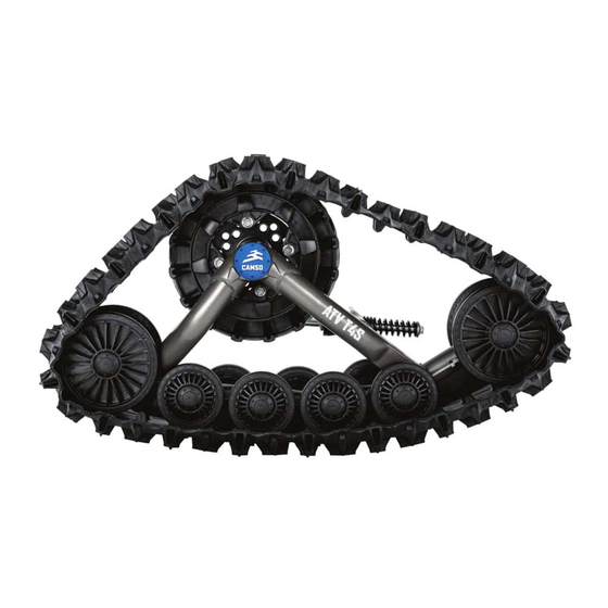
CAMSO ATV T4S Owner's Manual
Track system for all-terrain vehicles
Hide thumbs
Also See for ATV T4S:
- Installation manuallines (16 pages) ,
- Adjustments (10 pages) ,
- Installation manuallines (20 pages)
Table of Contents
Advertisement
Quick Links
Advertisement
Table of Contents

Related Manuals for CAMSO ATV T4S


Summary of Contents for CAMSO ATV T4S
- Page 1 OWNER’S MANUAL CAMSO ATV T4S TRACK SYSTEM FOR ALL-TERRAIN VEHICLES 1099-01-1054...
- Page 2 Please read carefully each part of this document as well as the model specific Installation Guidelines prior to assembling, installing and using the Track System. CAUTION: Longevity of the Camso ATV T4S Track System components is directly linked to the way the System is used. Sportive driving, rapid direction changes and repeated fast turns (especially on power steering vehicles) are not advised.
-
Page 3: Table Of Contents
TABLE OF CONTENTS INTRODUCTION ................1 SYMBOLS AND SIGNAL WORDS . -
Page 4: Introduction
However, during normal operating conditions, matter where or in what conditions, get there and vehicle speed should be reduced compared to a back safely with your Camso track systems. wheeled vehicle. Ready to benefit from optimal traction, mobility, stability, and flotation? Let’s go make tracks! -
Page 5: Safety
CAUTION: Do not remove the warning sticker from the frame. If a sticker is damaged, have it replaced assembly bolt under any circumstance. The bolt is by an authorized Camso dealer. used to assemble and align the tensioner with the frame. Tensioner re-alignment is necessary if this bolt is loosened. - Page 6 ATV equipped with the Carrying a passenger, a load or attaching a tow can Camso ATV T4S System by Camso. It is cause the ATV to be less stable, and affect usability mandatory that every user takes the time to of the vehicle.
-
Page 7: Operating Instructions
OPERATING INSTRUCTIONS OPERATING INSTRUCTIONS • A BAD break-in period can generate smoke, odors of burned rubber as well as plastic deposits on the sprocket and/or the frame. HINTS AND TIPS • Before leaving for an excursion, make sure to bring with you the following: 13 mm, 14 mm, 15 mm, 16 mm, 17 mm, and 19 mm wrenches and WARNING sockets, an axe, a shovel, a tow cable, a lifting... - Page 8 OPERATING INSTRUCTIONS STEEP DESCENTS DESCENDING AND BEING STUCK IN REVERSE CAUTION: It is not advisable to change direction CAUTION: If the rear Track Systems get stuck in the during steep descents. This can lead to a serious snow, avoid moving or towing the vehicle in reverse malfunction of the ATV’s steering system and Track to ease it from its position, as this could lead to a Systems.
- Page 9 OPERATING INSTRUCTIONS DRIVING OVER AN OBSTACLE TALLER DRIVING OVER A STEEP RIDGE THAN 30 cm [12 in] CAUTION: It is not advisable to attempt to drive over an obstacle, such as a tree trunk, big rock or steep CAUTION: It is not advisable to attempt to drive ridge that could lodge itself between the front and over an obstacle taller than 30 cm [12 in], such as a the rear Track Systems and immobilize the vehicle.
- Page 10 OPERATING INSTRUCTIONS LOCATION OF TOWING CABLE TOWING A VEHICLE OUT OF THE SNOW CAUTION: If your vehicle must be towed out of the CAUTION: If your vehicle must be towed out of the snow, do not secure the towing cable on the Track snow, never tow it in the direction in which you were Systems.
- Page 11 EXCEEDING THE ANTI- ROTATION STROKE ON ROUGH TERRAIN CAUTION: Never exceed anti-rotation stroke of front or rear Track Systems. System or vehicle failure may occur. Camso recommends always riding on terrain that fully supports the Track System. TRACK SYSTEMS OPERATING...
-
Page 12: Specifications
SPECIFICATIONS SPECIFICATIONS OFFSETS ON VEHICLE Installation of a Track System on a vehicle creates TORQUE SPECIFICATIONS offsets in length, height and width. The offsets are illustrated in the figure below and their dimensions The table below contains the recommended torque are specified in the accompanying table. -
Page 13: Adjustments
ADJUSTMENTS ADJUSTMENTS NOTE : Before each measurement, temporarily apply light pressure to the front of the track to make sure that it stays flat on the ground. CAUTION: Track System adjustments must be verified after first use on the vehicle, and then at •... -
Page 14: Angle Of Attack - Rear Systems
ADJUSTMENTS NOTE: Once angle of attack on front Systems is set, • Loosen nut (3) compressing stabilizing rod verify once again to confirm adjustment. spring. See Figure 9. Figure 7 Figure 9 NOTE: Use narrow part of adjusting template, BASIC TUNING (Front Track Systems) provided with stabilizing arm, to make adjustment. - Page 15 ADJUSTMENTS • IMPORTANT: Double-check • Loosen jam nut (5). Turn stabilizing arm (1) to minimum distance between nut and stabilizing adjust length of rod end (6) so that rubber cone arm guide. Re–adjust as needed. Figure 12. (7) applies light pressure on anti–rotation retainer (4).
-
Page 16: Alignment
ADJUSTMENTS BASIC TUNING (Rear Track Systems) • The adjustment incorrect when stabilizing arm’s rubber cone is compressed and deformed. The stabilizing arm’s spring is then difficult or impossible to turn by hand. TRACK SYSTEM REMOVAL Figure 18 CAUTION: Leaving anti-rotation anchor brackets attached to the suspension arms, after Dimension A: distance between inner front wheels... - Page 17 ADJUSTMENTS Measure A: Measure the distance inside the front Measure B: Measure the distance inside the rear Ø202 mm wheels on the front Track Systems. Ø202 mm wheels on the front Track Systems. See See figures 20, 21 and 22. figures 23, 24 and 25.
-
Page 18: Track Tension
ADJUSTMENTS TRACK TENSION NOTE: The track tension testing tool, shown below in Figure 28, can be purchased through an authorized Camso dealer. Part #2000-00-3125. WARNING The tensioner assembly bolt must never be loosened while adjusting the track tension. This bolt is designed for assembly and alignment of the tensioner with the frame. -
Page 19: Tracks - Installation Direction
STORAGE TRACKS - INSTALLATION DIRECTION Before storing the Track System, it is important to perform the recommended annual maintenance Front track: can be installed in both direction. tasks. Refer to the maintenance chart of page 17, Figure 30. section Intervals - column 200 Hrs / Annual. To avoid deterioration of mechanical components due to potential prolonged exposition to water, sand, salt or other similar contaminant, it is... -
Page 20: Maintenance
MAINTENANCE MAINTENANCE CAUTION: Camso recommends not using a brake WARNING cleaning solvent to clean the Track System. This may damage sealing components and stickers. Do not insert hands or feet into or near the System unless the engine is off, and the vehicle is The maintenance schedule has been established stopped with the security brake engaged. - Page 21 MAINTENANCE CAUTION: Some of the repair or maintenance • Bolt Torque: Check the torque of critical bolts tasks require petroleum-based identified in the exploded views of the system. products, such as oils or greases, that should not Refer to the central pages of the User Manual. be handled directly with unprotected hands.
- Page 22 NOTE: The Wheel extractor shown below in Figure 33 • Wear: Check wear of sprockets on the can be purchased through an authorized Systems. Replace if wear is too great. Refer to Camso dealer. Part #2000-00-1050. “Wear” in the Maintenance section on page 24. Anti-rotation • Lubrication:...
-
Page 23: Lubrication
MAINTENANCE LUBRICATION WHEEL SEALS & WHEELS HUB SEAL HUB - SPEED SLEEVE TRACK TENSIONER ANTI-ROTATION ARM... - Page 24 MAINTENANCE LUBRICATION Camso recommends pouring 5 cc of oil under wheel caps, at every maintenance interval. This The maintenance chart on page 17 includes will help minimize presence of contaminants and lubrication maintenance to perform on the extend wheel bearing life.
- Page 25 MAINTENANCE REFERENCE “C” REFERENCE “E” LUBRICATION OF HUB SPEED SLEEVE STABILIZING ARM LUBRICATION Apply 1.5 to 2 cc of grease over the entire width Clean and apply spray lubricant all around Rear and circumference of the hub Speed Sleeve. Stabilizing arm compression spring on vehicles with a rigid rear axle suspension.
-
Page 26: Wear
MAINTENANCE Anti-rotation LUBRICATION OF STABILIZING ARM ROD ENDS Verify wear on Stabilizing arm ball joint to make Clean and apply spray lubricant to rod end on sure that it is not seized or too loose. Figure 35. Stabilizing arms. CAUTION: A damaged ball joint can impede Track System adjustments and result in damages to the Track System and to the vehicle if not replaced. - Page 27 MAINTENANCE Wheels Track guide Verify wear on wheels, especially on interior Verify wear on Track guide by measuring width of guidance strip. If internal plastic structure is guide rails. If rail dimensions, illustrated in Figure visible (Figure 38-2) -- (new wheel Figure 38-1), 40, are less than 5 mm at any point along Track rubber coating is worn away and wheel must be guide, replace part.
-
Page 28: Troubleshooting
TROUBLESHOOTING TROUBLESHOOTING PROBLEM POTENTIAL CAUSE CORRECTION Try to free the wheel and replace it if Blocked wheel necessary Correct Track System alignment. Refer to Misalignment of System Overheating of System Adjustments section in User Manual guiding components (burned rubber Vary your turning radius and seek areas plastic odor) Constant turning that can help lubricate the System... - Page 29 TROUBLESHOOTING PROBLEM POTENTIAL CAUSE CORRECTION Remove any debris that could prevent Presence of debris in the system proper operation of the System Severe and localized wear on a wheel (flat Replace part spot) Remove ice/snow build-up. Storing the vehicle at temperatures higher than 0°C Frozen sprocket or wheel might be required.
-
Page 30: 2-Year Limited Warranty
Camso. ® The Camso ATV T4S Track System is covered by a 8) Damage resulting from an accident, incident, manufacturer warranty (warranty). -
Page 31: Ce'' Declaration Of Conformity
Camso Inc. MANUFACTURER: 4162, rue Burrill, Local A, Shawinigan (Québec), Canada G9N 0C3 ADDRESS: WEB SITE: www.camso.co HEREBY DECLARE THAT THE PRODUCT SERIES: ATV T4S Track System PRODUCT: CUSTOMER: IS IN CONFORMITY WITH THE FOLLOWING STANDARDS: NUMBER: TITLE: DATE: IEC/IEEE 82079-1... -
Page 32: Environment
Track Systems come to the end of their life. PATENTS The Camso ATV T4S System is covered by the following patents: • CA 2 405 908 • CA 2 493 181 • CA 147 901 •... -
Page 33: Torque Specifications
TORQUE SPECIFICATIONS TORQUE SPECIFICATIONS FRONT SYSTEMS... - Page 34 TORQUE SPECIFICATIONS REAR SYSTEMS...
- Page 35 TORQUE SPECIFICATIONS TORQUE THREAD LOCKER 50 N-m 70 N-m - REAR - INDEPENDENT SUSPENSION 75 N-m 40 N-m TORQUE THREAD LOCKER 50 N-m - REAR - RIGID SUSPENSION 50 N-m...
Need help?
Do you have a question about the ATV T4S and is the answer not in the manual?
Questions and answers