
Subscribe to Our Youtube Channel
Related Manuals for CAMSO POLARIS 5000-05-0045-MAN


Summary of Contents for CAMSO POLARIS 5000-05-0045-MAN
- Page 1 INSTALLATION GUIDELINES GUIDE D’INSTALLATION CAMSO TRACK SYSTEMS FOR ALL-TERRAIN / SIDE-BY-SIDE VEHICLES SYSTÈMES DE CHENILLES CAMSO POUR VÉHICULES TOUT-TERRAIN ET CÔTE À CÔTE POLARIS 5000-05-0045-MAN VERSION S...
- Page 2 Track System which will not be covered under normal warranty. TECHNICAL SUPPORT If your dealer or distributor is unable to solve a problem related to the System, you may contact the Camso support team from Monday to Friday.
-
Page 3: Symbols And Signal Words
No matter where or in what conditions, get there and back safely with your Camso track systems. Ready to benefit from optimal traction, mobility, stability, and flotation? Let’s go make tracks! -
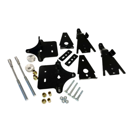
Page 4: Parts List
PARTS LIST CAUTION: Before beginning the installation, make sure that you have received all the components included in the parts lists below. ITEM PART # DESCRIPTION 1004-05-0670 FRONT BRACKET KIT ANTI-ROTATION FRONT BRACKET FRONT COVER 1033-10-0050 HEX BOLT - HCS, M10-1.5X50, 8.8, ZP, DIN931 1074-10-0001 NYLON NUT - FNN, M10-1.5, 8, ZP, DIN6926 ITEM... -
Page 5: Torque Specifications
PREPARATION TORQUE SPECIFICATIONS 1. Set each Track System unit near the position Recommended torque specifications according to indicated by the sticker affixed on the frame. bolt size and grade. GRADE DIMENSION lb-ft M6-1.0 M8-1.25 M10-1.5 M12-1.75 Fig. 2 NOTE: Use a thread locker (Loctite 262 or equivalent) at the specific points of the System indicated in the User Manual’s exploded views. - Page 6 4. Insert M10x80mm bolt (B6), provided in the 6. Insert the M10x65mm bolt (B5) in the bracket hole installation kit, in the rear anchor bracket (B1-B2) aligned with C-shaped hooks, install spacer bushing as shown in Fig. 4 (B7) and nut (B10) on bolt. Tighten assembly to 50 N•m [37lb•ft] of torque.
- Page 7 8. Tighten assembly to 50 N•m [37 lb•ft] of torque. See 10.Attach stabilizing rod (2) to anchor bracket (1), using Fig. 9 the long spacer bushing (B8), the short spacer bushing (3), flat washer (4) and nut (5). Torque to 70 N•m [52 lb•ft].
- Page 8 FRONT TRACK SYSTEM 5. Position bottom part of anchor bracket (A1) under lower suspension arm. Position top part (A2) over INSTALLATION suspension arm and insert tenon in mortise cut in bottom part. See Fig. 16 1. Remove front wheels. Make sure that wheel studs and wheel hubs are free of dirt.
- Page 9 STEERING LIMITER INSTALLATION 10.Assemble steering limiter cables (C2), aluminum disks (C1) and step spacers (C5) together as shown on Fig. 21 FRONT Fig. 18 8. Attach the stabilizing rod (2) to the anchor bracket (1), using the two spacers (3), washer (4), and nut (5).
- Page 10 STEERING LIMITER ADJUSTMENT 12.Attach steering limiter cable assembly under anchor bracket using bolt (C3) inserted through bracket WARNING: Before going to the next steps, cover, washer (C6) and nut (C7). Tighten nut to 50 make sure that stabilizing arms are correctly N•m [37 lb•ft].
-
Page 11: Final Installation
FINAL INSTALLATION ADJUSTMENTS 1. Verify the suspension settings. If the shock CAUTION: The Track System is designed to provide the best traction performance and floatability. absorbers are adjustable, adjust them to the stiffest Adjustments such as alignment, track tension, and setting to allow for maximum clearance between angle of attack are necessary for optimal System the System and the vehicle’s fenders.
Need help?
Do you have a question about the POLARIS 5000-05-0045-MAN and is the answer not in the manual?
Questions and answers