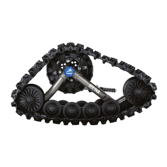
CAMSO ATV T4S Adjustments
Hide thumbs
Also See for ATV T4S:
- Installation manuallines (16 pages) ,
- Installation manuallines (20 pages) ,
- Owner's manual (35 pages)
Advertisement
Advertisement
Table of Contents

Subscribe to Our Youtube Channel
Summary of Contents for CAMSO ATV T4S
- Page 1 CAMSO ATV T4S FOR ALL-TERRAIN VEHICLES ATV T...
- Page 2 Incorrect adjustments can decrease the performance of the systems and result in premature wear or breakage of certain components. 1099-00-2231 - VERSION A are trademarks of Camso inc. ® All rights reserved. ©2019 Camso inc. Printed in Canada.
- Page 3 The serial number’s last digit (0, 1, 2, 3) indicates the mounting position on the vehicle. Lay out the track systems accordingly. Refer to Figure 1 and Figure 2. NOTE: If the serial numbers on the track systems do not match, contact your authorized Camso dealer / distributor.
- Page 4 ADJUSTMENTS ADJUSTMENTS NOTE: To make the following adjustments, position • Loosen jam nut (1). Adjust length of rod end (2) the vehicle on a flat and level surface. by rotating the steering limiter support plate on (3) the stabilizing arm. Use a 30 mm wrench to rotate support plate and obtain 254 mm above ANGLE OF ATTACK - FRONT SYSTEMS the ground.
- Page 5 ADJUSTMENTS NOTE: Once the angle of attack on the front systems is set, verify once again to confirm the adjustment. Figure 8 • Loosen nut (3) compressing stabilizing rod spring. See Figure 9. Figure 7 BASIC TUNING (Front Track Systems) •...
- Page 6 ADJUSTMENTS • Loosen anti-rotation bracket bolts (3) to allow the anti-rotation retainer (4) to rotate on its axis. See Figure 14. Figure 11 • IMPORTANT: Double-check minimum distance between nut and stabilizing Figure 14 arm guide. Re–adjust as needed. Figure 12. •...
- Page 7 ADJUSTMENTS • Re-tighten anti-rotation bracket bolts (3) to 50 N•m [37 lb-ft] of torque. See Figure 17. Figure 18 Dimension A: distance between inner front wheels Dimension B: distance between inner back wheels Figure 17 NOTE: Once the angle of attack on the rear systems Dimension A must be equal to or greater than is set, verify once again to confirm the dimension B without exceeding 3 mm [1/8 inch].
- Page 8 ADJUSTMENTS Measure A: Measure the distance inside the front Measure B: Measure the distance inside the rear Ø202 mm wheels on the front Track Systems. Ø202 mm wheels on the front Track Systems. See See figures 20, 21 and 22. figures 23, 24 and 25.
-
Page 9: Track Tension
ADJUSTMENTS TRACK TENSION NOTE: The track tension testing tool, shown below in Figure 28, can be purchased through an authorized Camso dealer. Part #2000-00-3125. WARNING The tensioner assembly bolt must never be loosened while adjusting the track tension. This bolt is designed for assembly and alignment of the tensioner with the frame. -
Page 10: Component Installation
CAMSO ATV T4S TRACK SYSTEMS INSTALLATION AND ADJUSTMENT CHECKLIST ** Steps in this checklist are laid out in logical order. They should be performed in succession to optimize the track system installation on the vehicle. ** 1 - COMPONENT INSTALLATION A - INSTALLATION OF REAR ANCHOR BRACKETS * Refer to INSTALLATION GUIDELINES section entitled "Rear track systems"...


Need help?
Do you have a question about the ATV T4S and is the answer not in the manual?
Questions and answers