Advertisement
Quick Links
R
IVER
D
EPLOYMENT
Information included herein is controlled by the Export Administration Regulations (EAR) and may
require an export license, license exception or other approval from the appropriate U.S. Government
agency before being exported from the United States or provided to any foreign person. Diversion
contrary to U.S. law is prohibited.
R
AY
G
UIDE
P/N 95B-6131-00 (April 2022)
© 2022 Teledyne RD Instruments, Inc. All rights reserved.
www.teledynemarine.com/rdi
Advertisement

Related Manuals for Teledyne RIVERRAY


Summary of Contents for Teledyne RIVERRAY
- Page 1 EPLOYMENT UIDE P/N 95B-6131-00 (April 2022) © 2022 Teledyne RD Instruments, Inc. All rights reserved. Information included herein is controlled by the Export Administration Regulations (EAR) and may www.teledynemarine.com/rdi require an export license, license exception or other approval from the appropriate U.S. Government agency before being exported from the United States or provided to any foreign person.
-
Page 2: Table Of Contents
(this can take up to 24 hours). Once you have secured an account, use the Teledyne Marine software portal to access this data with your unique username and password. -
Page 3: Preparing The Adcp
(registration code is required). 95B-6130-00 RiverRay Getting Started A printed reference card showing how to get started with the RiverRay. 95B-6131-00 RiverRay Deployment Guide A Printed guide showing the steps needs for a successful deployment. - Page 4 Both WinRiver II and TRDI Toolz programs are needed to test and de- ploy the RiverRay system. 3. Manuals are available for download on http://www.teledynemarine.com/rdi. Download the River- Ray Guide. PDF versions of all RiverRay documentation including this deployment guide are available for download. Quick Review...
-
Page 5: Connecting To The Adcp
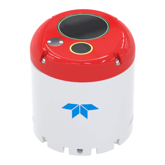
What type power does my system need? The RiverRay ADCP requires a DC supply between 10.5 volts to 18 volts. Either an external DC power sup- ply or battery can provide this power. The standard 12v 7 ah battery supplied with the Boat should power the ADCP for ~40 hours by itself, or ADCP + GPS for ~8 to 12 hours. - Page 6 LED should go out and the green LED will blink twice and then stay on. This indicates that the RiverRay self-test has passed. If the red LED stays on, wait a few minutes, cycle the power off, and back on and check the LEDs again.
- Page 7 14. To use the RiverPro’s vertical beam, check the Vertical Beam Profile Ping box. 15. On the Configuration Dialog, ensure the ADCP type matches the RiverRay and the indicator next to the RiverRay is green. Verify the blue LED on the RiverRay ADCP is on. Page 5...
- Page 8 LEDs light. After a few seconds, the red LED should go out and the green LED will blink twice and then stay on. This indicates that the RiverRay self-test has passed. If the red LED stays on, wait a few minutes, cycle the power off, and back on and check the LEDs again.
- Page 9 11. Click the Close button once more to exit the Peripherals Configuration Dialog. 12. Start a new measurement in WinRiver II. 13. On the Configuration Dialog, ensure the ADCP type matches the RiverRay and the indicator next to the RiverRay is green.
-
Page 10: Using Gps
Using GPS Integrated GPS The RiverRay ADCPs support integration of GPS data into the ADCP data stream. This approach mini- mizes the potential for latency in the GPS data and does not require a dedicated communications channel between the GPS receiver and the user’s computer. - Page 11 RiverRay Deployment Guide P/N 95B-6131-00 (April 2022) >sf9 If you do not know the GPS baud rate, type External NMEA baud detection enabled (9) (autodect). > >sf2 Type to view the data coming from the GPS; This is External NMEA diagnostics ON, pinging disabled an example of a working GPS that is outdoors providing fixes.
- Page 12 P/N 95B-6131-00 (April 2022) RiverRay Deployment Guide WinRiver II GPS Configuration Start WinRiver II. Using the Measurement Wizard, select the checkbox for Int. GPS and configure the baud rate to match that of the receiver. The baud rate must be greater than 9600. The recommended baud rate is 57600 or 115,200.
-
Page 13: Prepare For Discharge Measurement
E T T H E L O C K Prepare for Discharge Measurement The Hydrologist arrives at the site with a RiverRay and all of the ancillary equipment necessary to per- form a discharge measurement. • Tethered boat w/ tagline –... - Page 14 Run Built-In Tests The RiverRay is commanded to perform a BIT test on power up, and flashes its LED lights to indicate the results of the test. It simultaneously transmits the results of the BIT test, the status of the internal GPS connection and any ancillary devices connected to it to the host computer.
- Page 15 RiverRay Deployment Guide P/N 95B-6131-00 (April 2022) If the RiverRay was left in the hot sun, its temperature can quickly rise to 35⁰ C before use. When initially placed in the water, the thermal mass of the RiverRay housing near the temperature sensor initially affects the temperature measurement.
-
Page 16: Locating The Start & Stop Positions
Locating the Start and Stop Positions While the RiverRay is pinging, the Hydrologist positions the boat until the application shows that the Ri- verRay is reliably collecting at least two bins of data and marks the position on the tagline for future refer- ence. -
Page 17: Discharge Measurements
A proper moving boat discharge measurement consists of multiple transects – passes across the measure- ment location from one bank to the other, collecting data continuously as they cross. For each transect, the Hydrologist must maneuver the RiverRay to the marked position at one bank of the measurement lo- Locating the Start and Stop... - Page 18 P/N 95B-6131-00 (April 2022) RiverRay Deployment Guide Step by Step Data Collection 1. Open or create a measurement file. 2. Press F4 to start pinging. 3. At the start/stop position, press F5 to start the transect. 4. Enter the starting distance from the shore.
- Page 19 RiverRay Deployment Guide P/N 95B-6131-00 (April 2022) Data Collections Tips • Locate the point where a solid two-depth cell measurement can be measured on both banks. Stake or otherwise mark these locations. They represent the starting and stopping points for the tran- sects.
-
Page 20: Glossary Of Common Terms
P/N 95B-6131-00 (April 2022) RiverRay Deployment Guide Glossary of Common Terms Actors: • Field hydrologist/Technician • Data Analyst Expert (DAE ) Data Collection Terminology: • Left/Right Bank – The Left bank is defined as the bank that would be on your left side if you were looking downstream. -
Page 21: Conclusion
Quick reference card that shows snap shots of the serial communications screens during setup. SxSPro Software User’s Guide SxS Pro is a stationary ADCP discharge data collection and processing program for Teledyne RD Instru- ment’s (TRDI) Rio Grande, StreamPro, RiverRay, and RiverRay ADCP models. This program creates a measurement file, sends commands to the ADCP, lets the user collect data, visually displays the data, post-processes the data, and generates reports. - Page 22 P/N 95B-6131-00 (April 2022) RiverRay Deployment Guide OTES Page 20 EAR-Controlled Technology Subject to Restrictions Contained on the Cover Page.
Need help?
Do you have a question about the RIVERRAY and is the answer not in the manual?
Questions and answers