Table of Contents
Advertisement
Advertisement
Table of Contents

Related Manuals for Teledyne MB1


Summary of Contents for Teledyne MB1
- Page 1 HARDWARE MANUAL Version: 1.9 Teledyne Odom Hydrographic 1450 Seaboard Avenue Baton Rouge Louisiana 70810 United States of America Telephone: +1 (225) 769-3051 Fax: +1 (225) 766-5122 odom@teledyne.com www.odomhydrographic.com Number of pages: 37 Date: 14 Sep 13 ...
-
Page 2: Revision History
User Manual Revision History Version Date Author Remarks 17 May 12 M Redmayne 18 May 12 M Redmayne 21 May 12 M Redmayne 1. Addition of technical drawings 2. Addition of other mounting methods 3. Revision of RTA drawing 31 May 12 M Redmayne 1. -
Page 3: Table Of Contents
Real Time Appliance (RTA) .................... 6 Power/Data Cable ......................6 Mounting Plate ........................ 7 Digibar V (optional) ......................7 Power Supply ......................... 7 Possible Configurations of the MB1 ................7 COMPONENTS ........................9 Sounder .......................... 9 3.1.1 Optional Internal Motion Sensor ................10 3.1.2... - Page 4 Assembling the Optional Fairing ................... 23 4.6.1 Gather Required Tools and Parts ................24 4.6.2 Connect the Power/Data Cable and Digibar V Cable (if used) to the MB1 ... 24 4.6.3 Attach Rear Section ....................24 4.6.4 Attach Rear Top Section ..................25 4.6.5...
-
Page 5: Introduction
To make learning about the features of MB1 easy to follow, this document is structured as a step-by-step manual. The first manual (this manual) covers the MB1 as a product, it provides instructions on how to install the hardware, how cables are wired to their connectors and some simple troubleshooting tips. -
Page 6: Product Description
PRODUCT DESCRIPTION System Overview The MB1 consists of a multibeam sonar unit with an interface unit, called the Real Time Appliance (RTA). In order to be effectively used for hydrographic surveying, the user will require additional components for positioning, motion sensing, collection of data, determining sound velocity in the water as well as a computer to run the operating software. -
Page 7: Mounting Plate
CABLEPOWDC) by Odom when required. Possible Configurations of the MB1 The MB1 can be used as a standalone sonar as part of a pre existing suite of other sensors (Motion, Heading, Position etc.) or has configurable options. The options that may be added to the system are an internal GPS & Heading board (Hemisphere H320 model), TSS DMS525 motion sensor and the Digibar V real time sound velocity probe. - Page 8 User Manual GPS (Position) Heading Motion (HPR) Real Time SVP Internal External Internal External Internal External Internal External Single Head Dual Head * Note: At the time of writing the internal motion sensor cannot be rotated past 10 degrees of roll. External motion sensor will be required in this case.
-
Page 9: Components
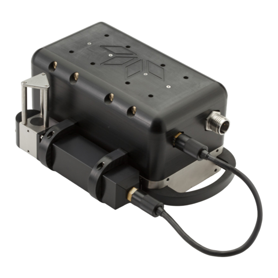
User Manual COMPONENTS Sounder The sounder consists of a Titanium lower portion, housing the acoustic transmit and receive arrays. The upper portion houses the internal electronics and is manufactured from Acetal, a tough and corrosion resistant plastic. The two connectors shown above are used for a connection to a real time sound velocity probe, the Odom Digibar V, and the other is a power/data interface for the unit. -
Page 10: Optional Internal Motion Sensor
Always ship the unit using the supplied shipping container. Real Time Appliance (RTA) The RTA is the center of the MB1 system. It serves as the connection box for all the sensors as well as providing better than 1 ms timing on all sensors including the sonar. -
Page 11: Front Panel
User Manual When setting up the MB1, the RTA should be placed on a non-insulating surface wherever possible to encourage heat to dissipate from the base plate. This is especially important in hot environments or where the unit is exposed to sunlight. Failure to sufficiently dissipate the heat may result in a safety hazard to personnel. -
Page 12: Rear Panel
User Manual Heading At rate of heading input, 5Hz Spare TSPU Various When communicating with TSPU Sonar 1 Data Various When communicating with Sonar Ping As per ping rate of sonar Depth and computer processor speed dependent Link Continuous When sonar is connected Sonar 2 Data Various... - Page 13 User Manual with the timing of the RTA when the BNC is used for the PPS signal. This will be seen as a timing error within the Image control software, along with the PPS LED blinking at rates other than once per second. If this occurs, pin 9 of the GPS I/O RS232 can be disabled in one of two ways: A null modem with pin 9 disabled can be used to interface between the GPS and the GPS I/O on the RTA.
- Page 14 User Manual (iii) Mounted to the rear panel is the interface board to the serial connectors. This has 4 small jumper connections, two of which will determine whether pin 9 and pin 8 can be used to accept the PPS signal. There are also two disconnected jumpers at the top of the board - do not change these.
- Page 15 User Manual 3.2.2.3 GPS I/O This RS232 connector is used to interface the positioning device into the RTA. The 3 messages to be used are NMEA ZDA, GGA and VTG at rates of 1-5 Hz. The formats of the standard NMEA sentences are as follows: $GPGGA,hhmmss.ss,llll.ll,a,yyyyy.yy,a,x,xx,x.x,x.x,M,x.x,M,x.x,xxxx*hh Header Time in UTC (hours, minutes, seconds and decimal seconds)
- Page 16 User Manual 3.2.2.4 Heading I/O This RS232 connector is used to input heading to the RTA. The accepted message is NMEA HDT at 5 $GPHDT,x.x,T,*hh Header Heading degrees, True Fixed 'T' means true heading Checksum 3.2.2.5 Spare I/O This port has been included for input from other devices, such as Acoustic Doppler Current Profilers (ADCPs).
- Page 17 3.2.2.12 TSPU PC This Ethernet connector interfaces with the computer that is to run the MB1 controller software. One end of the supplied Category 5e cable should be inserted into this connector, and the other end into the computer dedicated to operating the MB1 software.
- Page 18 GGA / ZDA / VTG Once these have been set, ensure to note the baud rates used and enter into the Image software as detailed in the MB1 software manual. 3.2.4 Configuring the RTA Hardware to Operate With Internal/External GPS The RTA has an internal dipswitch that allows the unit to be used in a variety of modes.
-
Page 19: Power/Data Cable
User Manual MB1 configuration options Internal GPS (GGA/ZDA) External GPS (GGA/ZDA) Internal Heading (HDT) External Heading (HDT) 1PPS Internal (from H320) 1PPS External (from BNC) 1PPS External (from GPS I/O pin 9) Dipswitch configurations - O = off, 1 = On, X = either off or on By default, the system will be configured to use the internal GPS, heading and PPS when an internal board is present. - Page 20 User Manual Caution: Do not pick up the sounder using the power/data cable At the dry end (RTA end) routinely inspect the connector and lightly lubricate with 3M lubricating spray or equivalent when necessary. Page 20 of 37 7/6/12 ...
-
Page 21: Installation
User Manual INSTALLATION Mounting the Sonar There are three main methods of mounting the sonar: Using M6X1.0 threaded holes in the top of the sonar housing Using M6X1.0 threaded holes on the sides of the base of the sonar housing Using an optional universal mounting plate Most commonly the unit is mounted over the side of the vessel, using a suitable pole and flange arrangement. -
Page 22: Mounting The Sonar Using Universal Mounting Plate (Optional)
Acceptable models can be identified by either black standoffs or an MB1 logo on the reflector. When purchased with the MB1, the Teledyne Odom Digibar V comes with mounting hardware to attach the unit to the side of the MB1 sonar head. -
Page 23: Connecting The Sensors
Assembling the Optional Fairing An optional semi rigid fairing is available for the MB1 multibeam system. The fairing performs two finctions. Primarily it is designed to reduce drag on the sonar when it is moving through the water. -
Page 24: Gather Required Tools And Parts
Attach Rear Section With the MB1 placed on it's end, slide the rear section onto the back of the MB1, with the grooved part in line with the bottom of the sonar. Thread the 4 long Hex bolts with a split ring and regular washer each. -
Page 25: Attach Rear Top Section
User Manual Rear Section Placed on MB1 (left) and bolted (right) 4.6.4 Attach Rear Top Section Next take the rear top section and thread the Power/Data cable through the cut out hole in the top. Thread the Digibar V cable (if used) through the small cable cutout on the side of the rear section to one side. -
Page 26: Attach Front Section
The front section is best attached with the unit sitting flat (transdcuer face down) on a table with the front of the unit pointing towards you. Take the front section and position it over the front of the MB1. Take the two long Hex bolts, thread each with a split and regular washer, then insert them into the uppermost two holes of the section. - Page 27 User Manual Front section attached Complete Fairin Page 27 of 37 7/6/12 ...
-
Page 28: Annex A - System Specifications
User Manual ANNEX A - SYSTEM SPECIFICATIONS Operating Frequency (kHz): 170 to 220 Range Resolution: 3.6cm Pulse Width: Selectable, 50-600 µs Analog to Digital Conversion: 24 bit Maximum ping rate: 60 Hz Number of bathymetric beams: 10 to 512 Maximum total swath width: 60 degrees from nadir, total 120 degrees Maximum sounding depth at nadir: 240m... -
Page 29: Annex B - Physical Dimensions
User Manual ANNEX B - PHYSICAL DIMENSIONS Page 29 of 37 07/16/13 ... - Page 30 User Manual Page 30 of 37 07/16/13 ...
- Page 31 User Manual Page 31 of 37 7/6/12 ...
- Page 32 User Manual Page 32 of 37 7/6/12 ...
- Page 33 User Manual GPS Antennas supplied with Optional Internal GPS - Courtesy NGS/NOAA Page 33 of 37 7/6/12 ...
-
Page 34: Annex C - Cable Connectors
User Manual ANNEX C - CABLE CONNECTORS Note: All connector views are as seen looking at the face of the cable connector on the rear of the RTA. Sonar 1 and 2 Letter Color Description Orange Orange/White Brown Brown/White Blue/White Blue Green Green/White... - Page 35 User Manual 1PPS (OPTIONAL) TELEDYNE TSS DMS CABLE Connection Core Pair RS422 RS232 DMS connector Color Pin # Power + Power 24V DC + Power 24V DC + Power - Power - Power - Primary Comms Ch B TxA primary...
-
Page 36: Annex D - Common Acronyms Used In This Manual
User Manual ANNEX D - COMMON ACRONYMS USED IN THIS MANUAL 1PPS One Pulse Per Second (same as PPS) Alternating Current Data format type for real time sound velocity Bayonet Neill-Concelman (type of connector) Direct Current dGPS Differential Global Positioning System NMEA position data string Global Positioning System Heave Pitch Roll (motion data) -
Page 37: Annex E - Spare Parts & Part Numbers
Fuse, 5 Amp for RTA Optional Power Supply 3015-0001-0000 Power Supply, Auto Switching 110/240 input and 24 VDC 150 Watt output Optional Digibar V 3012-0102-0000 Digibar V Sound Velocity probe for MB1 1900-0164-0000 Silicone Grease, 5gm tube 81G-6002 Clamp, Digibar V 81G-6003 Spacer, Digibar V M4MM.SPLIT.TI...
Need help?
Do you have a question about the MB1 and is the answer not in the manual?
Questions and answers