Table of Contents
Advertisement
Quick Links
Advertisement
Table of Contents

Related Manuals for Teledyne Echotrac MKIII


Summary of Contents for Teledyne Echotrac MKIII
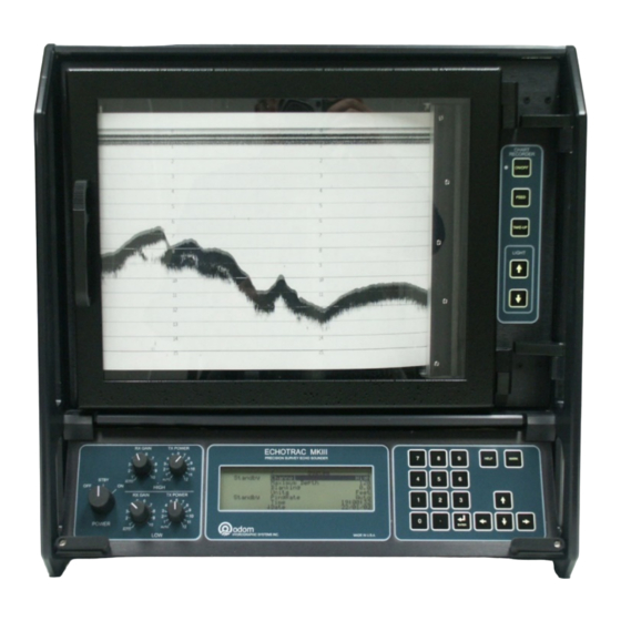
- Page 1 ECHOTRAC MKIII OPERATOR'S MANUAL Version: 4.06 Teledyne Odom Hydrographic Teledyne Marine Fabriksvangen 13 3550 Slangerup Denmark Telephone: +45 47 38 00 22 Fax: +45 47 38 00 66 www.teledynemarine.com/odom-hydrographic/ Number of pages: 48 Date: 21 January 2019...
- Page 2 S.F. Apsey Changes from Echotrac MKIII 3.05 to 3.06: 1-When the Echotrac MKIII is set to read in heave through com4 it will check to see if the first character in the string is an ‘R’ (remote heave). If the first character is an ‘R’ the Echotrac will use the remote heave value for corrections otherwise the Echotrac will use the local heave.
- Page 3 Updated support e-mail throughout document. Warning, Caution, and Note boxes added throughout document where relevant. 1.2 Echotrac MKIII Operator’s Manual – new section about the purpose, scope, warnings and notes, etc. 4, 5, and 7: Somewhat rearranged, reworded. App. A LCD15 Module. NEW.
-
Page 5: Table Of Contents
1.1.4 LCD Chart Panel ..........................7 1.1.5 Keypad ..............................7 1.1.6 Receivers .............................7 1.1.7 Transmitter ............................7 1.1.8 Communication Ports...........................8 Echotrac MKIII Operator’s Manual ......................8 1.2.1 Purpose..............................8 1.2.2 Scope ..............................8 1.2.3 Warnings, Cautions, and Notes ......................8 1.2.4 Glossary ...............................8 Installation................................9 Echotrac DF 3200 MKIII Recorder Installation ....................9 2.1.1... - Page 6 A.3.2 File Locations .............................45 A.3.3 Installing Programs ..........................45 Appendix B – AUX Modification for SILAS Output.....................46 Appendix C – Support and Service........................48 Support..............................48 Returning Goods for Service ........................48 Echotrac MKIII Operator's Manual 4.06 Page 6 of 48 January 21, 2019...
-
Page 7: Introduction
1 INTRODUCTION 1.1 Echotrac MKIII The Echotrac MKIII professional grade echo sounder Recorder, Digitizer, Transceiver, utilizes multiple processors including two dedicated Digital Signal Processors (DSPs), working in concert to accomplish specific analysis tasks while communicating effectively on a real-time basis in order to assure accurate measurements under difficult sea conditions and over all types of seabed. -
Page 8: Communication Ports
1.1.8 Communication Ports The Echotrac MKIII has 4 serial ports that can be configured to interface with computers, positioning systems, motion reference units and remote displays. The MKIII also has an Ethernet port that outputs the 16 bit samples of the acoustic data for further processing or visualization. -
Page 9: Installation
A 5-amp fuse is included in the AC input connector as well. Echotrac MKIII Operator's Manual 4.06 Page 9 of 48... -
Page 10: Chart Paper
General Paper Description The Echotrac MKIII uses either thermal film or high quality thermal paper as the recording media for the analog chart. The rolls are 216mm (8.5") wide and contain approximately 52m (170') of paper (film rolls are approximately 30m long). -
Page 11: Transducer Installation
The transducer should be mounted far enough aft of the bow so that bubbles generated by the bow wave will not pass over the face of the unit. Echotrac MKIII Operator's Manual 4.06 Page 11 of 48... -
Page 12: Through Hull" Installation
In all of the above installations, particular care should be taken to assure that the transducer radiating face remains as parallel to the water surface as possible while the vessel is underway. Echotrac MKIII Operator's Manual 4.06 Page 12 of 48... -
Page 13: Echotrac Mkiii Cable Connections
2.3.5 GPS In GPS In is only used when the Echotrac MKIII has a built in GPS unit. If the Echotrac MKIII has a built in GPS then this is the configuration port for the GPS or can be used to input external RTCM correction to the GPS. -
Page 14: Gps Out
2.3.6 GPS Out GPS Out is only used when the Echotrac MKIII has a built in GPS unit. If the Echotrac MKIII has a built in GPS then this is the output port for the GPS data. Connector PN Pin Number... -
Page 15: Tx1
2.3.10 TX1 TX1 is the main transducer connection port for the Echotrac MKIII. If using Odom Hydrographic Systems, Inc. normal dual frequency transducer or a signal frequency transducer connect the transducer here. Connector PN Pin Number Signal Description MS3116J14-5P Shield... -
Page 16: Quick Start Operating Procedures
3 QUICK START OPERATING PROCEDURES The Echotrac MKIII is designed to operate with minimal operator input, yet still provide the flexibility required by a wide range of survey conditions. With the unit’s power switch in the OFF position, confirm that the Power (either AC or 24VDC), Transducer and Computer cables are properly connected at the rear of the unit. -
Page 17: Chart Recorder Controls
4.4 LIGHT The UP and DOWN arrows should be pressed to either increase or decrease the brightness of the Chart Illumination LEDs. Echotrac MKIII Operator's Manual 4.06 Page 17 of 48 January 21, 2019... -
Page 18: Display Panel Controls
5 DISPLAY PANEL CONTROLS Figure 4: MKIII Display Panel The Echotrac MKIII provides the operator with complete access to all system parameters and variables via front panel mounted controls. These controls are divided into two major groups: Conventional ANALOG controls (knobs) ... -
Page 19: Transmitter And Receiver Controls
Fix Mark on the chart as well. Annotation of the Fix Mark is controlled by the Annotation parameter. The Mark button can also be used to reset the Echotrac MKIII in case the user cannot select the reset parameter from the System Menu. -
Page 20: Parameter Entry System
The default value for Blanking is “0” while the value can be increased to the Maximum Depth value. Echotrac MKIII Operator's Manual 4.06 Page 20 of 48... - Page 21 Although every effort has been expended to guarantee seamless data flow among the processors in the MKIII, as in any multi-processor environment the possibility exists for one to lose “Sync” and cause the sounder to “act differently”. Echotrac MKIII Operator's Manual 4.06 Page 21 of 48...
-
Page 22: Setup Menu
3 ms 3 ms The maximum usable pulse width is limited by total available capacity and depends on the operational environment. It is typically capped at approximately 3 ms. Echotrac MKIII Operator's Manual 4.06 Page 22 of 48 January 21, 2019... - Page 23 When set to none the digitizer will detect the signal with the highest energy. Use this setting in very deep depth conditions. Echotrac MKIII Operator's Manual 4.06 Page 23 of 48...
- Page 24 The value entered is in meters or feet depending on the units used. 5.2.2.12 Pre Amp Gain This parameter controls the gain to an optional signal interface card in the Echotrac MKIII. This gain does not affect the normal MKIII receiver.
-
Page 25: Calibrate Menu
Once the “k” value is determined, it will not change until the sounder or the transducer is changed. The Index parameter should be adjusted to make the measured draft and the calculated draft equal. Echotrac MKIII Operator's Manual 4.06 Page 25 of 48... -
Page 26: Chart Menu
End of Chart is used to compute the echo travel time and thereby sets the auto ping rate of the unit. Echotrac MKIII Operator's Manual 4.06 Page 26 of 48... - Page 27 Deso firmware version. This parameter only affects the grid lines when the Units are set to Meters. Echotrac MKIII Operator's Manual 4.06 Page 27 of 48...
-
Page 28: Communications Menu
DESO25 or NMEA) from Com 1, by the amount of the input heave value. Only the designated Heave string outputs the actual value of the heave correction and does not “correct” the depth output for that heave value. Echotrac MKIII Operator's Manual 4.06 Page 28 of 48 January 21, 2019... -
Page 29: Diagnostic Menu
MKIII to data acquisition systems or during training of new operators. It enables many of the features of the system to be demonstrated without ever leaving the office. Echotrac MKIII Operator's Manual 4.06 Page 29 of 48 January 21, 2019... - Page 30 Flash RAM. Front Panel, Printer, and Communications Processors should all agree in their version numbers. The two DSP Processors should also agree in their versions, but their version number will not necessarily agree with that of the other three processors. Echotrac MKIII Operator's Manual 4.06 Page 30 of 48 January 21, 2019...
-
Page 31: Operating Procedures
6 OPERATING PROCEDURES The following sequences are typical operating procedures for Echotrac MKIII. The procedures may vary according to survey requirements and are intended only as a guide. It is assumed that the operator is familiar with the various controls and their associated functions as detailed in the preceding sections of this manual. -
Page 32: Calibration
9. Repeat the DRAFT calibration (steps 2 through 6) for the Low frequency (Draft Lo and Index Lo). Calibration should not be attempted in DUAL mode. Echotrac MKIII Operator's Manual 4.06 Page 32 of 48 January 21, 2019... -
Page 33: Data I/O
The characters of 2 & 3 are in upper case, when the units are in tenths of feet, and in lower case, when the units are in centimeters. Example: <sp>ETOL<sp>DDDDDCR Echotrac MKIII Operator's Manual 4.06 Page 33 of 48 January 21, 2019... - Page 34 The characters of 2 & 3 are in upper case, when the units are in tenths of feet, and in lower case, when the units are in centimeters. Example: <sp>etEH<sp>DDDDD+HHHHCR Echotrac MKIII Operator's Manual 4.06 Page 34 of 48 January 21, 2019...
- Page 35 <sp>, f Space or “f” indicating feet units m, t “m” indicates meters, “t” indicates feet Carriage Return Line Feed Example: DB12345.69<SP>m<CR><LF>; Lo, 12345.69 meters *<CR><LF> ; Terminator symbol Echotrac MKIII Operator's Manual 4.06 Page 35 of 48 January 21, 2019...
-
Page 36: Deso Ddv
“m/s” indicates meters per second Carriage Return Line Feed Example: DA12345.69<SP>m<CR><LF> ; Hi, 12345.69 meters DG<SP>0.00<SP>m<SP><CR><LF> ; Draft 0.00 meters CS1500<SP>m/s<CR><LF> ; Sound Velocity 1500 meters per second *<CR><LF> ; Terminator symbol Echotrac MKIII Operator's Manual 4.06 Page 36 of 48 January 21, 2019... -
Page 37: Deso Commands
HEX 20 ("space"). Care should also be taken to avoid annotation overrun, which is caused by grouping annotated events so closely together that they obscure the record. Echotrac MKIII Operator's Manual 4.06 Page 37 of 48 January 21, 2019... -
Page 38: External Serial Control Of Echotrac Parameters
SPACE This character will be represented by “_” in the examples below. Data Link Escape The letter “n” represents each single digit of the New Value. (also known as Control-P) Minimum is 1 digit. Maximum is 8 digits. Echotrac MKIII Operator's Manual 4.06 Page 38 of 48 January 21, 2019... - Page 39 Also, as of version 3.06 the ID used to request a parameter value changed from 86 to 187. See chapter 8 Overview parameters and settings for a table listing all the parameters and their unique identifier. Echotrac MKIII Operator's Manual 4.06 Page 39 of 48 January 21, 2019...
-
Page 40: Overview Parameters And Settings
8.3 Serial Ports – Serial 3 Serial port 3 is dedicated to connecting a GPS to the Echotrac MKIII. The MKIII accepts NMEA GLL or GGA sentences. It is recommended to set the GPS to output only one of these strings, as too much data can interfere with the processor’s other tasks. -
Page 41: Uploading Firmware
Do not interrupt the process. If the upgrading procedure fails and the Echotrac MKIII fails to display a version number for one of the modules after cycling the power, the flash chips in that module must be replaced with a working set of flash chips. - Page 42 DSP is connected to com2 of the computer. When prompted with a file name type in MK3Digi.hex, the program should then upgrade the firmware on the DSP. 11. Switch the Echotrac MKIII to Off and move the shunt from JP10 to the two left most pins. 12. Repeat steps 6-11 for the other DSP.
-
Page 43: Appendix A - Lcd15 Module
The LCD15 module has a fully functional computer inside that can run most standard Windows programs. Installed on the LCD15 is Teledyne Odom Hydrographic eChart Control/Display software version 1.4.0. This software allows the operator to control, display and log data from the MKIIIE. The files are logged as .DSO files that can be played back using the control software. -
Page 44: Mouse And Keyboard Considerations
A cover serving as an air-exhaust port is located on the upper right side of the sounder. This area should not be blocked during operation. Echotrac MKIII Operator's Manual 4.06 Page 44 of 48 January 21, 2019... -
Page 45: Making Changes To The Embedded Software Configuration
Make sure that the MKIIIE is operated with the front control panel extended to allow for proper airflow through the sounder unit. Echotrac MKIII Operator's Manual 4.06 Page 45 of 48 January 21, 2019... -
Page 46: Appendix B - Aux Modification For Silas Output
3. Disconnect the AUX connector from connector J4. 4. Remove the lid covering the transmitter board and locate the low-frequency transmitter board (the one with the biggest transformer). 5. Locate J2 AUX-OUT. Echotrac MKIII Operator's Manual 4.06 Page 46 of 48 January 21, 2019... - Page 47 Do not connect both connectors from the AUX connector at the same time, as this will burn off the COM board. 8. Assemble the system, and the Silas output is ready. Echotrac MKIII Operator's Manual 4.06 Page 47 of 48 January 21, 2019...
-
Page 48: Appendix C - Support And Service
No goods may be returned without prior authorization, as evidenced by a Return Authorization (RMA) Number. Before returning any equipment for service, you must follow the Teledyne RESON equipment return procedure stated below. a) Contact a Teledyne RESON office to obtain an approved Return Material Authorization (RMA) number.
Need help?
Do you have a question about the Echotrac MKIII and is the answer not in the manual?
Questions and answers