Bodet Profil 750 Installation And Operation Manual
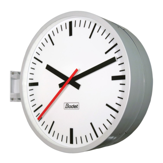
Analogue clocks
Hide thumbs
Also See for Profil 750:
- Quick start manual (12 pages) ,
- Installation and operation manual (49 pages) ,
- Installation and operation manual (31 pages)
Table of Contents
Advertisement
Available languages
Available languages
Quick Links
Profil 750 - Profil 760 - Profil 780
IMPULSION/ IMPULSE
AFNOR
RADIO
Manuel d'installation et de mise en service
Installation and operation manual
www.bodet-time.com
S'assurer à réception que le produit n'a pas été endommagé durant le transport pour réserve au transporteur.
When receiving goods please check nothing is broken otherwise make a claim near shipping company.
HORLOGES ANALOGIQUES
ANALOGUE CLOCKS
BODET Time & Sport
1 rue du Général de Gaulle
49340 TREMENTINES I France
Tel. support France: 02.41.71.72.99
Tel. support export: +33 241 71 72 33
1
Advertisement
Table of Contents

Related Manuals for Bodet Profil 750


Summary of Contents for Bodet Profil 750
- Page 1 HORLOGES ANALOGIQUES ANALOGUE CLOCKS Profil 750 - Profil 760 - Profil 780 IMPULSION/ IMPULSE AFNOR RADIO Manuel d’installation et de mise en service Installation and operation manual BODET Time & Sport 1 rue du Général de Gaulle 49340 TREMENTINES I France Tel.
-
Page 2: Table Of Contents
Table des matières INFORMATIONS RELATIVES À LA SÉCURITÉ 1. VÉRIFICATION INITIALE 1.1 Déballage de l’horloge 1.2 Nettoyage 1.3 Consignes de sécurité - précautions à l'installation 1.3.1 Utilisation de la notice 1.3.2 Sécurité - Installation électrique 1.3.3 Sécurité - Installation mécanique 1.3.4 Sécurité... - Page 3 Table of contents SAFETY INFORMATION 1. INITIAL CHECKS 1.1 Unpacking the clock 1.2 Cleaning 1.3 Safety instructions - Precautions for installation 1.3.1 Use of the instructions 1.3.2 Safety - Electrical installation 1.3.3 Safety - Mechanical installation 1.3.4 Safety - Opening the clock 2.
-
Page 4: Informations Relatives À La Sécurité
INFORMATIONS RELATIVES À LA SÉCURITÉ Les pictogrammes ci-dessous permettent d’illustrer des risques ou des sources de danger lors de l’installation, de l’utilisation et de la maintenance de ce produit. Symbole Description IEC60417 - 1641 Manuel d’utilisation IEC60417 - 5002 Positionnement de la pile IEC60417 - 5019 Connexion de terre de protection IEC60417 - 5032... -
Page 5: Vérification Initiale
1. VÉRIFICATION INITIALE Nous vous remercions d’avoir choisi une horloge Bodet. Ce produit a été conçu avec soin pour votre satisfaction selon les règles de notre système qualité ISO9001 et ISO14001. Nous vous recommandons de lire attentivement ce manuel avant l'installation du produit. -
Page 6: Sécurité - Installation Électrique
- Pour les horloges double face, chacune des 4 vis M8 doit être capable de supporter une traction de : 270 kg (pour une Profil 780) ou 150 kg (pour une Profil 750 ou 760). 1.3.4 Sécurité - Ouverture de l'horloge L’intérieur de cet équipement ne possède pas de pièces réparables par l’utilisateur : contacter... -
Page 7: Installation
2. INSTALLATION 2.1 Horloge simple face 2.1.1 Installation mécanique 2.1.1.1 Fixation murale Pour installer l’horloge sur le mur, celle-ci doit impérativement être ouverte préalablement. Suivez les étapes suivantes pour procéder à l'installation mécanique de l'horloge. Dévisser et retirer la vis d'entrée d'air située sous l’horloge pour laisser l’air rentrer. -
Page 8: Fixation Sur Potence (Option)
Une fois l'horloge câblée, nettoyer le joint puis appliquer de l'huile silicone dessus. Rapprocher la face avant de l’horloge puis reconnecter le câble de synchronisation allant du bornier (ou le câble plat partant de la carte électronique) vers le mouvement situé... - Page 9 La dépose d’un joint en silicone est recommandée entre la platine et le mur M8x65 pour assurer une étanchéité correcte. Positionner l'horloge sur la potence en démarrant par le premier point de fixation en haut avec une tige filetée et 2 écrous. Poursuivre l'attache de l'horloge à...
-
Page 10: Installation Électrique
2.1.2 Installation électrique Il existe différentes versions d’horloge : IMPULSION MIN 24V, MIN 1V5, AFNOR ou RADIO. Consulter l’étiquette du produit pour déterminer votre version. L’alimentation de l’éclairage (si option choisie) est toujours assurée via une alimentation reliée au secteur. 2.1.2.1 Modèles IMPULSION MIN 24V - MIN 1V5 Passer câble... -
Page 11: Modèle Radiosynchronisé
2.1.2.3 Modèle RADIOSYNCHRONISÉ Passer un câble secteur par le presse RADIO étoupe de droite puis connecter ce câble sur le bornier dans les bornes L-N- dédiées à la carte électronique (sigle ). Si l'horloge dispose de l'option éclairage, les 2 câbles secteur doivent provenir d'un même bâtiment. -
Page 12: Horloge Double Face
2.2 Horloge double face 2.2.1 Installation mécanique Ce type d’horloge dans sa version double face peut peser jusqu’à 28 Kg. A cela il faut ajouter les contraintes mécaniques lors du verrouillage, c’est pourquoi nous recommandons d’installer cette horloge double face de préférence sur un mur béton. Pour installer l’horloge double face, celle-ci doit impérativement être ouverte préalablement. -
Page 13: Fixation Avec Platine D'étanchéité Ip65 (Option)
Reconnecter le câble allant vers le mouvement sur cette face (limiter sa longueur avec l'embase). Avant de repositionner la face de l'horloge du côté à l'oeillet, procéder au câblage interne de l'horloge. Reportez-vous aux chapitres suivants de cette notice en fonction de votre modèle. En cas de maintenance ultérieure, retirez uniquement la face du coté... - Page 14 Retirer le calage en carton entre le mouvement et le cadran. À l’endroit où l’horloge doit être installée : percer 4 trous suivant la disposition et les cotes dimensionnelles indiquées ci-après pour la fixation de la potence. Insérer les tiges filetées (scellement chimique) dans les perçages.
- Page 15 Limiter la longueur de câble en le passant (mm) P750 P760 P780 dans l'embase câble afin d'éviter un phénomène d'ombrage en cas d'option éclairage (contact du câble avec le cadran une fois l'horloge fermée). Refermer l'horloge en replaçant la face démontée dans sa position originale.
-
Page 16: Installation Électrique
2.2.2 Installation électrique Il existe différentes versions d’horloge : IMPULSION MIN 24V, MIN 1V5, AFNOR ou RADIO. Consulter l’étiquette du produit pour déterminer votre version. L’alimentation de l’éclairage (si option choisie) est toujours assurée via une alimentation reliée au secteur. 2.2.2.1 Modèles IMPULSION MIN 24V - MIN 1V5 Passer câble... -
Page 17: Modèle Radiosynchronisé
2.2.2.3 Modèle RADIOSYNCHRONISÉ Passer un câble secteur par le bras de la potence puis connecter ce câble sur le bornier dans les RADIO bornes L-N- dédiées à la carte électronique (sigle ). Si l'horloge dispose de l'option éclairage, les 2 câbles secteur doivent provenir d'un même bâtiment. -
Page 18: Mise En Service Et Mise À L'heure 3.1 Réceptrice Impulsion Min 24V
3. MISE EN SERVICE ET MISE À L’HEURE 3.1 Réceptrice IMPULSION MIN 24V Un réseau de distribution horaire n’émet que des impulsions. Il est nécessaire d’arrêter le réseau et de mettre toutes les horloges réceptrices à la même heure avant le démarrage. Pour mettre à... -
Page 19: Caractéristiques Techniques
Informations complémentaires Pour modèle simple face: Ø câbles secteur : 5-10 mm (PG11) Ø câbles synchronisation : 4-8 mm (PG9) 4.2 Dimensions Profil 750 Simple Face 25,4 124,5 Profil 750 Double Face A ( 1 : 2 ) 11... - Page 20 Profil 760 Simple Face Profil 760 Double Face A ( 1 : 4 ) 11 Profil 780 Simple Face Profil 780 Double Face...
-
Page 21: Que Faire Si
5. QUE FAIRE SI..? VÉRIFIER. Que faire si... ? Vérifier Vérifier que le type de signal émis par l’horloge mère (Impulsion Minute 24V, AFNOR/ Irig-B), Pas de synchronisation après l’installation. est de même type que celui du mouvement l’horloge. Absence de message horaire depuis plus d’une Réceptrice AFNOR / Irig-B arrêtée heure. -
Page 22: Safety Information
SAFETY INFORMATION The following icons are used to indicate risks or sources of danger when installing, using and maintaining this product. Symbol Description IEC60417 - 1641 Operating instructions IEC60417 - 5002 Positioning of cell IEC60417 - 5019 Protective earth (ground) IEC60417 - 5032 Alternating current IEC60417 - 6041... -
Page 23: Initial Checks
AFNOR / RADIO: a slave clock driven by a master clock sending AFNOR NFS-87500A time code messages or by a GPS or radio receiving antenna. Depending on the clock model (Profil 750, 760 or 780) the position of the components inside the clock may change. -
Page 24: Safety - Electrical Installation
30 kg, - For double-sided clocks, each of the four M8 screws must be able to withstand a pull of: 270 kg (Profil 780), or 150 kg (Profil 750 or 760). 1.3.4 Safety - Opening the clock There are no user-serviceable parts inside this equipment. -
Page 25: Installation
2. INSTALLATION 2.1 Single-sided clock 2.1.1 Mechanical installation 2.1.1.1 Wall mounting The clock must be previously opened before being mounted onto the wall. Follow the steps below to proceed with the mechanical installation of the clock. Unscrew and remove the air inlet screw beneath the clock to let air in. -
Page 26: Mounting On Bracket (Optional)
Once the clock has been wired, clean the seal and apply silicone oil on it. Realign the front face of the clock and reconnect the synchronisation cable from the terminal block (or the flat cable from the electronic card) to the movement on the front face. - Page 27 It is recommended to apply a silicone seal between the plate and the wall for ensuring M8x65 correct watertightness. Place the clock on the bracket starting with the first fixing point at the top with a threaded rod and 2 nuts. Continue fixing the clock to the bracket by placing 2 fixing screws at the bottom of the bracket.
-
Page 28: Electrical Installation
2.1.2 Electrical installation There are different clock versions: IMPULSE MIN 24V, MIN 1V5 , AFNOR or RADIO. Refer to the product label to determine which version you have. The lighting (if option chosen) is always powered via a mains power supply. 2.1.2.1 IMPULSE MIN 24V - MIN 1V5 model synchronisation cable... -
Page 29: Radio-Synchronised Model
2.1.2.3 RADIO-SYNCHRONISED model Run a mains cable through the right- RADIO hand cable gland then connect this cable to the terminal block in the L-N- terminals dedicated to the electronic card (icon ) If the clock has the lighting option, the 2 mains cables must come from the same building. -
Page 30: Double-Sided Clock
2.2 Double-sided clock 2.2.1 Mechanical installation This double-sided clock can weigh up to 28 kg. It is important to take into account the mechanical stresses involved in locking, which is why we recommend installing this double-sided clock preferably on a concrete wall. The double-sided clock must be previously opened before being installed. -
Page 31: Mounting With Ip65 Sealing Plate (Optional)
Reconnect the cable to the movement on this clock face (limit its length with the cable clip). Before replacing the clock’s face on the grommet side, proceed with the clock’s internal cabling. Refer to the following chapters of this manual according to your model. - Page 32 Remove the cardboard wedge between the movement and the dial. Where the clock is to be installed: drill 4 holes according to the layout and dimensions indicated below for fixing the bracket. Insert the threaded rods (chemical seal) into the drilled holes. It is also possible to use anchor bolts.
- Page 33 Limit the length of the cable by running (mm) P750 P760 P780 it through the cable clip in order to avoid shading in the case of the lighting option (contact of the cable with the dial once the clock is closed). Close the clock by replacing the disassembled face back in its original position.
-
Page 34: Electrical Installation
2.2.2 Electrical installation There are different clock versions: IMPULSE MIN 24V, MIN 1V5 , AFNOR or RADIO. Refer to the product label to determine which version you have. The lighting (if option chosen) is always powered via a mains power supply. 2.2.2.1 IMPULSE MIN 24V - MIN 1V5 model Run the synchronisation cable through the bracket arm, then connect this... -
Page 35: Radio-Synchronised Model
2.2.2.3 RADIO-SYNCHRONISED model Run a mains cable through the bracket arm, then connect this cable to the terminal block in the RADIO L-N- terminals dedicated to the electronic card (icon ) If the clock has the lighting option, the 2 mains cables must come from the same building. -
Page 36: Starting The Clock And Setting The Time
3. STARTING THE CLOCK AND SETTING THE TIME 3.1 IMPULSE MIN 24V slave clock A time distribution network only emits impulses. It is necessary to stop the network and set all slave clocks to the same time before starting up. To set the time on the clock, adjust the thumb wheel located on the movement at the back of the removable clock face. -
Page 37: Technical Features
- EMC Directive 2014/30/EU - LVD Directive 2014/35/EU Additional information For single-sided models: Ø mains cables: 5-10mm (PG11) Ø synchronisation cables: 4-8mm (PG9) 4.2 Dimensions Profil 750 Single-sided 25,4 124,5 Profil 750 Double-sided A ( 1 : 2 ) 11... - Page 38 Profil 760 Single-sided Profil 760 Double-sided A ( 1 : 4 ) 11 Profil 780 Single-sided Profil 780 Double-sided...
-
Page 39: What To Do If
5. WHAT TO DO IF… CHECK. What to do if… ? Check Check that the signal type emitted by the master clock (Impulse Minute 24V, AFNOR/ No synchronisation after installation. IRIG-B) is the same signal type as the clock’s movement. No time message for over an hour. - Page 40 © 2023 BODET. All rights reserved. Tous droits réservés.
Need help?
Do you have a question about the Profil 750 and is the answer not in the manual?
Questions and answers