Sungrow SG110CX User Manual
Pv grid-connected inverter
Hide thumbs
Also See for SG110CX:
- User manual (118 pages) ,
- Quick installation manual (12 pages) ,
- Quick manual (21 pages)

Related Manuals for Sungrow SG110CX


Summary of Contents for Sungrow SG110CX
- Page 1 User Manual PV Grid-Connected Inverter SG110CX / SG110CX-20 / SG110CX-NI SG110CX_SG110CX–20_SG110CX–NI–UEN-Ver23-202307...
-
Page 3: All Rights Reserved
Software Licenses • It is prohibited to use data contained in firmware or software developed by SUNGROW, in part or in full, for commercial purposes by any means. • It is prohibited to perform reverse engineering, cracking, or any other operations that com... -
Page 4: About This Manual
Please read this manual carefully before using the product and keep it properly at a place for easy access. All contents, pictures, marks, and symbols in this manual are owned by SUNGROW. No part of this document may be reprinted by the non-internal staff of SUNGROW without written au... - Page 5 Symbols This manual contains important safety instructions, which are highlighted with the following symbols, to ensure personal and property safety during usage, or to help optimize the product performance in an efficient way. Please carefully understand the meaning of these warning symbols to better use the manual. DANGER Indicates high-risk potential hazards that, if not avoided, may lead to death or serious injury.
-
Page 6: Table Of Contents
Contents All Rights Reserved......................I About This Manual......................II 1 Safety Instructions ....................1 1.1 Unpacking and Inspection..................2 1.2 Installation Safety....................2 1.3 Electrical Connection Safety.................3 1.4 Operation Safety....................4 1.5 Maintenance Safety....................5 1.6 Disposal Safety.....................6 2 Product Description .................... - Page 7 4.3 Installation Tools....................22 4.4 Moving the Inverter.....................24 4.4.1 Manual Transport..................24 4.4.2 Hoisting Transport..................25 4.5 Installing Mounting-bracket.................26 4.5.1 PV Bracket-Mounted Installation.............. 27 4.5.2 Wall-Mounted Installation................. 28 4.6 Installing the Inverter..................29 5 Electrical Connection ..................31 5.1 Safety Instructions....................31 5.2 Terminal Description...................33 5.3 Electrical Connection Overview................35 5.4 Crimp OT/DT terminal..................
- Page 8 5.10.2 Wiring Procedure..................67 5.11 DRM Connection(For Countries “AU” and “NZ”)..........67 5.11.1 DRM Function..................67 5.11.2 Connection Procedure................68 5.12 Closing the Wiring Compartment..............69 5.13 Communication Module Connection (optional)..........70 6 Commissioning ..................... 72 6.1 Inspection Before Commissioning..............72 6.2 Commissioning Procedure..................72 7 iSolarCloud App ....................
- Page 9 9.2.1 Maintenance Notices................108 9.2.2 Routine Maintenance................109 9.2.3 Cleaning Air Inlet and Outlet..............110 9.2.4 Fan Maintenance..................110 10 Appendix ......................113 10.1 Technical Data....................113 10.2 Wring Distance of DI Dry Contact..............118 10.3 Quality Assurance...................119 10.4 Declaration of Conformity................120 10.5 Contact Information..................120...
-
Page 10: Safety Instructions
Perform operations considering actual onsite conditions. • SUNGROW shall not be held liable for any damage caused by violation of gen eral safety operation requirements, general safety standards, or any safety in struction in this manual. -
Page 11: Unpacking And Inspection
If there are problems with the above inspection items, do not install the device and contact your distributor first. If the problem persists, contact SUNGROW in time. 1.2 Installation Safety DANGER •... -
Page 12: Electrical Connection Safety
User Manual 1 Safety Instructions 1.3 Electrical Connection Safety DANGER • Before electrical connections, please make sure that the inverter is not damaged, otherwise it may cause danger! • Before electrical connections, please make sure that the inverter switch and all switches connected to the inverter are set to "OFF", otherwise electric shock may occur! DANGER... -
Page 13: Operation Safety
1 Safety Instructions User Manual WARNING • Check the positive and negative polarity of the PV strings, and connect the PV connectors to corresponding terminals only after ensuring polarity correctness. • During the installation and operation of the inverter, please ensure that the positive or negative poles of PV strings do not short-circuit to the ground. -
Page 14: Maintenance Safety
To avoid the risk of electric shock, do not perform any other maintenance operations beyond those described in this manual. If necessary, contact your distributor first. If the problem persists, contact SUNGROW. Otherwise, the losses caused is not cov ered by the warranty. -
Page 15: Disposal Safety
1 Safety Instructions User Manual NOTICE • If the paint on the inverter enclosure falls or rusts, repair it in time. Otherwise, the inverter performance may be affected. • Do not use cleaning agents to clean the inverter. Otherwise, the inverter may be damaged, and the loss caused is not covered by the warranty. -
Page 16: Product Description
Note Monocrystalline silicon, polycrystalline silicon and thin-film with PV strings out grounding. Inverter SG110CX, SG110CX-20, SG110CX-NI. Grid connection Includes devices such as AC circuit breaker, SPD, metering de cabinet vice. Boost the low voltage from the inverter to grid-compatible medi... -
Page 17: Product Introduction
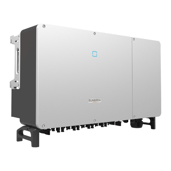
TN-C, TN-S, TN-C-S, TT, IT. The following figure shows the common grid configurations. NOTICE In a TT power grid, the N-PE voltage should be lower than 30 V. 2.2 Product Introduction Model Description The model description is as follows(Take SG110CX-20 as an example):... - Page 18 User Manual 2 Product Description Appearance The following figure shows the appearance of the inverter. The image shown here is for refer ence only. The actual product received may differ. figure 2-2 Inverter Appearance * The image shown here is for reference only. The actual product received may differ. Name Description LED indicator pan...
-
Page 19: Symbols On Product
2 Product Description User Manual figure 2-3 Product Dimensions(in mm) * The image shown here is for reference only. The actual product received may differ. 2.3 Symbols on Product Symbol Explanation Do not dispose of the inverter together with household waste. TÜV mark of conformity. -
Page 20: Led Indicator
The DC switch is used to disconnect the DC current safely whenever necessary. The SG110CX-NI is not equipped with DC switch. The SG110CX/SG110CX-20 is equipped with three DC switches, and each DC switch controls its corresponding DC terminals. Turn the DC switches to the ON position before restarting the inverter. -
Page 21: Circuit Diagram
2 Product Description User Manual 2.6 Circuit Diagram The following figure shows the main circuit of the inverter. figure 2-4 Circuit Diagram • The DC SPD provides a discharge circuit for the DC side overvoltage to prevent it from damaging the internal circuits of the inverter. - Page 22 User Manual 2 Product Description Parameter Configuration The inverter provides various settable parameters. Users can set parameters via the App to meet the requirements and optimize the performance. Communication Interface The inverter is designed with standard RS485 communication interfaces. The standard RS485 communication interfaces are used to establish communication connec tion with monitoring devices and upload monitoring data by using communication cables.
- Page 23 2 Product Description User Manual NOTICE • Before enabling the PID recovery function, make sure the voltage polarity of the PV modules to ground meets requirement. If there are any questions, contact the PV module manufacturer or read the corresponding user manual. •...
-
Page 24: Unpacking And Storage
• Check the scope of delivery for completeness according to the packing list. • Check the inner contents for damage after unpacking. Contact SUNGROW or the transport company in case of any damage or incompleteness, and provide photos to facilitate services. -
Page 25: Scope Of Delivery
3 Unpacking and Storage User Manual 3.2 Scope of Delivery 图 1: Scope of Delivery a. The mounting-bracket includes 2 mounting-bracket components and 1 connecting bar. b. The screws include two M4×10, two M6×65, and two M6×14 hex socket screws. c. - Page 26 User Manual 3 Unpacking and Storage • Store the inverter in the original packing case with the desiccant inside. • The storage temperature must be always between -40℃ and +70℃, and the storage rel ative humidity must be always between 0 and 95 %, non-condensing. •...
-
Page 27: Mechanical Mounting
4 Mechanical Mounting WARNING Respect all local standards and requirements during mechanical installation. 4.1 Safety During Mounting DANGER Make sure there is no electrical connection before installation. Before drilling, avoid the water and electricity wiring in the wall. WARNING Poor installation environment will affect system performance! •... -
Page 28: Location Requirements
• The ambient temperature and relative humidity must meet the following requirements. • Please consult SUNGROW before installing inverters outdoors in areas prone to salt dam age, which mainly are coastal areas within 500 meters of the coast. The deposition of salt... -
Page 29: Carrier Requirements
4 Mechanical Mounting User Manual fog varies largely with nearby seawater characteristics, sea wind, precipitation, relative hu midity, terrain, and forest coverage. • Install the inverter in a sheltered area to avoid direct sunlight and bad weather (e.g. snow, rain, lightning, etc.). The inverter will derate in high temperature environments for protec tion. -
Page 30: Clearance Requirements
User Manual 4 Mechanical Mounting In case the installation site is a level surface, mount the inverter to the bracket to meet the mounting angle requirements, as shown in the figure below. Take the following items into account when designing the bracket scheme: •... -
Page 31: Installation Tools
In case of multiple inverters, reserve specific clearance between the inverters. For other instal lation scenarios, please refer to the relevant technical documents on http://support.sungrow power.com/. In case of back-to-back installation, reserve specific clearance between the two inverters. - Page 32 User Manual 4 Mechanical Mounting table 4-1 Tool specification Goggles Earplugs Dust mask Safety gloves Safety shoes Utility knife Slotted screwdriver Phillips screwdriver (M2, M6) (M4, M6, M8) Hammer drill Pliers Marker Level (φ12, φ14) Rubber mallet Socket wrench set Open-end wrench Anti-static wrist strap (16mm)
-
Page 33: Moving The Inverter
4 Mechanical Mounting User Manual Crimping tool Connector wrench Multimeter RJ45 crimping tool 4–6mm ≥ 1100 Vdc Vacuum cleaner 4.4 Moving the Inverter Before installation, remove the inverter from the packing case and move it to the installation site. Follow the instructions below as you move the inverter: •... -
Page 34: Hoisting Transport
User Manual 4 Mechanical Mounting step 1 Release the sealing screws on the mounting ears with a flat-head screwdriver and store them properly. Anchor the four supplied screw-in handles to the mounting ears and base of the inverter. step 2 Lift and move the inverter to the destination by using the side and bottom handles as well as the four installed handles. -
Page 35: Installing Mounting-Bracket
4 Mechanical Mounting User Manual step 4 Remove the lifting rings and reassemble the sealing screws released in Step 1. CAUTION Keep the inverter balanced throughout the hoisting process and avoid collisions with walls or other objects. Stop hoisting in the event of severe weather, such as heavy rain, thick fog, or strong wind. The lifting rings and the sling are not within the delivery scope. -
Page 36: Pv Bracket-Mounted Installation
User Manual 4 Mechanical Mounting figure 4-1 Dimensions of Mounting-bracket 4.5.1 PV Bracket-Mounted Installation step 1 Assemble the mounting-bracket. step 2 Level the assembled mounting-bracket by using the level, and mark the positions for drilling holes on the PV bracket. Drill the holes by using a hammer drill. step 3 Secure the mounting-bracket with bolts. -
Page 37: Wall-Mounted Installation
4 Mechanical Mounting User Manual Components Description Metal bracket – Flat washer – Spring washer – Hex nuts - - End 4.5.2 Wall-Mounted Installation step 1 Assemble the mounting-bracket. step 2 Level the assembled mounting-bracket by using the level, and mark the positions for drilling holes. step 3 Insert the expansion bolts into the holes and secure them with a rubber hammer. -
Page 38: Installing The Inverter
User Manual 4 Mechanical Mounting Components Description Wall – Fastening the bolt in the sequence of nut, spring washer, Expansion bolt slat washer Mounting-bracket – - - End 4.6 Installing the Inverter step 1 Take out the inverter from the packing case. step 2 If the installation position is high, hoist the inverter to the position (refer to "4.4.2 Hoisting Trans... - Page 39 4 Mechanical Mounting User Manual step 4 Fix the inverter with screws. - - End...
-
Page 40: Electrical Connection
5 Electrical Connection 5.1 Safety Instructions DANGER The PV string will generate lethal high voltage when exposed to sunlight. • Operators must wear proper personal protective equipment during electrical con nections. • Must ensure that cables are voltage-free with a measuring instrument before touching DC cables. - Page 41 5 Electrical Connection User Manual WARNING Do not damage the ground conductor. Do not operate the product in the absence of a properly installed ground conductor. Otherwise, it may cause personal injury or product damage. Please use measuring devices with an appropriate range. Overvoltage can damage the measuring device and cause personal injury.
-
Page 42: Terminal Description
User Manual 5 Electrical Connection NOTICE • After being crimped, the OT terminal must wrap the wires completely, and the wires must contact the OT terminal closely. • When using a heat gun, protect the device from being scorched. • Keep the PV+ cable and PV– cable close to each other when connecting DC input cables. - Page 43 5 Electrical Connection User Manual figure 5-1 Terminal Description(For a multi-core cable) figure 5-2 Terminal Description(For four single-core cables) * The image shown here is for reference only. The actual product received may differ. Item Terminal Mark Note PV terminals + / - MC4 PV connector...
-
Page 44: Electrical Connection Overview
User Manual 5 Electrical Connection Item Terminal Mark Note RS485 communication, digital input/output DI/ COM1 / 2 / 3 Communica tion terminal COM4 For communication module connection. AC wiring ter Used for AC output cable connection. minal Standby grounding ter Used for internal grounding. - Page 45 (2) In the case of four single-core cables, a spare AC sealing plate accessory is required as shown in the following figure. To purchase the AC sealing plate accessory, contact your distrib utor. If the distributor is unable to provide the AC sealing plate accessory, contact SUNGROW. figure 5-3 Spare AC Sealing Plate Inverter for Australia and New Zealand are equipped with the four-core sealing plate by default.
-
Page 46: Crimp Ot/Dt Terminal
Other sizes of grounding cables that meet local standards and safety regulations can also be used for grounding connections. But SUNGROW shall not be held liable for any damage caused. -
Page 47: External Protective Grounding Connection
5 Electrical Connection User Manual figure 5-4 Aluminum Cable Connection 1. Copper to Aluminum adapter terminal 2. Flange nut 3. Aluminum cable NOTICE Ensure that the selected terminal can directly contact with the copper bar. If there are any problems, contact the terminal manufacturer. Ensure that the copper bar is not in direct contact with the aluminum wire. -
Page 48: External Protective Grounding Requirements
AC side grounding terminal are reliably grounded. The grounding connection can be made by other means if they are in accordance with the local standards and regulations, and SUNGROW shall not be held liable for the possible consequences. -
Page 49: Opening The Wiring Compartment
5 Electrical Connection User Manual step 3 Apply paint to the grounding terminal to ensure corrosion resistance. The grounding screws have been anchored to the side of the inverter before delivery, and do not need to be prepared. There are two grounding terminals. Use one of them to ground the inverter. - - End 5.6 ... -
Page 50: Ac Cable Connection
AC Circuit Breaker An independent circuit breaker or fuse should be installed on the output side of the inverter to ensure safe disconnection from the grid. Recommended Rated Volt Recommended Rated Cur Inverter Model rent SG110CX 400V 200A SG110CX-20 400V 200A SG110CX-NI... - Page 51 5 Electrical Connection User Manual Inverter Recommended Residual Current SG110CX-20 1100 mA SG110CX-NI 1100 mA Multiple Inverters in Parallel Connection If multiple inverters are connected in parallel to the grid, ensure that the total number of parallel inverters does not exceed 25.
-
Page 52: Requirements For Ot/Dt Terminal
User Manual 5 Electrical Connection • The transformer is an important part of grid-connected PV generation system. The fault tolerance capacity of the transformer should be taken into account at all times. The fault include: system short circuit, grounding fault, voltage drop, etc. •... - Page 53 5 Electrical Connection User Manual step 4 Remove the protection cover and store the released screws properly. step 5 Strip the protection layer and insulation layer by specific length, as described in the figure below. step 6 Make the cable and crimp OT/DT terminal. step 7 Secure the wires to corresponding terminals.
- Page 54 User Manual 5 Electrical Connection NOTICE Note the terminal positions of PE wire and N wire. If a phase wire is connected to the PE terminal or N terminal, unrecoverable damage may be caused to the inverter. Ensure that the depth L of the socket used is not less than 28mm. step 8 Gently pull the cable backwards to ensure firm connection, and fasten the swivel nut clockwise.
- Page 55 5 Electrical Connection User Manual NOTICE If the PE cable is an independent single-core cable, it should be inserted into the cabinet through the standby grounding terminal. step 9 Install the protection cover - - End...
-
Page 56: Connection Procedure(L1/L2/L3/N, For Four Single-Core Cables)
User Manual 5 Electrical Connection 5.7.4 Connection Procedure(L1/L2/L3/N, For four single-core cables) step 1 Open the wiring compartment. For details, refer to5.6 Opening the Wiring Compartment. step 2 Disconnect the AC-side circuit breaker and prevent it from inadvertent reconnection. step 3 Loosen the swivel nut of the AC waterproof connector and select a seal according to the cable outer diameter, remove the inner sealing ring if the cable diameter is larger than 22 mm. - Page 57 5 Electrical Connection User Manual step 6 Make the cable and crimp OT/DT terminal. step 7 Secure the wires to corresponding terminals. NOTICE Note the terminal positions of PE wire and N wire. If a phase wire is connected to the PE terminal or N terminal, unrecoverable damage may be caused to the inverter.
-
Page 58: Connection Procedure(L1/L2/L3/Pe, For Four Single-Core Cables)
User Manual 5 Electrical Connection step 9 Install the protection cover - - End 5.7.5 Connection Procedure(L1/L2/L3/PE, For four single-core cables) step 1 Open the wiring compartment. For details, refer to5.6 Opening the Wiring Compartment. step 2 Disconnect the AC-side circuit breaker and prevent it from inadvertent reconnection. step 3 Loosen the swivel nut of the AC waterproof connector and select a seal according to the cable outer diameter, remove the inner sealing ring if the cable diameter is larger than 22 mm . - Page 59 5 Electrical Connection User Manual step 4 Remove the protection cover and store the released screws properly. step 5 Strip the protection layer and insulation layer by specific length, as described in the figure below. step 6 Make the cable and crimp OT/DT terminal. step 7 Secure the wires to corresponding terminals.
- Page 60 User Manual 5 Electrical Connection Ensure that the depth L of the socket used is not less than 28mm. step 8 Gently pull the cable backwards to ensure firm connection, and fasten the swivel nut clockwise.
-
Page 61: Dc Cable Connection
5 Electrical Connection User Manual step 9 Install the protection cover - - End 5.8 DC Cable Connection DANGER The PV string will generate lethal high voltage when exposed to sunlight. • Respect all safety instructions listed in relevant documents about PV strings. - Page 62 User Manual 5 Electrical Connection WARNING • Make sure the PV array is well insulated to ground before connecting it to the inverter. • Make sure the maximum DC voltage and the maximum short circuit current of any string never exceed inverter permitted values specified in "Technical Data". •...
-
Page 63: Pv Input Configuration
5 Electrical Connection User Manual NOTICE Note the following items when laying out cables on site: • The axial tension on PV connectors must not exceed 80 N. Avoid axial cable stress on the connector for a long time during field wiring. •... -
Page 64: Assembling Pv Connectors
User Manual 5 Electrical Connection Max. Current for Input Con Type Open Circuit Voltage Limit nector SG110CX 1100V SG110CX-20 1100V SG110CX-NI 1100V 5.8.2 Assembling PV Connectors DANGER High voltage may be present in the inverter! • Ensure all cables are voltage-free before performing electrical operations. - Page 65 • Use MC4-Evo2 DC terminals if the maximum input voltage is greater than 1,000 V. To purchase the MC4-Evo2 DC terminals, contact SUNGROW. • Select appropriate DC terminals as required above. Otherwise, SUNGROW shall be held no liability for the damage caused.
-
Page 66: Installing Pv Connector
5.8.3 Installing PV Connector step 1 Rotate the DC switch to “OFF” position. The SG110CX-NI doesn't have a DC switch. step 2 Check the cable connection of the PV string for polarity correctness and ensure that the open circuit voltage in any case does not exceed the inverter input limit of 1,100V. -
Page 67: Rs485 Connection
4 Follow the foregoing steps to connect PV connectors of other PV strings. step 5 Seal any unused PV terminal with a terminal cap. SUNGROW inverters cannot be used with third-party optimizers. If the PV string is equipped with the optimizer, please refer to the optimizer manual for electrical connections and make sure that the polarity of the optimizer cables is correct. - Page 68 User Manual 5 Electrical Connection The inverter is equipped with two groups of RS485 communication port for external commu nication connection, which are RS485_1 port and RS485_2 port. The port RS485_1 is used to connect Logger, so as to implement data exchange with PC or other monitoring devices.
-
Page 69: Rs485 Communication System
5 Electrical Connection User Manual NOTICE The RS485_1 interface is marked as SW1. 5.9.2 RS485 Communication System Single-inverter Communication System In case of a single inverter, communication cable connection requires only one RS485 cable. Multi-inverter Communication System In case of multiple inverters, all the inverters can be connected via RS485 cables in the daisy chain manner. - Page 70 User Manual 5 Electrical Connection figure 5-5 Multi-inverter Communication Sys tem【RS485_1 Interface(Terminal Block)】 figure 5-6 Multi-inverter Communication System【RS485_1 Interface(RJ45)】 When more than 15 inverters are connected to the same daisy chain, in order to ensure the communication quality, the Logger at the first end of the daisy chain needs to be equipped with a terminal resistor of 120Ω, the inverter at the last end needs to be equipped with a RS485- dip switch (SW1), and the shielding layer of the communication cable should be single-point grounded.
-
Page 71: Connection Procedure(Terminal Block)
5 Electrical Connection User Manual figure 5-7 Configuration of Dip Switch (N≥15) The length of the RS485 cable and twisted pair cable should be no longer than 1,200m. If multiple inverters are connected to the data collector Logger3000, the number of permissible daisy chains and the number of devices allowed to be connected should meet the requirements (refer to the user manual for the Logger3000). -
Page 72: Connection Procedure (Rj45 Ethernet Port)
User Manual 5 Electrical Connection Outer Diameter D(mm) Seal 4.5 ~ 6 6 ~ 12 a + b 12 ~ 18 step 3 Secure the cable to the terminal base. step 4 Insert the terminal base into the corresponding terminal. step 5 Pull the cable gently to make sure it is secured, tighten the swivel nut clockwise. - Page 73 5 Electrical Connection User Manual step 1 Loosen the swivel nut of the junction box and select an appropriate seal according to cable outer diameter. Lead the cable through the swivel nut, seal, and junction box successively. Outer Diameter D(mm) Seal 4.5 ~ 6 6 ~ 12...
-
Page 74: Dry Contact Connection
User Manual 5 Electrical Connection step 4 Pull the cable gently to make sure it is secured, tighten the swivel nut clockwise. - - End 5.10 Dry Contact Connection NOTICE Dry contact cables require a cross section of 1 mm to 1.5 mm The connection procedure of the dry contact is the same as that of the RS485 terminal block. - Page 75 5 Electrical Connection User Manual The relay is initially at the NC contact, and it will trip to another contact when a fault occurs. When alarm occurs, signal status change will not be triggered. Use LED indicators or other equipment to indicate whether the inverter is in the faulty state. The following Figures show the typical applications of normally open contact and normally closed contact: figure 5-8 Normally open contact...
-
Page 76: Wiring Procedure
User Manual 5 Electrical Connection The following figure shows the typical application of local stop dry contact. figure 5-10 Local stop contact figure 5-11 Daisy chain topology When wiring DI dry contacts, ensure that the maximum wiring distance meet the requirements 10.2 Wring Distance of DI Dry Contact. -
Page 77: Connection Procedure
20 kΩ Enable the DRM function through the iSolarCloud App. If there are any problems, contact your distributor first. If the problem persists, contact SUNGROW. The DRM function is only applicable to devices for Australia and New Zealand. 5.11.2 Connection Procedure step 1 Strip the insulation layer of the Ethernet cable with a wire stripper, and insert the signal wires to the RJ45 connector. -
Page 78: Closing The Wiring Compartment
User Manual 5 Electrical Connection Outer Diameter Seal D(mm) 4.5 ~ 6 6 ~ 12 a + b 13 ~ 18 step 3 Insert the RJ45 connector to the RJ45 jack. step 4 Pull the cable gently to make sure it is secured, tighten the swivel nut clockwise. - - End 5.12 ... -
Page 79: Communication Module Connection (Optional)
- - End 5.13 Communication Module Connection (optional) Connect the communication module produced by SUNGROW to the communication accessory port. After successful connection, information such as power generation and running state of the inverter can be viewed via the APP on the phone. - Page 80 User Manual 5 Electrical Connection NOTICE Once the communication module is in use, do not connect the inverter to a 3rd party data logger at the same time via RS485. For details on module installation and configuration, refer to the manual delivered together with the module.
-
Page 81: Commissioning
6 Commissioning 6.1 Inspection Before Commissioning Check the following items before starting the inverter: • All equipment has been reliably installed. • DC switch(es) and AC circuit breaker are in the "OFF" position. • The ground cable is properly and reliably connected. •... - Page 82 User Manual 6 Commissioning NOTICE • Strictly follow the preceding sequence. Otherwise, the product may be damaged, and the loss caused is not covered by the warranty. • If the DC side is powered up while the AC side is not, the inverter indicator may turn red, and the inverter will report a fault named “Grid Power Outage”...
-
Page 83: Isolarcloud App
7 iSolarCloud App 7.1 Brief Introduction The iSolarCloud App can establish communication connection to the inverter via the Bluetooth, thereby achieving near-end maintenance on the inverter. Users can use the App to view basic information, alarms, and events, set parameters, or download logs, etc. *In case the communication module Eye, WiFi or WiNet-S is available, the iSolarCloud App can also establish communication connection to the inverter via the mobile data or WiFi, thereby achieving remote maintenance on the inverter. -
Page 84: Function Overview
User Manual 7 iSolarCloud App The App icon appears on the home screen after installation. 7.3 Function Overview The App provides parameter viewing and setting functions, as shown in the following figure. figure 7-1 App Function Tree Map 7.4 Login 7.4.1 Requirements The following requirements should be met: •... -
Page 85: Login Procedure
7 iSolarCloud App User Manual 7.4.2 Login Procedure step 1 Open the App to enter the login page, tap Local Access at the bottom of the page to go to the next page. step 2 Establish the Bluetooth connection by either of the two following ways. If the LED indicator flashes blue, the connection is successfully established. - Page 86 User Manual 7 iSolarCloud App figure 7-2 Bluetooth Connection step 3 Enter the identity verification interface after the Bluetooth connection is established.
- Page 87 To set inverter parameters related to grid protection and grid support, contact your dis tributor to obtain the advanced account and corresponding password. If the distributor is unable to provide the required information, contact SUNGROW. step 4 If the inverter is not initialized, you will enter the quick setting interface of initializing protection parameters.
- Page 88 User Manual 7 iSolarCloud App In the European region, such as Sweden, Ireland, Hungary, Portugal, Romania, Greece, Ukraine etc. whose grid code complies with EN50549, select the parameter EN50549_1 (LV grid- connection) or EN50549_2 (MV grid-connection) with proper manual settings. In the Brazilian region, set the country code as "Brazil".
-
Page 89: Home
7 iSolarCloud App User Manual Network Service Grid Type Provider CitiPower & Powercor • ≤ 5 kVA for single-phase & 30 kVA for three-phase • > 30 kVA three-phase United Energy • UE-ST-2008.1: ≤ 10 kW for single-phase & 30 kW for three- phase •... - Page 90 User Manual 7 iSolarCloud App figure 7-6 Home Page table 7-2 Home Page Description Designation Description Date and time System date and time of the inverter Present operation state of the inverter. For details, refer to Inverter state table 7-3 Description of Inverter State.
-
Page 91: Run Information
7 iSolarCloud App User Manual table 7-3 Description of Inverter State State Description After being energized, inverter tracks the PV arrays’ maximum power point (MPP) and converts the DC power into AC power. This is the normal op eration mode. Stop Inverter is stopped. - Page 92 User Manual 7 iSolarCloud App table 7-5 Run Information Classifica Parameter Description tion String n Voltage The input voltage of the n string PV Informa tion String n current The input current of the n string Total On-grid Run ning Time Daily On-grid Run...
-
Page 93: Records
7 iSolarCloud App User Manual Classifica Parameter Description tion Phase C Current 7.7 Records Tap Records on the navigation bar to enter the interface showing event records, as shown in the following figure. figure 7-7 Records Fault Alarm Record Tap Fault Alarm Record to enter the interface, as shown in the following figure. - Page 94 User Manual 7 iSolarCloud App figure 7-9 Detailed Fault Alarm Information Yield Record Tap Yield Record to enter the interface showing daily power generation as shown in the fol lowing figure. figure 7-10 Power Curve The App displays power generation records in a variety of forms, including daily power gen eration graph, monthly power generation histogram, annual power generation histogram and total power generation histogram.
-
Page 95: More
7 iSolarCloud App User Manual Parameter Description Daily yield his Shows the power output every day in the present month. togram Monthly yield his Shows the power output every month in a year. togram Annual yield his Shows the power output every year. togram Tap the time bar on the top of the interface to select a time segment and view the corresponding power curve. -
Page 96: Operation Parameters
User Manual 7 iSolarCloud App figure 7-12 System Parameters * The image shown here is for reference only. Boot/Shutdown Tap Boot/Shutdown to send the boot/shutdown instruction to the inverter. For Australia and New Zealand, when the DRM state is DRM0, the "Boot" option will be pro hibited. - Page 97 7 iSolarCloud App User Manual figure 7-14 PID Parameters table 7-7 PID Parameter Description Parameter Description Enable/Disable the PID night recovery function. Once enabled, it PID Recovery works between 22:00 pm and 5:00 am by default. If ISO impedance abnormality or PID function exception is detected during running of the PID function, the inverter reports a PID abnor...
-
Page 98: Power Regulation Parameters
User Manual 7 iSolarCloud App figure 7-16 NS Protection(Passive Valid) 7.8.3 Power Regulation Parameters Active Power Regulation Tap Settings > Power Regulation Parameters > Active Power Regulation to enter the screen, as shown in the following figure. figure 7-17 Active Power Regulation table 7-8 Active Power Regulation Definition/Setting Descrip... - Page 99 7 iSolarCloud App User Manual Definition/Setting Descrip Parameter Range tion Active power rising gradi The rise rate of inverter active 3%/min~6000%/min power per minute. Active power setting per Switch for enabling/disabling Enable/Disable sistence the function of saving output limited power. Active power limit The switch for limiting output Enable/Disable...
- Page 100 User Manual 7 iSolarCloud App Definition/Setting Descrip Parameter Range tion Reactive power setting Switch for enabling/disabling Enable/Disable persistence the power-off function during re active power. Reactive power regula — Off/PF/Qt/Q(P)/Q(U) tion mode Reactive power regula Switch for enabling/disabling Enable/Disable tion reactive response function.
- Page 101 7 iSolarCloud App User Manual Definition/Setting Descrip Parameter Range tion Q(U)Curve Select the corresponding curve Curve A/Curve B/Curve C* according to local regulations QU_V1 Pre-set grid voltage U1 that is 80.0%~100.0% reactive according to the grid voltage QU_Q1 Pre-set proportion of reactive [-60.0%-0]* Overload power according to the grid volt...
-
Page 102: Communication Parameters
User Manual 7 iSolarCloud App figure 7-19 Q(U) Curve figure 7-20 Q(P) Curve 7.8.4 Communication Parameters Serial Port Parameters Tap Settings > Communication Parameters > Serial Port Parameters to enter the corre sponding interface, as shown in the following figure. figure 7-21 Serial Port Parameters table 7-10 Serial Port Parameters Parameter... -
Page 103: Firmware Update
7 iSolarCloud App User Manual figure 7-22 MPLC Parameters table 7-11 MPLC Parameters Parameter Range Band Num Band1, Band2 Array ID 1–255 Winding ID 1–10 7.8.5 Firmware Update To avoid download failure due to poor on-site network signal, it is recommended to download the firmware package to the mobile device in advance. -
Page 104: Grounding Detection
Contact your distributor to obtain the advanced account and corresponding pass word before setting the earth detection parameters. If the distributor is unable to provide the required information, contact SUNGROW. Unauthorized personnel are not allowed to log in with this account. Otherwise, SUN... -
Page 105: Password Changing
7 iSolarCloud App User Manual figure 7-23 Grounding Detection If the grounding detection is enabled, the DO relay will switch on automatically to signal the external alarm if the value exceeds the grounding detection alarm value. The PV insulation resistance fault (fault sub-code 039) will trigger the DO relay to signal the external alarm. -
Page 106: System Decommissioning
8 System Decommissioning 8.1 Disconnecting Inverter CAUTION Danger of burns! Even if the inverter is shut down, it may still be hot and cause burns. Wear protective gloves before operating the inverter after it cools down. For maintenance or other service work, the inverter must be switched off. Proceed as follows to disconnect the inverter from the AC and DC power sources. -
Page 107: Disposal Of Inverter
8 System Decommissioning User Manual • Before dismantling the inverter, disconnect the inverter from both AC and DC power sources. • If there are more than two layers of inverter DC terminals, dismantle the outer DC connectors before dismantling the inner ones. •... -
Page 108: Troubleshooting And Maintenance
App or the LCD. Modify the overvoltage protection values with the consent of the local electric power operator. 3. Contact Sungrow Customer Service if the pre ceding causes are ruled out and the fault persists. Generally, the inverter will be reconnected to the grid after the grid returns to normal. - Page 109 2. Check whether the protection parameters are appropriately set via the App or the LCD. 3. Contact Sungrow Customer Service if the pre ceding causes are ruled out and the fault persists. Generally, the inverter will be reconnected to the grid after the grid returns to normal.
- Page 110 App or the LCD. 3. Contact Sungrow Customer Service if the pre ceding causes are ruled out and the fault persists. 1. Check whether the corresponding string is of re...
- Page 111 Alarm 3. Check if the DC fuse is damaged. If so, replace the fuse. 4. Contact Sungrow Customer Service if the pre ceding causes are ruled out and the alarm persists. *The code 548 to code 563 are corresponding to string 1 to string 16 respectively.
- Page 112 If so, replace the damaged ca ble and secure terminals to ensure a reliable con nection. 5. Contact Sungrow Customer Service if the pre ceding causes are ruled out and the fault persists. 1. Check whether the AC cable is correctly con...
- Page 113 2. Reconnect the communication cable of the me Alarm ter. 3. Contact Sungrow Customer Service if the pre ceding causes are ruled out and the alarm persists. 1. Check whether the output port is connected to actual grid. Disconnect it from the grid if so.
- Page 114 635–638, 900, when necessary. 901, 910, 911, 3. If the fault persists, please contact Sungrow Power Customer Service. 1. Check whether the corresponding string is of re verse polarity. If so, disconnect the DC switch and adjust the polarity when the string current drops...
- Page 115 3. Do not reinsert the faulty strings before the grounding fault is cleared; 4. If the fault is not caused by the foregoing rea sons and still exists, contact Sungrow Customer Service. 1. It is prohibited to disconnect the DC switch when the DC current is greater than 0.5 A when the fault...
- Page 116 • If there is a string current backfeed fault, first check whether the optimizer is offline. • Contact the dealer if the measures listed in the “Troubleshooting Method” column have been taken but the problem persists. Contact SUNGROW if the dealer fails to solve the problem.
-
Page 117: Maintenance
9 Troubleshooting and Maintenance User Manual 9.2 Maintenance 9.2.1 Maintenance Notices DANGER Risk of inverter damage or personal injury due to incorrect service! • Be sure to use special insulation tools when perform high-voltage operations. • Before maintenance, disconnect the AC circuit breaker on the grid side and then the DC switch. -
Page 118: Routine Maintenance
To avoid the risk of electric shock, do not perform any other maintenance operations beyond this manual. If necessary, contact your distributor first. If the problem per sists, contact SUNGROW. Otherwise, the losses caused is not covered by the war ranty. -
Page 119: Cleaning Air Inlet And Outlet
9 Troubleshooting and Maintenance User Manual Item Method Period Check whether cables are loose or fall off. Electrical connec Check whether the cable is damaged, Six months to a year tion especially the part in contact with the metal enclosure. 9.2.3 Cleaning Air Inlet and Outlet A significant amount of heat is generated when the inverter is working. - Page 120 User Manual 9 Troubleshooting and Maintenance step 3 Press the tab of the latch hook, unplug the cable connection joint outwards, and loosen the screw on the fan holder. step 4 Pull out the fan module, clean the fans with soft brush or vacuum cleaner, and replace them when necessary.
- Page 121 9 Troubleshooting and Maintenance User Manual step 5 Reinstall the fan back to the inverter in reverse order and restart the inverter. - - End...
-
Page 122: Appendix
10 A ppendix 10.1 T echnical Data Parameters SG110CX SG110CX-20 Input (DC) Max. PV input voltage 1100 V Min.PV input volt age/Start-up input 200 V / 250 V voltage Nominal input voltage 585 V MPP voltage range 200 V ~ 1000 V... - Page 123 10 Appendix User Manual Parameters SG110CX SG110CX-20 Efficiency Max. efficiency / Euro 98.7% / 98.5% pean efficiency Protection and Function DC reverse polarity protection AC short circuit pro tection Leakage current pro tection Grid monitoring Ground fault monitor DC switch...
- Page 124 User Manual 10 Appendix Parameters SG110CX SG110CX-20 Allowable relative hu 0 ~ 100% midity range Cooling method Smart forced air cooling Max. operating alti 4000 m (> 3000 m derating) tude Display LED, Bluetooth + APP Communication RS485/ Optional: WLAN, Ethernet DC connection type MC4 (Max.
- Page 125 10 Appendix User Manual Parameters SG110CX SG110CX-NI Max. DC short-circuit 360 A (40 A / 40 A / 40 A / 40 A / 40 A / 40 A / 40 A / 40 A / 40 A ) current Output (AC) Max.
- Page 126 User Manual 10 Appendix Parameters SG110CX SG110CX-NI PID recovery function DC terminal protec tive cover Communication don gle (EyeM4) Surge protection DC Type II / AC Type II Protective Class Overvoltage Catego DC II/AC III Active Anti-Islanding Frequency Shift Method...
-
Page 127: Wring Distance Of Di Dry Contact
10 Appendix User Manual Note(4):The inverter enters the standby state when the input voltage ranges between 1,000V and 1,100V. If the maximum DC voltage in the system can exceed 1000V, the MC4 connectors included in the scope of delivery must not be used. In this case MC4 Evo2 connectors must be used. -
Page 128: Quality Assurance
• The customer shall give SUNGROW a reasonable period to repair the faulty device. Exclusion of Liability In the following circumstances, SUNGROW has the right to refuse to honor the quality guar antee: • The free warranty period for the whole machine/components has expired. -
Page 129: Declaration Of Conformity
• The fault or damage is caused by installation, repairs, modification, or disassembly per formed by a service provider or personnel not from SUNGROW. • The fault or damage is caused by the use of non-standard or non-SUNGROW components or software. - Page 130 User Manual 10 Appendix For detailed contact information, please visit: https://en.sungrowpower.com/contactUS...
- Page 131 Sungrow Power Supply Co., Ltd. www.sungrowpower.com...
Need help?
Do you have a question about the SG110CX and is the answer not in the manual?
Questions and answers