Sungrow SG110CX User Manual
Pv grid-connected inverter
Hide thumbs
Also See for SG110CX:
- User manual (131 pages) ,
- Quick installation manual (12 pages) ,
- Quick manual (21 pages)

Related Manuals for Sungrow SG110CX


Summary of Contents for Sungrow SG110CX
- Page 1 User Manual PV Grid-Connected Inverter SG110CX / SG110CX-20 / SG110CX-NI SG110CX / SG110CX-20 / SG110CX-NIPV Grid- Connected InverterUser ManualSG110CX_SG110CX–20_ SG110CX–NI–UEN-Ver22-202211 SG110CX_SG110CX–20_SG110CX–NI–UEN-Ver22-202211...
-
Page 3: All Rights Reserved
Software Licenses • It is prohibited to use data contained in firmware or software developed by SUNGROW, in part or in full, for commercial purposes by any means. • It is prohibited to perform reverse engineering, cracking, or any other operations that... -
Page 4: About This Manual
Please read this manual carefully before using the product and keep it properly at a place for easy access. All contents, pictures, marks, and symbols in this manual are owned by SUNGROW. No part of this document may be reprinted by the non-internal staff of SUNGROW without written authorization. - Page 5 Symbols This manual contains important safety instructions, which are highlighted with the following symbols, to ensure personal and property safety during usage, or to help optimize the prod- uct performance in an efficient way. Please carefully understand the meaning of these warning symbols to better use the manual. Indicates high-risk potential hazards that, if not avoided, may lead to death or seri- ous injury.
-
Page 7: Table Of Contents
Contents All Rights Reserved .....................I About This Manual......................II 1 Safety Instructions ....................1 1.1 Unpacking and Inspection ................1 1.2 Installation Safety ...................2 1.3 Electrical Connection Safety................2 1.4 Operation Safety ....................4 1.5 Maintenance Safety ..................4 1.6 Disposal Safety ....................5 2 Product Description ..................6 2.1 System Introduction ..................6 2.2 Product Introduction..................7... - Page 8 4.5 Installing the mounting-bracket ..............24 4.5.1 PV Bracket-Mounted Installation ............24 4.5.2 Wall-Mounted Installation..............25 4.6 Installing the Inverter..................26 5 Electrical Connection ..................27 5.1 Safety Instructions ..................27 5.2 Terminal Description ..................28 5.3 Electrical Connection Overview ..............30 5.4 Crimp OT / DT terminal .................32 5.5 External Protective Grounding Connection .............33 5.5.1 External Protective Grounding Requirements ........34 5.5.2 Connection Procedure.................34...
- Page 9 6 Commissioning ....................62 6.1 Inspection before Commissioning ..............62 6.2 Commissioning Procedure ................62 7 iSolarCloud App ....................63 7.1 Brief Introduction ..................63 7.2 Installing the App ..................63 7.3 Function Overview..................64 7.4 Login ......................64 7.4.1 Requirements ..................64 7.4.2 Login Procedure .................64 7.5 Home page ....................68 7.6 Run Information....................71 7.7 Records .......................72 7.8 More......................74...
-
Page 11: Safety Instructions
Perform operations considering ac- tual onsite conditions. • SUNGROW shall not be held liable for any damage caused by violation of gen- eral safety operation requirements, general safety standards, or any safety in- struction in this manual. -
Page 12: Installation Safety
1 Safety Instructions User Manual Installation Safety Make sure there is no electrical connection before installation. Before drilling, avoid the water and electricity wiring in the wall. Improper installation may cause personal injury! • If the product supports hoisting transport and is hoisted by hoisting tools, no one is allowed to stay under the product. - Page 13 User Manual 1 Safety Instructions Danger to life due to a high voltage inside the inverter! • Be sure to use special insulation tools during cable connections. • Note and observe the warning labels on the product, and perform operations strictly following the safety instructions.
-
Page 14: Operation Safety
1 Safety Instructions User Manual Operation Safety Please comply with the following requirements when the product is running: • Do not touch its enclosure. • It is strictly forbidden to plug and unplug any connector on the inverter. • Do not touch any wiring terminal of the inverter. Otherwise, electric shock may occur. -
Page 15: Disposal Safety
To avoid the risk of electric shock, do not perform any other maintenance opera- tions beyond those described in this manual. If necessary, contact your distributor first. If the problem persists, contact SUNGROW. Otherwise, the losses caused is not covered by the warranty. -
Page 16: Product Description
Description Item Note Monocrystalline silicon, polycrystalline silicon and thin-film PV strings without grounding. SG110CX, SG110CX-20, SG110CX-NI. Inverter Grid connection Includes devices such as AC circuit breaker, SPD, metering cabinet device. Boost the low voltage from the inverter to grid-compatible me- Transformer dium voltage. -
Page 17: Product Introduction
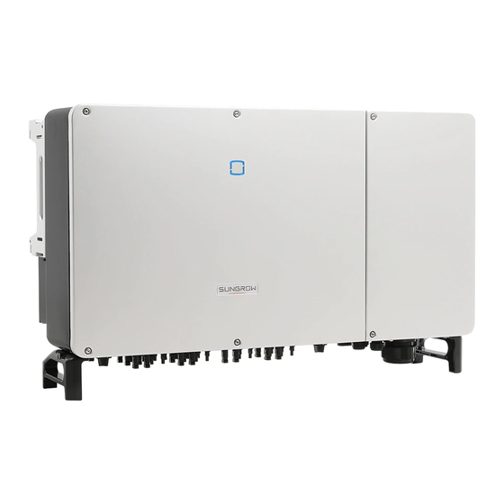
2 Product Description Product Introduction Model Description The model description is as follows(Take SG110CX-20 as an example): Appearance The following figure shows the appearance of the inverter. The image shown here is for reference only. The actual product received may differ. - Page 18 2 Product Description User Manual figure 2-2 Inverter Appearance * The image shown here is for reference only. The actual product received may differ. Description Name LED indicator HMI interface to indicate the present working state of the panel inverter. Warning symbols, nameplate, and QR code.
-
Page 19: Symbols On The Product
User Manual 2 Product Description Symbols on the Product Symbol Explanation Do not dispose of the inverter together with household waste. TÜV mark of conformity. CE mark of conformity. EU/EEA Importer. Regulatory compliance mark. CGC-SOLAR mark of conformity. Danger to life due to high voltages! Only qualified personnel can open and service the inverter. -
Page 20: Dc Switch
The DC switch is used to disconnect the DC current safely whenever necessary. The SG110CX-NI is not equipped with DC switch. The SG110CX/SG110CX-20 is equipped with three DC switches, and each DC switch con- trols its corresponding DC terminals. Turn the DC switches to the ON position before restarting the inverter. -
Page 21: Function Description
User Manual 2 Product Description figure 2-4 Circuit Diagram • The DC SPD provides a discharge circuit for the DC side over-voltage power to prevent it from damaging the internal circuits of the inverter. • EMI filters can filter out the electromagnetic interference inside the inverter to ensure that the inverter meets the requirements of electromagnetic compatibility standards. - Page 22 2 Product Description User Manual The inverter can provide export control but will require the use of a external smart meter. The export control functionality has not been tested to AS/NZS 4777.2:2020. Protection Function The protective functions are integrated in the inverter, including anti-island protection, LVRT/ HVRT, DC reversed polarity protection, AC short circuit protection, leakage current protec- tion, DC overvoltage/overcurrent protection, etc.
- Page 23 User Manual 2 Product Description AFCI Function(Optional) • AFCI activation This function can be enabled to detect whether arc occurs in the DC circuit of the inverter. • AFCI self-test This function is intended to detect whether the AFCI function of the inverter is normal.
-
Page 24: Unpacking And Storage
• Check the inner contents for damage after unpacking. Contact SUNGROW or the transport company in case of any damage or incompleteness, and provide photos to facilitate services. Do not dispose of the original packing case. It is recommended to store the device in the original packing case when the product is decommissioned. - Page 25 User Manual 3 Unpacking and Storage • Do not store the inverter in places susceptible to direct sunlight, rain, and strong electric field. • Do not place the inverter in places with items that may affect or damage the inverter. •...
-
Page 26: Mechanical Mounting
Mechanical Mounting Respect all local standards and requirements during mechanical installation. Safety during Mounting Make sure there is no electrical connection before installation. Before drilling, avoid the water and electricity wiring in the wall. Poor installation environment will affect system performance! •... -
Page 27: Environment Requirements
User Manual 4 Mechanical Mounting 4.2.1 Environment Requirements • The installation environment must be free of inflammable or explosive materials. • The location should be not accessible to children. • The ambient temperature and relative humidity must meet the following requirements. •... -
Page 28: Angle Requirements
4 Mechanical Mounting User Manual 4.2.3 Angle Requirements Install the inverter vertically or at the maximum allowable rear tilt angle. Do not install the in- verter horizontally, forward, excessively backward, sideways, or upside down. Inverters in floating plants cannot be installed at a back tilt. -
Page 29: Clearance Requirements
User Manual 4 Mechanical Mounting In case the installation site is a level surface, mount the inverter to the bracket to meet the mounting angle requirements, as shown in the figure below. Take the following items into account when designing the bracket scheme: •... -
Page 30: Installation Tools
4 Mechanical Mounting User Manual In case of back-to-back installation, reserve specific clearance between the two inverters. Install the inverter at an appropriate height for ease of viewing LED indicator and operating switch(es). Installation Tools Installation tools include but are not limited to the following recommended ones. If necessary, use other auxiliary tools on site. -
Page 31: Moving The Inverter
User Manual 4 Mechanical Mounting Hammer drill Pliers Marker Level (φ12, φ14) Rubber mallet Socket wrench set Wrench Wrist strap (16mm) (13 mm, 16 mm) Wire cutter Wire stripper Hydraulic plier Heat gun MC4 terminal MC4 terminal Multimeter RJ45 crimping tool crimping pliers wrench ≥... -
Page 32: Manual Transport
4 Mechanical Mounting User Manual • Always be aware of the weight of the inverter. • Lift the inverter using the handles positioned on both sides of the inverter. • Move the inverter by one or two people or by using a proper transport tool. •... - Page 33 User Manual 4 Mechanical Mounting step 2 Lead the sling through the two lifting rings and fasten the tie-down strap. step 3 Hoist the inverter, and stop to check for safety when the inverter is 100mm above the ground. Continue hoisting the device to the destination after ensuring the safety. step 4 Remove the lifting rings and reassemble the sealing screws released in Step 1.
-
Page 34: Installing The Mounting-Bracket
4 Mechanical Mounting User Manual Installing the mounting-bracket Inverter is installed on the wall and bracket by means of mounting bracket. The expansion plug set shown below is recommended for the installation. figure 4-1 Dimensions of mounting-bracket 4.5.1 PV Bracket-Mounted Installation step 1 Assemble the mounting-bracket by using the connecting bar. -
Page 35: Wall-Mounted Installation
User Manual 4 Mechanical Mounting Components Description Mounting-bracket – Full threaded bolt M10*45 – Metal bracket – Flat washer Spring washer – Hex nuts - - End 4.5.2 Wall-Mounted Installation step 1 Assemble the mounting-bracket by using the connecting bar. step 2 Level the assembled mounting-bracket by using the level, and mark the positions for drilling holes on the installation site. -
Page 36: Installing The Inverter
4 Mechanical Mounting User Manual Components Description – Wall Fastening the bolt in the sequence of nut, spring wash- Expansion bolt er, slat washer Mounting-bracket – - - End Installing the Inverter step 1 Take out the inverter from the packing case. step 2 Hoist the inverter to the installation position when necessary (refer to ""4.4.2 Hoisting Trans- port""). -
Page 37: Electrical Connection
Electrical Connection Safety Instructions The PV string will generate lethal high voltage when exposed to sunlight. • Operators must wear proper personal protective equipment during electrical connections. • Must ensure that cables are voltage-free with a measuring instrument before touching DC cables. •... -
Page 38: Terminal Description
5 Electrical Connection User Manual • All vacant terminals must be covered with waterproof covers to prevent affect- ing the protection rating. • When the wiring is completed, seal the gap of cable inlet and outlet holes with fireproof / waterproof materials such as fireproof mud to prevent foreign matter or moisture from entering and affecting the long-term normal operation of the inverter. - Page 39 User Manual 5 Electrical Connection figure 5-1 Terminal Description(For a multi-core cable) figure 5-2 Terminal Description(For four single-core cables) * The image shown here is for reference only. The actual product received may differ.
-
Page 40: Electrical Connection Overview
5 Electrical Connection User Manual Item Terminal Mark Note PV terminals + / - MC4 PV connector RS485 communication, digital input/output DI/ Communica- COM1 / 2 / 3 tion terminal COM4 For communication module connection. AC wiring Used for AC output cable connection. terminal Standby Used for internal grounding. - Page 41 To purchase the AC sealing plate accessory, contact your dis- tributor. If the distributor is unable to provide the AC sealing plate accessory, contact SUNGROW. figure 5-3 Spare AC Sealing Plate Inverter for Australia and New Zealand are equipped with the four-core sealing...
-
Page 42: Crimp Ot / Dt Terminal
5 Electrical Connection User Manual table 5-2 PE Wire Requirements PE Wire PE Wire Cross Cross Note Section S Section The specifications are valid only when the phase wire and PE wire use the same material. If otherwise, ensure S / 2 S >... -
Page 43: External Protective Grounding Connection
User Manual 5 Electrical Connection figure 5-4 Aluminium cable terminal connection sequence 1. Copper to Aluminium adapter terminal 2. Flange nut 3. Aluminium cable Ensure that the selected terminal can directly contact with the copper bar. If there are any problems, contact the terminal manufacturer. Ensure that the copper bar is not in direct contact with the aluminum wire. -
Page 44: External Protective Grounding Requirements
AC side grounding terminal are reliably grounded. The grounding connection can be made by other means if they are in accordance with the local standards and regulations, and SUNGROW shall not be held liable for the possible consequences. -
Page 45: Opening The Wiring Compartment
User Manual 5 Electrical Connection The grounding screws have been anchored to the side of the inverter before deliv- ery, and do not need to be prepared. There are two grounding terminals. Use one of them to ground the inverter. - - End Opening the Wiring Compartment step 1 Release two screws on the front cover of the wiring compartment with supplied Allen wrench. -
Page 46: Ac Cable Connection
AC Circuit Breaker An independent circuit breaker or fuse should be installed on the output side of the inverter to ensure safe disconnection from the grid. Recommended rated voltage Inverter Model Recommended rated current SG110CX 400V 200A SG110CX-20 400V 200A... -
Page 47: Requirements For Ot/Dt Terminal
User Manual 5 Electrical Connection MV Transformer The MV transformer used together with the inverter should meet the following requirements: • The transformer may be a distribution transformer, and it must be designed for the typical cyclical loads of a PV system (load in the day and no load at night). •... -
Page 48: Connection Procedure(For A Multi-Core Cable)
5 Electrical Connection User Manual • Dimensions: a≤46 mm / 13 mm≤b≤15.5 mm / c≤22 mm OT/DT Terminal of PE Wire • Specification: M8 / M10. 5.7.3 Connection Procedure(For a multi-core cable) In this manual, description is given by using five-core cable as an example. The wiring of the four-core cable is the same. - Page 49 User Manual 5 Electrical Connection step 5 Strip the protection layer and insulation layer by specific length, as described in the figure below. step 6 Make the cable and crimp OT/DT terminal. step 7 Secure the wires to corresponding terminals. Note the terminal positions of PE wire and N wire.
- Page 50 5 Electrical Connection User Manual Ensure that the depth L of the socket used is not less than 28mm. step 8 Gently pull the cable backwards to ensure firm connection, and fasten the swivel nut clockwise. If the PE cable is an independent single-core cable, it should be inserted into the cabinet through the standby grounding terminal.
-
Page 51: Connection Procedure(L1/L2/L3/N, For Four Single-Core Cables)
User Manual 5 Electrical Connection - - End 5.7.4 Connection Procedure(L1/L2/L3/N, For four single-core cables) step 1 Open the wiring compartment. For details, refer to"5.6 Opening the Wiring Compartment". step 2 Disconnect the AC-side circuit breaker and prevent it from inadvertent reconnection. step 3 Loosen the swivel nut of the AC waterproof connector and select a seal according to the ca- ble outer diameter, remove the inner sealing ring if the cable diameter is larger than 22 mm. - Page 52 5 Electrical Connection User Manual step 5 Strip the protection layer and insulation layer by specific length, as described in the figure below. step 6 Make the cable and crimp OT/DT terminal. step 7 Secure the wires to corresponding terminals. Note the terminal positions of PE wire and N wire.
-
Page 53: Connection Procedure(L1/L2/L3/Pe, For Four Single-Core Cables)
User Manual 5 Electrical Connection step 9 Install the protection cover - - End 5.7.5 Connection Procedure(L1/L2/L3/PE, For four single-core cables) step 1 Open the wiring compartment. For details, refer to"5.6 Opening the Wiring Compartment". step 2 Disconnect the AC-side circuit breaker and prevent it from inadvertent reconnection. step 3 Loosen the swivel nut of the AC waterproof connector and select a seal according to the ca- ble outer diameter, remove the inner sealing ring if the cable diameter is larger than 22 mm . - Page 54 5 Electrical Connection User Manual step 4 Remove the protection cover and store the released screws properly. step 5 Strip the protection layer and insulation layer by specific length, as described in the figure below. step 6 Make the cable and crimp OT/DT terminal. step 7 Secure the wires to corresponding terminals.
- Page 55 User Manual 5 Electrical Connection Ensure that the depth L of the socket used is not less than 28mm. step 8 Gently pull the cable backwards to ensure firm connection, and fasten the swivel nut clockwise. step 9 Install the protection cover - - End...
-
Page 56: Dc Cable Connection
The damage caused by this is not covered by the warranty. • Electric arc or contactor over-temperature may occur if the PV connectors are not firmly in place, and SUNGROW shall not be held liable for any damage caused. •... -
Page 57: Pv Input Configuration
Each PV input area includes two DC inputs DC1 and DC2. For the best use of DC power, DC1 and DC2 should be the same in PV string structure, including the type, number, tilt, and orientation of the PV modules. Max. Current for Input Type Open Circuit Voltage Limit Connector SG110CX 1100V SG110CX-20 1100V SG110CX-NI 1100V... -
Page 58: Assembling The Pv Connectors
Use MC4-Evo2 DC terminals if the maximum input voltage is greater than 1,000 V. To purchase the MC4-Evo2 DC terminals, contact SUNGROW. • Select appropriate DC terminals as required above. Otherwise, SUNGROW shall be held no liability for the damage caused. To ensure IP66 protection, use only the supplied connector. -
Page 59: Installing The Pv Connector
User Manual 5 Electrical Connection step 4 Check for polarity correctness. - - End 5.8.3 Installing the PV Connector step 1 Rotate the DC switch(if there is) to “OFF” position. step 2 Check the cable connection of the PV string for polarity correctness and ensure that the open circuit voltage in any case does not exceed the inverter input limit of 1,100V. -
Page 60: Rs485 Connection
5 Electrical Connection User Manual step 4 Follow the foregoing steps to connect PV connectors of other PV strings. step 5 Seal any unused PV terminal with a terminal cap. If the PV string is equipped with the optimizer, please refer to the optimizer manual for elec- trical connections and make sure that the polarity of the optimizer cables is correct. -
Page 61: Rs485 Communication System
User Manual 5 Electrical Connection Definition GND, shielded earthing point RS485 A OUT, RS485A differential signal+ RS485 B OUT, RS485B differential signal- GND, shielded earthing point table 5-4 RS485_1 port terminal definition (RJ45) Definition PIN1~2 RS485 B, RS485B differential signal- PIN3 PIN4~5 RS485 A, RS485A differential signal+... - Page 62 5 Electrical Connection User Manual figure 5-5 Multi-inverter Communication System【RS485_1 Interface(Terminal Block)】 figure 5-6 Multi-inverter Communication System【RS485_1 Interface(RJ45)】 When more than 15 inverters are connected to the same daisy chain, in order to ensure the communication quality, the Logger at the first end of the daisy chain needs to be equipped with a terminal resistor of 120Ω, the inverter at the last end needs to be equipped with a RS485-dip switch (SW1), and the shielding layer of the communication cable should be sin- gle-point grounded.
-
Page 63: Connection Procedure(Terminal Block)
User Manual 5 Electrical Connection figure 5-7 Configuration of Dip Switch (N≥15) The length of the RS485 cable and twisted pair cable should be no longer than 1,200m. If multiple inverters are connected to the data collector Logger3000, the number of permissible daisy chains and the number of devices allowed to be connected should meet the requirements (refer to the user manual for the Logger3000). -
Page 64: Connection Procedure (Rj45 Ethernet Port)
5 Electrical Connection User Manual Outer Diameter D(mm) Seal 4.5 ~ 6 6 ~ 12 a + b 12 ~ 18 step 3 Secure the cable to the terminal base. step 4 Insert the terminal base into the corresponding terminal. step 5 Pull the cable gently to make sure it is secured, tighten the swivel nut clockwise. - Page 65 User Manual 5 Electrical Connection Outer Diameter D(mm) Seal 4.5 ~ 6 6 ~ 12 a + b 12 ~ 18 step 2 Strip the insulation layer of the Ethernet cable with a wire stripper, and insert the signal wires to the RJ45 connector(Pin 3 and Pin 6 are for communication connection).
-
Page 66: Dry Contact Connection
5 Electrical Connection User Manual - - End 5.10 Dry Contact Connection Dry contact cables require a cross section of 1 mm to 1.5 mm The connection procedure of the dry contact is the same as that of the RS485 ter- minal block. - Page 67 User Manual 5 Electrical Connection figure 5-8 Normal open contact figure 5-9 Normal close contact Devices connected to the relay should comply with related requirements: AC-Side Requirements DC-Side Requirements Max. voltage: 125Vac Max. voltage: 30Vdc Max. current: 5A Max. current: 5A DI terminal (emergency stop dry contact): the dry contact can be configured to be an emergency stop contact.
-
Page 68: Wiring Procedure
5 Electrical Connection User Manual figure 5-10 Local stop contact figure 5-11 Daisy chain topology When wiring DI dry contacts, ensure that the maximum wiring distance meet the require- ments in "10.2 Wring Distance of DI Dry Contact". 5.10.2 Wiring Procedure Refer to the wiring of terminal block described in chapter"5.9.3 Connection Procedure(Termi- nal Block)"... -
Page 69: Connection Procedure
20 kΩ Enable the DRM function through the iSolarCloud App. If there are any problems, contact your distributor first. If the problem persists, contact SUNGROW. The DRM function is only applicable to devices for Australia and New Zealand. 5.11.2 Connection Procedure step 1 Strip the insulation layer of the Ethernet cable with a wire stripper, and insert the signal wires to the RJ45 connector. -
Page 70: Closing The Wiring Compartment
- - End 5.13 Communication Module Connection (optional) Connect the communication module produced by SUNGROW to the communication acces- sory port. After successful connection, information such as power generation and running state of the inverter can be viewed via the APP on the phone. - Page 71 User Manual 5 Electrical Connection *The image shown here is for reference only. The actual product you receive may differ. Once the communication module is in use, do not connect the inverter to a 3rd party data logger at the same time via RS485. For details on module installation and configuration, refer to the manual delivered together with the module.
-
Page 72: Commissioning
Commissioning Inspection before Commissioning Check the following items before starting the inverter: • All equipment has been reliably installed. • DC switch(es) and AC circuit breaker are in the "OFF" position. • The ground cable is properly and reliably connected. •... -
Page 73: Isolarcloud App
iSolarCloud App Brief Introduction The iSolarCloud App can establish communication connection to the inverter via the Blue- tooth, thereby achieving near-end maintenance on the inverter. Users can use the App to view basic information, alarms, and events, set parameters, or download logs, etc. *In case the communication module Eye, WiFi or WiNet-S is available, the iSolarCloud App can also establish communication connection to the inverter via the mobile data or WiFi, thereby achieving remote maintenance on the inverter. -
Page 74: Function Overview
7 iSolarCloud App User Manual Function Overview The App provides parameter viewing and setting functions, as shown in the following figure. figure 7-1 App function tree map Login 7.4.1 Requirements The following requirements should be met: • The AC or DC side of the inverter is powered-on. •... - Page 75 User Manual 7 iSolarCloud App • Tap "Manual connection" and select "Others" on the bottom of the page, the Bluetooth search page will automatically pop up, and select the inverter to be connected according to the SN on the nameplate on the side of the inverter body. figure 7-2 Bluetooth Connection step 3 Enter the identity verification screen after the Bluetooth connection is established.
- Page 76 If the dis- tributor is unable to provide the required information, contact SUNGROW. step 4 If the inverter is not initialized, you will enter the quick setting screen of initializing protection parameter.
- Page 77 User Manual 7 iSolarCloud App In the European region, such as Sweden, Ireland, Hungary, Portugal, Romania, Greece, Ukraine etc. whose grid code complies with EN50549, select the parame- ter EN50549_1 (LV grid- connection) or EN50549_2 (MV grid-connection) with proper manual settings. In the Brazilian region, set the country code as "Brazil".
-
Page 78: Home Page
7 iSolarCloud App User Manual Grid Type Network Service Provider CitiPower & Powercor • ≤ 5 kVA for single-phase & 30 kVA for three-phase • > 30 kVA three-phase United Energy • UE-ST-2008.1: ≤ 10 kW for single- phase & 30 kW for three-phase •... - Page 79 User Manual 7 iSolarCloud App figure 7-6 Home Page table 7-2 Home Page Description Designation Description System date and time of the inverter. Date and time Present operation state of the inverter. For details, refer to Inverter state "table 7-3 Description of Inverter State".
- Page 80 7 iSolarCloud App User Manual table 7-3 Description of Inverter State Description State After being energized, the inverter tracks the PV arrays’ maximum power point (MPP) and converts the DC power into AC power. This is the nor- mal operation mode. Stop The inverter is stopped.
-
Page 81: Run Information
User Manual 7 iSolarCloud App Run Information Tap Run Information on the navigation bar to enter the screen showing running information, slide the screen upwards to view all detailed information. table 7-5 Run Information Classifica- Description Parameter tion String n Voltage The input voltage of the n string Information... -
Page 82: Records
7 iSolarCloud App User Manual Classifica- Description Parameter tion B-C Line Voltage C-A Line Voltage Phase A Current Phase B Current Phase Current Phase C Current Records Tap Records on the navigation bar to enter the screen showing event records, as shown in the following figure. - Page 83 User Manual 7 iSolarCloud App figure 7-9 Detailed Fault Alarm Information Yield Record Tap Yield Record to enter the screen showing daily power generation , as shown in the fol- lowing figure. figure 7-10 Power Curve The App displays power generation records in a variety of forms, including daily power gen- eration graph, monthly power generation histogram, annual power generation histogram and total power generation histogram.
-
Page 84: More
7 iSolarCloud App User Manual Description Parameter Monthly energy Shows the power output every month in a year. histogram Annual energy Shows the power output every year. histogram Tap the time bar on the top of the screen to select a time segment and view the correspond- ing power curve. -
Page 85: Operation Parameters
User Manual 7 iSolarCloud App figure 7-12 System Parameters * The image shown here is for reference only. Boot/Shutdown Tap Boot/Shutdown to send the boot/shutdown instruction to the inverter. For Australia and New Zealand, when the DRM state is DRM0, the "Boot" option will be prohibited. - Page 86 7 iSolarCloud App User Manual figure 7-14 PID Setting table 7-7 PID Parameter Description Description Parameter Set enabling/disabling of the PID night recovery function. PID night PID Recovery recovery function operates between 22:00 pm and 5:00 am by default. If ISO impedance abnormality or PID function exception is de- tected during running of the PID function, the inverter reports a Clear PID alarm PID false alarm and reminds the user to take corresponding meas-...
-
Page 87: Power Regulation Parameters
User Manual 7 iSolarCloud App figure 7-16 NS Protection(Passive Valid) 7.8.3 Power Regulation Parameters Active Power Regulation Tap Settings→Power Regulation Parameters→Active Power Regulation to enter the screen, as shown in the following figure. figure 7-17 Active Power Regulation table 7-8 Active Power Regulation Definition/Setting Range Parameter... - Page 88 7 iSolarCloud App User Manual Definition/Setting Range Parameter Description Active power rising The rise rate of inverter active 3%/min~6000%/min gradient power per minute. Active power setting Switch for enabling/disabling Enable/Disable persistence the function of saving output limited power. Active power limit The switch for limiting output Enable/Disable power.
- Page 89 User Manual 7 iSolarCloud App figure 7-18 Reactive Power Regulation table 7-9 Reactive Power Regulation Definition/Setting Range Parameter Description Reactive power genera- Switch for enabling/disabling Enable/Disable tion at night Q at night function. Reactive power ratio at Reactive power ratio set for -100%~0%/ night the Q at night function.
- Page 90 7 iSolarCloud App User Manual Definition/Setting Range Parameter Description QP_P3 Output power at P3 on the Q 20.0%~100.0% (P) mode curve (in percentage) QP_K1 Power factor at P1 on the Q(P) Curve A/Curve mode curve C:0.800~1.000 Curve B: [-0.600~0.600]*Ac- tive Overload Rate/1000 QP_K2 Power factor at P2 on the Q(P) Curve A/Curve C:...
- Page 91 User Manual 7 iSolarCloud App Definition/Setting Range Parameter Description QU_V2 Pre-set grid voltage U2 that is 80.0%~100.0% reactive according to the grid voltage. QU_Q2 Pre-set proportion of reactive [-60.0%-60.0%]* Overload power according to the grid Rate/1000 voltage U2. QU_V3 Pre-set grid voltage U3 that is 100.0%~120.0% reactive according to the grid voltage.
-
Page 92: Communication Parameters
7 iSolarCloud App User Manual figure 7-19 Q(U) Curve figure 7-20 Q(P) Curve 7.8.4 Communication Parameters Serial Port Parameters Tap Settings→Communication Parameters→Serial Port Parameters to enter the corre- sponding interface, as shown in the following figure. figure 7-21 Serial Port Parameters table 7-10 Serial Port Parameters Range Parameter... -
Page 93: Firmware Update
User Manual 7 iSolarCloud App figure 7-22 MPLC Parameters table 7-11 MPLC Parameters Range Parameter Band Num Band1, Band2 Array ID 1–255 Winding ID 1–10 7.8.5 Firmware Update To avoid download failure due to poor on-site network signal, it is recommended to download the firmware package to the mobile device in advance. -
Page 94: Password Changing
7 iSolarCloud App User Manual step 8 Tap the upgrade package file, a prompt box will pop up asking you to upgrade the firmware with the file, tap CONFIRM to perform the firmware upgrade. step 9 Wait for the file to be uploaded. When the upgrade is finished, the interface will inform you of the upgrade completion. - Page 95 User Manual 7 iSolarCloud App figure 7-23 Change Password The password shall consisit of 8–20 digits, including letters and numbers.
-
Page 96: System Decommissioning
System Decommissioning Disconnecting the Inverter Danger of burns! Even if the inverter is shut down, it may still be hot and cause burns. Wear protec- tive gloves before operating the inverter after it cools down. For maintenance or other service work, the inverter must be switched off. Proceed as follows to disconnect the inverter from the AC and DC power sources. -
Page 97: Disposal Of The Inverter
User Manual 8 System Decommissioning step 2 Refer to"4 Mechanical Mounting", to dismantle the inverter in reverse steps. step 3 If necessary, remove the wall-mounting bracket from the wall. step 4 If the inverter will be used again in the future, please refer to "3.2 Inverter Storage"... -
Page 98: Troubleshooting And Maintenance
App or the LCD. Modify the overvoltage protection values with the con- sent of the local electric power operator. 3. Contact Sungrow Customer Service if the pre- ceding causes are ruled out and the fault persists. Generally, the inverter will be reconnected to the grid after the grid returns to normal. - Page 99 2. Check whether the protection parameters are appropriately set via the App or the LCD. 3. Contact Sungrow Customer Service if the pre- ceding causes are ruled out and the fault persists. Generally, the inverter will be reconnected to the grid after the grid returns to normal.
- Page 100 App or the LCD. 3. Contact Sungrow Customer Service if the pre- ceding causes are ruled out and the fault persists. 1. Check whether the corresponding string is of reverse polarity.
- Page 101 3. Check if the DC fuse is damaged. If so, replace Alarm the fuse. 4. Contact Sungrow Customer Service if the pre- ceding causes are ruled out and the alarm persists. *The code 548 to code 563 are corresponding to string 1 to string 16 respectively.
- Page 102 If so, replace the dam- aged cable and secure terminals to ensure a reli- able connection. 5. Contact Sungrow Customer Service if the pre- ceding causes are ruled out and the fault persists. 1. Check whether the AC cable is correctly connected.
- Page 103 2. Reconnect the communication cable of the cation Abnormal meter. Alarm 3. Contact Sungrow Customer Service if the pre- ceding causes are ruled out and the alarm persists. 1. Check whether the output port is connected to actual grid. Disconnect it from the grid if so.
- Page 104 Close the AC and DC switches in turn 15 248–255, 300– minutes later and restart the system. 322, 324–328, 3. Contact Sungrow Customer Service if the pre- 401–412, 600– ceding causes are ruled out and the fault persists. 603, 605, 608, 612, 616, 620, 622–624, 800,...
- Page 105 Close the AC and DC switches in turn 15 364-395 minutes later and restart the system. Overvoltage Fault 2. If the fault persists, please contact Sungrow Power Customer Service. 1. Check whether the number of PV modules of the corresponding string is less than other strings.
-
Page 106: Maintenance
3. Do not reinsert the faulty strings before the grounding fault is cleared; 4. If the fault is not caused by the foregoing rea- sons and still exists, contact Sungrow Customer Service. 1. It is prohibited to disconnect the DC switch when the DC current is greater than 0.5 A when... -
Page 107: Routine Maintenance
To avoid the risk of electric shock, do not perform any other maintenance opera- tions beyond this manual. If necessary, contact your distributor first. If the problem persists, contact SUNGROW. Otherwise, the losses caused is not covered by the warranty. -
Page 108: Cleaning Air Inlet And Outlet
9 Troubleshooting and Maintenance User Manual Item Method Period Check whether the cable entry is in- sufficiently sealed or the gap is exces- Cable entry Once a year sively large, and reseal the entry when necessary. Check whether all cable are firmly connected in place. - Page 109 User Manual 9 Troubleshooting and Maintenance step 3 Press the tab of the latch hook, unplug the cable connection joint outwards, and loosen the screw on the fan holder. step 4 Pull out the fan module, clean the fans with soft brush or vacuum cleaner, and replace them when necessary.
- Page 110 9 Troubleshooting and Maintenance User Manual step 5 Reinstall the fan back to the inverter in reverse order and restart the inverter. - - End...
-
Page 111: Appendix
10 Appendix 10.1 Technical Data SG110CX SG110CX-NI Parameters Input (DC) Recommended max. 147 kW PV input power Max. PV input 1100 V voltage Min.PV input voltage/ Start-up input 200 V / 250 V voltage Nominal input 585 V voltage MPP voltage range 200 –... - Page 112 10 Appendix User Manual SG110CX SG110CX-NI Parameters Power factor at nomi- nal power / Adjust- >0.99 / 0.8 leading – 0.8 lagging able power factor Feed-in phases / AC 3 / 3–PE connection Efficiency Max. efficiency / 98.7% / 98.5%...
- Page 113 User Manual 10 Appendix SG110CX SG110CX-NI Parameters Operating ambient -30 to 60 ℃ (> 50 ℃ derating) temperature range Allowable relative hu- 0–100% midity range Cooling method Smart forced air cooling Max. operating 4000 m (> 3000 m derating) altitude...
- Page 114 10 Appendix User Manual SG110CX-20 Parameters AC voltage range 320 – 460V Nominal grid frequency / Grid frequency 50 Hz / 45 – 55 Hz, 60 Hz / 55 – 65 Hz range Harmonic (THD) < 3 % (at nominal power) Power factor at nominal power / Adjustable 0.99 / 0.8 leading –...
-
Page 115: Wring Distance Of Di Dry Contact
User Manual 10 Appendix SG110CX-20 Parameters Allowable relative humidity range 0 – 100 % Cooling method Smart forced air cooling Max. operating altitude 4000 m (> 3000 m derating) Display LED, Bluetooth+APP Communication RS485 / Optional: WLAN, Ethernet DC connection type MC4 (Max. -
Page 116: Quality Assurance
300Ω; and when there are multiple inverters connected in the daisy chain, en- sure that the impedance is less than 300Ω/number of inverter. 10.3 Quality Assurance When product faults occur during the warranty period, SUNGROW will provide free service or replace the product with a new one. -
Page 117: Contact Information
• The customer shall give SUNGROW a reasonable period to repair the faulty device. Exclusion of Liability In the following circumstances, SUNGROW has the right to refuse to honor the quality guarantee: • The free warranty period for the whole machine/components has expired. - Page 118 Sungrow Power Supply Co., Ltd. www.sungrowpower.com...
Need help?
Do you have a question about the SG110CX and is the answer not in the manual?
Questions and answers