
Related Manuals for GEM 1435 ePos


Summary of Contents for GEM 1435 ePos
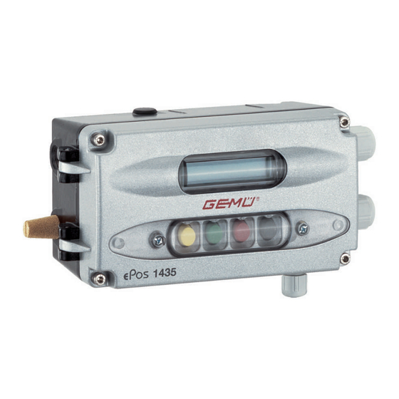
- Page 1 GEMÜ 1435 ePos Intelligent electro-pneumatic positioner Operating instructions further information webcode: GW-1435...
- Page 2 All rights including copyrights or industrial property rights are expressly reserved. Keep the document for future reference. © GEMÜ Gebr. Müller Apparatebau GmbH & Co. KG 28.08.2023 GEMÜ 1435 ePos 2 / 71 www.gemu-group.com...
-
Page 3: Quick Commissioning
(for example LEAKAGE). ▶ Manual initialization with sequential movement through the menu by the operator or, if possible, acknowledging the error message to repeat the step may help here (see “Carrying out initialization“, page 51). www.gemu-group.com 3 / 71 GEMÜ 1435 ePos... - Page 4 If the message "INIT OK" appears, the product is ready for operation and can be set to the desired operating mode. – Operating mode A: AUTO – reacts to the externally specified set value. – Operating mode B: MANUAL – the valve position can be specified manually using the keys. GEMÜ 1435 ePos 4 / 71 www.gemu-group.com...
-
Page 5: Table Of Contents
3 Safety information ..........17.2.2 Parameter overview ......4 Product description ..........17.2.3 Menu 1 Service ......... 5 GEMÜ CONEXO ............ 17.2.4 Menu 2 SetBasics ......6 Intended use ............17.2.5 Menu 3 SetFunction ......17.2.6 Menu 4 SetCalibration ..... -
Page 6: General Information
▶ Non-observance can cause damage to 2.3 Definition of terms property. Working medium The medium that flows through the GEMÜ product. The following symbols for the specific dangers can be used Control function within a warning note: The possible actuation functions of the GEMÜ product. -
Page 7: Safety Information
Connection and mount- 6. Define the areas of responsibility. ing to NAMUR is also possible. Therefore, the GEMÜ 1435 7. Observe the safety data sheets. ePos is an optimal solution for control tasks with high require- ments, especially in applications with harsh environmental 8. - Page 8 Double acting: ven- Double acting: pres- surized * Only when using the 4–20 mA type of set value (parameter setting) This fail safe function is not a substitute for specific plant safety requirements. GEMÜ 1435 ePos 8 / 71 www.gemu-group.com...
-
Page 9: Gemü Conexo
The valve position and the integrated travel sensor can be monitored via the electrical connections. The pneumatic actu- ator is directly operated and controlled by means of the pilot valves. ● Use the product in accordance with the technical data. www.gemu-group.com 9 / 71 GEMÜ 1435 ePos... -
Page 10: Order Data
2 Fieldbus Without 3 Accessory Accessory 4 Action Single acting 5 Explosion-proof class Without explosion-proof rating 6 Option Without 7 Flow rate Electro-pneumatic, 50 l/min 8 Special specification Without 9 CONEXO Without GEMÜ 1435 ePos 10 / 71 www.gemu-group.com... -
Page 11: Technical Data
50 Nl/min (Flow rate code 01) 90 Nl/min (Flow rate code 02) Air consumption: 0 Nl/min (when idle) 8.5 Mechanical data Installation position: Optional Protection class: IP 65 acc. to EN 60529 Weight: 1.7 kg www.gemu-group.com 11 / 71 GEMÜ 1435 ePos... - Page 12 0–10 V: 100 kΩ Accuracy/linearity: ≤ ±0.3% of full flow Temperature drift: ≤ ±0.5% of full flow Resolution: 12 bit Reverse battery protec- tion: Overload proof: Yes (up to ± 24 V DC) GEMÜ 1435 ePos 12 / 71 www.gemu-group.com...
- Page 13 Resistance range of re- 1 to 10 kΩ mote potentiometers: Input voltage 0 to U range: Input resistance: 330 kΩ Accuracy/linearity: ≤ ±0.3% of full flow Temperature drift: ≤ ±0.3% of full flow Resolution: 12 bit www.gemu-group.com 13 / 71 GEMÜ 1435 ePos...
- Page 14 Set value input (mA / V) During initialization, the 1435 ePos positioner automatically detects the control function of the valve and adjusts itself by default so that the valve is closed when the signal is 0/4 mA or 0 V.* The assignment can be changed subsequently by means of parameters.
-
Page 15: Dimensions
9.2 Dimensions of the travel sensor, mounting options and mounting facilities For dimensions of travel sensors 4231 and 4232, which are used to measure the travel from the process valve, as well as the mounting bracket for wall mounting the 1435, see the 1435 ePos datasheet. www.gemu-group.com 15 / 71 GEMÜ... -
Page 16: Manufacturer's Information
**If a threaded adapter is included, it must be screwed into 4. Do not store solvents, chemicals, acids, fuels or similar the actuator top of the process valve fluids in the same room as GEMÜ products and their spare The process described below refers to the mounting kit parts. - Page 17 5. Screw the appropriate adapter 3.1 into the actuator open- ing as far as it will go and tighten. ð The mounting bracket is mounted later with the second adapter (see chapter 10.6, Direct mounting with mounting bracket type 4). www.gemu-group.com 17 / 71 GEMÜ 1435 ePos...
-
Page 18: Assembly On Quarter Turn Actuators
4. Fit the positioner in a suitable location. NOTICE Mounting bracket ▶ The GEMÜ 1445 000 ZMP mounting bracket, which is available separately, can be used for this. GEMÜ 1435 ePos 18 / 71 www.gemu-group.com... - Page 19 3. Place the adapter 4 onto the shaft of the rotary travel sensor 2 without twisting the shaft. 6. Note the direction of the scale 8. ð View from below of the travel sensor 7 with mounting bracket 6. www.gemu-group.com 19 / 71 GEMÜ 1435 ePos...
- Page 20 Potentiometer shaft marking Actuator shaft (from above) Item Name Rotary potentiometer shaft Mounting bracket Adapter Quarter turn actuator Rotary potentiometer connection Rotary travel sensor Butterfly disc: Closed NAMUR adapter Actuator Cable gland Rotary potentiometer GEMÜ 1435 ePos 20 / 71 www.gemu-group.com...
- Page 21 (see “Checking the mechanical Mounting bracket mounting“, page 22). ▶ The GEMÜ 1445 000 ZMP mounting bracket, which is available separately, can be used for this. 5. Mount the mounting bracket 1 on the actuator 2 using the screws, washers and spring washers provided.
-
Page 22: Checking The Mechanical Mounting
If the travel range is incorrect (determined by checking the attachment), loosen the two screws slightly and twist the travel sensor. Set the travel up correctly and tighten the screws again. GEMÜ 1435 ePos 22 / 71 www.gemu-group.com... -
Page 23: Electrical Connection
NOTICE ▶ GEMÜ 4231 and 4232 travel sensors with the M12 plug connection can be used for this version. 1. Connect the connection cable with the appropriate travel sensor connector to the X3 M12 built-in socket on the side of the positioner. - Page 24 Error message output GND out ┴ 1) Core colours when using an external travel sensor GEMÜ 4231 or 4232. Connect in the specified order. Other external travel sensors may have different core colours. GEMÜ 1435 ePos 24 / 71 www.gemu-group.com...
- Page 25 * For set value input Uw = 0 - 10 V on-site rewiring is required Connection X3 (for travel sensor connection) Signal name UP+, actual value supply 10 V DC UPsig, actual value input 0–10 V DC UP-, actual value supply GND n.c. n.c. www.gemu-group.com 25 / 71 GEMÜ 1435 ePos...
-
Page 26: Pneumatic Connection
G1/4 Exhaust air throttle for 2 Exhaust air throttle for 4* Check valve Working connection for pro- cess valve Working connection for pro- cess valve* * Only with double acting action (code 3) GEMÜ 1435 ePos 26 / 71 www.gemu-group.com... -
Page 27: Connection Diagram For Quarter Turn Actuators
● maximum permitted pressures caused by pressure surges (water hammer). CAUTION Cleaning agent ▶ Damage to the GEMÜ product. The plant operator is responsible for selecting the clean- ● ing material and performing the procedure. 1. Commission the product. Fit tubing from 2 to connector 2 of the quarter turn actuator and 4 to connector 4 of the quarter turn actuator. -
Page 28: Without Default Setting (When Supplied Without A Valve)
▶ Manual initialization with sequential movement through the menu by the operator* or, if possible, acknowledging the error message to repeat the step may help here. *Only possible in the Advanced system mode GEMÜ 1435 ePos 28 / 71 www.gemu-group.com... -
Page 29: Error Causes And Troubleshooting During Initialization
Incorrect travel sensor / CLOSED position. mounting kit a) Check order no. b) Adjust quarter turn travel b) Turn quarter turn travel sensor (only on quarter turn actuat- sensor ors) until value P < 98.0 www.gemu-group.com 29 / 71 GEMÜ 1435 ePos... - Page 30 PRESS -> LEAKAGE - Press the key for another test - Press the key to skip the leakage test CAUTION! Skipping the leakage test may lead to bad control characteristics and increased wear. GEMÜ 1435 ePos 30 / 71 www.gemu-group.com...
-
Page 31: With Default Setting (Positioner Supplied Mounted To The Valve)
4. Switch on supply voltage. In manual mode, the valve can be operated manually. By pressing the key a bracket opens around the set value.Use the key to select the digit of the value to be www.gemu-group.com 31 / 71 GEMÜ 1435 ePos... - Page 32 [ 4...20 mA] PRESS -> FOR 3s PRESS -> FOR 3s 2: INIT ALL 3: DEFAULT STATE <- [ 4...20 mA] <- -> [ 0...10 <- -> [ 0...10 V] <- 0...10 V 1: SETPOINT GEMÜ 1435 ePos 32 / 71 www.gemu-group.com...
-
Page 33: Parameter Table
Split range (set value range) start 0.0 ... 90 27:SPLIT END Split range (set value range) end 10 ... 100 28:SETP FUNCTN Defines the function of the control Linear Linear characteristic 1:25 1:50 free www.gemu-group.com 33 / 71 GEMÜ 1435 ePos... - Page 34 Defines the type of operator inter- CLASSIC CLASSIC face ADVANCED 1) Parameter value is automatically calculated and set by the positioner during initialisation. A manual change may have to be repeated after each initialisation process GEMÜ 1435 ePos 34 / 71 www.gemu-group.com...
-
Page 35: Explanation Of Parameters
The reaction of the alarms (limiting contacts) relates to the Error+ position measurement (mechanical distance). Range+ x = current actual value Inactive Min/Max: Item State output State output x < Level Alarm1 < Level 24 V Alarm2 www.gemu-group.com 35 / 71 GEMÜ 1435 ePos... - Page 36 (0% stroke). In order to achieve this, the setting is automatic- ally adjusted if an inverted direction of action (e.g. control function 2) is identified during initialization. GEMÜ 1435 ePos 36 / 71 www.gemu-group.com...
- Page 37 In the earised" and, with linear valve characteristics, any flow char- other discrete settings, the fixed value for the dead band is acteristics can be reproduced. used. www.gemu-group.com 37 / 71 GEMÜ 1435 ePos...
-
Page 38: System Mode Advanced
Read Edit Menu configuration as described in chapter ADVANCED Mode Select AUTO, AUTO system mode (see “System mode ADVANCED“, page 38). operating MAN, OFF mode 1) Only available after initialization has been carried out GEMÜ 1435 ePos 38 / 71 www.gemu-group.com... -
Page 39: Configuration Menu (Setup)
Various parameter values of the positioner can be changed in the configuration menu. To reach the configuration menu, the SETUP parameter must be selected in the working level and then the key must be pressed. www.gemu-group.com 39 / 71 GEMÜ 1435 ePos... -
Page 40: Menu Structure Overview
Pos Ctrl Out Relais K1 : K2 : Err Return Pot Abs XX.X % Valve. 1 : 2 : 3 : 4 0,0 % 100 % XX.X % XX.X% U w: XX.X V GEMÜ 1435 ePos 40 / 71 www.gemu-group.com... -
Page 41: Parameter Overview
TAG2 11-digit ID number can be set 2 SetBasics Setpoint Type of set value signal 4–20 mA / 0–20 4–20 mA mA / 0–10 V Default Reset to default settings Yes / No www.gemu-group.com 41 / 71 GEMÜ 1435 ePos... - Page 42 Submenu for setting the error output Error Functn Defines the function of Error. Error+Inactive, Error+Range the error output (Error) Range, Error+Range, Error+Range+Inact- Error Time Valve travel time monit- AUTO, AUTO oring 0.0 to 100.0 s (error output) GEMÜ 1435 ePos 42 / 71 www.gemu-group.com...
- Page 43 W 80 % 0 ... 100.0 % 45.7 % W 90 % 0 ... 100.0 % 67.6 % W 100 % 0 ... 100.0 % 100.0 % *Only available on version with optional current output www.gemu-group.com 43 / 71 GEMÜ 1435 ePos...
-
Page 44: Menu 1 Service
Pos Ctrl Out Deviation between set o.r.* value and actual value (positioner) Relay Displays the current o.r.* K1:K2:Err position of the in- ternal outputs 1) o.r. = only readable GEMÜ 1435 ePos 44 / 71 www.gemu-group.com... - Page 45 Displays error mes- o.r.* sages Displays operating o.r.* hours Warnings Display warnings dur- ON/OFF ing operation Errors Display errors during ON/OFF operation Clear Error List Delete error list 1) o.r. = only readable www.gemu-group.com 45 / 71 GEMÜ 1435 ePos...
- Page 46 Displays the current travel sensor position (Caution, this value may be different to the Pos x value as the valve does not make full use of the full 0-100% range of the travel sensor). Valve: Displays the current position of the internal pilot valves (valve open = GEMÜ 1435 ePos 46 / 71 www.gemu-group.com...
- Page 47 Level 1 Active The medium priority release, code 2, is required for reading and writing Level 2 Active The highest priority release, code 3, is required for reading and writing (default state) Level 3 www.gemu-group.com 47 / 71 GEMÜ 1435 ePos...
- Page 48 The warning messages can be masked or displayed here.The positioner continues normal operation when a warning is given. Messages are stored in ErrorList. Errors: The error messages can be masked or displayed here.Messages are stored in ErrorList. GEMÜ 1435 ePos 48 / 71 www.gemu-group.com...
-
Page 49: Menu 2 Setbasics
Display Function Value range Default setting Active level Read Edit Setpoint Type of set value sig- 4–20 mA 4–20 mA 0–20 mA 0–10 V Default Reset to default set- Yes / No tings www.gemu-group.com 49 / 71 GEMÜ 1435 ePos... - Page 50 Setting to default ▶ After setting to Default, the product must be reinitialized. All actuation parameters established so far are deleted. . The parameters D.Refresh and the New Code 1-3 are not taken into account. GEMÜ 1435 ePos 50 / 71 www.gemu-group.com...
- Page 51 -> up. 2: INIT RUN 3 P XX.X% 2: INIT RUN 4 P XX.X% 2: INIT RUN 5 Init Valve Press twice 2 x betätigen w XX.X: x XX.X SETUP Mode Auto Manual www.gemu-group.com 51 / 71 GEMÜ 1435 ePos...
- Page 52 - Manual initialization should only be used if automatic initialization does not achieve satisfactory positioning. - The menu items goClose and goOpen should be executed several times for very small valve strokes in order to ensure an op- timum adaptation of the positioner to the valve. GEMÜ 1435 ePos 52 / 71 www.gemu-group.com...
- Page 53 The help text language can be selected between D-German and GB-English. HelpText: The help texts that appear as a default in the second line of the display can be masked. If the help texts are masked, the key assignment is displayed. www.gemu-group.com 53 / 71 GEMÜ 1435 ePos...
-
Page 54: Menu 3 Setfunction
PosCtrl Submenu for setting positioner paramet- ers (see “PosCtrl“, page 55) DeadBand Permissible system 0.0...10% 1.0%, deviation auto K-no. 2442: 2.0% K-no. 2443: 5.0% AlarmOutput Submenu for setting the alarm outputs (see “AlarmOutput“, page 56) GEMÜ 1435 ePos 54 / 71 www.gemu-group.com... - Page 55 Close tight function Min / Max Max. Min. 1) Parameter value is automatically calculated and set by the positioner during initialisation. A manual change may have to be repeated after each initialisation process www.gemu-group.com 55 / 71 GEMÜ 1435 ePos...
- Page 56 Submenu for setting the actual value output Display Function Value range Default setting Active level Read Edit Analog Out Defines the function of the 0–10 V 0–10 V actual value output 0–20 mA 4–20 mA GEMÜ 1435 ePos 56 / 71 www.gemu-group.com...
- Page 57 This function is equivalent to a mechanical seal adjuster. - 22: Max Position Limits the OPEN position of the valve This function is equivalent to a mechanical stroke limiter. Unlimited stroke Max. Pos Limited stroke Min. Pos Set value w www.gemu-group.com 57 / 71 GEMÜ 1435 ePos...
- Page 58 Alarm Output: Submenu for setting the alarm outputs. Activates or deactivates the alarm function The reaction of the alarms (limiting contacts) relates to the position measurement (mechanical distance). x = current actual value GEMÜ 1435 ePos 58 / 71 www.gemu-group.com...
- Page 59 Range monitoring of the set value signal Here, it is possible to set whether the Range error signal is triggered when it falls below 4 mA (cable break monitoring) or ex- ceeds 20 mA (short-circuit monitoring). www.gemu-group.com 59 / 71 GEMÜ 1435 ePos...
- Page 60 0–10 V (4–20 mA) tual value output Out min Valve position on actual value 0.0% output signal 0 V (0/4 mA) Out max Valve position on actual value 100.0% output signal 10 V (20 mA) GEMÜ 1435 ePos 60 / 71 www.gemu-group.com...
-
Page 61: Menu 4 Setcalibration
Submenu for setting the set value calibration points (only possible with Setp Fn: free) Display Value range Default setting Active level Read Edit W 0% 0...100% 2.0% W 10% 0...100% 3.0% W 20% 0...100% 4.4% W 30% 0...100% 6.5% www.gemu-group.com 61 / 71 GEMÜ 1435 ePos... - Page 62 ▶ The intended direction of action is that a 0% set value signal is always assigned to the closed valve position (0% stroke). In order to achieve this, the setting is automatically adjusted if an inverted direction of action (e.g. control function 2) is identi- fied during initialization. GEMÜ 1435 ePos 62 / 71 www.gemu-group.com...
- Page 63 - falling / rising - falling / falling - rising / rising are resolved. NOTICE Difference between Split Start/End ▶ The difference between the Split Start and Split End values must be > 10%. www.gemu-group.com 63 / 71 GEMÜ 1435 ePos...
- Page 64 At gaps of 10%, a flow characteristic value can be allocated to the set value calibration point concerned. These points make a traverse with 10 straight lines, which then provides a pattern of the valve characteristic. GEMÜ 1435 ePos 64 / 71...
-
Page 65: Menu 5 Communication
W 50% 14.1 W 60% 20.9 W 70% 30.9 W 80% 45.7 W 90% 67.6 W 100% 17.2.7 Menu 5 Communication The Communication menu has no function. Communication Fieldbus SETP.ANALOG Return SETP.ANALOG SETP.BUS www.gemu-group.com 65 / 71 GEMÜ 1435 ePos... -
Page 66: Troubleshooting
(tighten the fittings). Error Drive Actuator does not move. Check the pneumatic system. Check the mechanical design. Stroke Error Actuator does not move. Check the pneumatic system. Check the mechanical design GEMÜ 1435 ePos 66 / 71 www.gemu-group.com... -
Page 67: Inspection And Maintenance
22 Returns 19 Inspection and maintenance no return delivery note is included with the product, GEMÜ cannot process credits or repair work but will dispose of the WARNING goods at the operator's expense. 1. Clean the product. The equipment is subject to pressure! 2. -
Page 68: Keyword Index
..................... 48 V.X.X.X.X................... 49 Valve .................. 46 I/O status.................. 44 Init All .................. 35, 51 Init All Man................ 52 W Pos X .................. 46 Init Pilot.................. 53 Warnings................... 48 Iw / Uw.................. 46 X-Direction ................ 35, 62 Level Alarm 1................ 35 Level Alarm 2................ 35 GEMÜ 1435 ePos 68 / 71 www.gemu-group.com... -
Page 69: Eu Declaration Of Conformity In Accordance With 2014/30/Eu (Emc Directive)
2014/30/EU (EMC Directive) EMC introductory text We, the company GEMÜ Gebr. Müller Apparatebau GmbH & Co. KG Fritz-Müller-Strasse 6–8 74653 Ingelfingen-Criesbach, Germany hereby declare under our sole responsibility that the below-mentioned product complies with the regulations of the above-men- tioned Directive. -
Page 70: Eu Declaration Of Conformity In Accordance With 2011/65/Eu (Rohs Directive)
In accordance with 2011/65/EU (RoHS Directive) EMC introductory text We, the company GEMÜ Gebr. Müller Apparatebau GmbH & Co. KG Fritz-Müller-Strasse 6–8 74653 Ingelfingen-Criesbach, Germany hereby declare under our sole responsibility that the below-mentioned product complies with the regulations of the above-men- tioned Directive. - Page 71 GEMÜ Gebr. Müller Apparatebau GmbH & Co. KG Fritz-Müller-Straße 6-8, 74653 Ingelfingen-Criesbach, Germany Subject to alteration Phone +49 (0) 7940 1230 · info@gemue.de www.gemu-group.com 08.2023 | 88306070...
Need help?
Do you have a question about the 1435 ePos and is the answer not in the manual?
Questions and answers