Table of Contents
Advertisement
Available languages
Available languages
Quick Links
Advertisement
Chapters
Table of Contents

Subscribe to Our Youtube Channel
Related Manuals for GEM 1436 cPos eco


Summary of Contents for GEM 1436 cPos eco
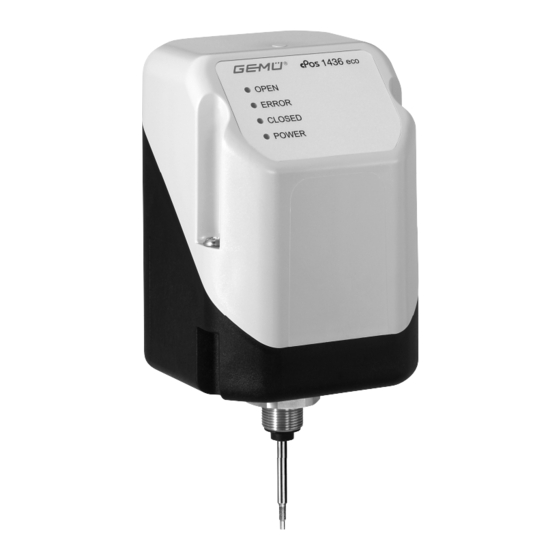
- Page 1 1436 cPos eco Intelligenter Stellungsregler für fremdgesteuerte Linearantriebe Intelligent Positioner for pneumatically operated linear actuators ORIGINAL QUICK GUIDE QUICK GUIDE Stand 01.06.16 Status 01st June 2016 1436 cPos eco...
-
Page 2: Table Of Contents
Hinweise 2. Druckfeder über Spindel schieben. Hinweise zur Sicherheit Die Sicherheitshinweise entnehmen Sie 3. Spindel an Punkt a fixieren bitte der Bedienungsanleitung des GEMÜ (Spindel darf dabei nicht beschädigt 1436 cPos eco. werden). Sollten Sie nicht im Besitz dieser Bedienungsanleitung sein, wenden Sie sich bitte an GEMÜ. -
Page 3: Komplettierung Des Weggebers
Stellungsregler 1 an geeigneter Stelle befestigen. Ventil mit Stellungsregler Hierzu kann der Befestigungs- Weggeber komplettieren (siehe Kapitel winkel GEMÜ 1446 00 ZMP 2.1.2 „Komplettierung des Weggebers“). verwendet werden (dieser Stellungsregler 1 auf Antrieb 3 muss separat bestellt werden). aufsetzen und mit einem geeigneten Weggeber komplettieren (siehe Kapitel Gabelschlüssel SW27 am Weggeber 2... -
Page 4: Anbau An Schwenkantriebe
Die Welle des Weggebers ist mit einer Markierung 7 versehen. Stimmt diese Markierung mit der Markierung auf der Unterseite des Weggebergehäuses 8 überein, so befi ndet sich der Weggeber in der 0° Stellung. Weggeber mit Markierung 1436 cPos eco 4 / 20... -
Page 5: Anbau Des Stellungsreglers
Ventil mit externem Weggeber Stellungsregler 1 an geeigneter Stelle befestigen. Hierzu kann der Befestigungs- Ventil mit Stellungsregler winkel GEMÜ 1446 00 ZMP Weggeber komplettieren (siehe Kapitel verwendet werden (dieser 2.2.2 „Komplettierung des Weggebers“). muss separat bestellt werden). Stellungsregler 1 mit Adapter 9 und Weggeber komplettieren (siehe Kapitel Haltewinkel 6 auf Antrieb 3 aufsetzen. -
Page 6: Pneumatische Anschlüsse
Uv, 24 V DC Versorgungsspannung Arbeitsanschluss für I+, 4...20 mA Sollwerteingang Prozessventil (Steuer- G 1/8 funktion 1 und 2) Uv, I-, GND M12-Stecker I+, 4...20 mA Stellungsrückmeldung A-Kodierung Uv, Initialisierung 24 V DC, Auslösung der Initialisierung mittels Impulssignal 1436 cPos eco 6 / 20... -
Page 7: Variante Mit Externem Weggeber (Code S01)
A-Kodierung Versorgungsspannung (-) n.c. n.c. Initialisierung und Inbetriebnahme Wird der GEMÜ 1436 cPos eco ab Werk komplett an ein Ventil montiert geliefert, so ist dieser schon werkseitig voreingestellt (bei einem Steuerdruck von 3. Versorgungsspannung 24 V einschalten 5,5 - 6 bar ohne Betriebsdruck) (siehe Kapitel 4 "Elektrische Anschlüsse"). -
Page 8: Automatische Initialisierung
(t > 100 ms). Externer Anbau an Linearantrieb Symbol Symbol OPEN CLOSED ERROR POWER +24V DC 2. Initialisierungsspannung deaktivieren. Symbol Symbol Externer Anbau an Schwenkantrieb OPEN CLOSED ERROR POWER +24V DC 1436 cPos eco 8 / 20... -
Page 9: Gefahr
OPEN CLOSED Im Zweifelsfall oder bei Missverständnissen ist die deutsche Version des Dokuments ERROR POWER ausschlaggebend! +4-20mA ® Nach Beenden der Initialisierung wird das Prozessventil in die Position gemäß Sollwertsignal positioniert. Sollwert min Symbol Symbol OPEN CLOSED ERROR POWER Sollwert max... - Page 10 2. Push the spring over the spindle. Safety notes Please refer to the safety notes included 3. Fix the spindle at point a in the GEMÜ 1436 cPos eco operating (the spindle must not be damaged instructions. during this process).
-
Page 11: Assembling The Travel Sensor
(only for version with remote mounting) g) Valve with external travel sensor Fix the positioner 1 at a suitable location. The mounting bracket GEMÜ 1446 00 ZMP can be used Valve with positioner for this purpose (it must be ordered separately). -
Page 12: Mounting To Quarter Turn Actuators
The travel sensor shaft 7 is marked. If this marking corresponds with the marking at the bottom of the travel sensor housing 8, the travel sensor is in the 0° position. Travel sensor with marking 1436 cPos eco 12 / 20... -
Page 13: Mounting The Positioner
(only for version with remote mounting) Valve with external travel sensor Fix the positioner 1 at a suitable location. The mounting bracket GEMÜ 1446 00 ZMP can be used Valve with positioner for this purpose (it must be Assemble the travel sensor (see chapter ordered separately). -
Page 14: Pneumatic Connections
Uv, I-, GND M12 plug Working connection A coding I+, 4...20 mA (feedback signal) for process valve G 1/8 (control function 1 Uv, Initialization 24 V DC starting and 2) the initialization via digital input 1436 cPos eco 14 / 20... -
Page 15: Version With External Actual Value
(-) n.c. n.c. Initialisation and commissioning 3. Switch on the 24V DC power supply (see If the GEMÜ 1436 cPos eco is delivered fully mounted to chapter 4 "Electrical connections"). a valve ex works, it is already Symbol Symbol... - Page 16 24 V DC on pin 5 (t > 100 ms). Remote mounting to linear actuators Symbol Symbol OPEN CLOSED ERROR POWER +24V DC 2. Deactivate initialisation power supply. Symbol Symbol Remote mounting to quarter turn actuators OPEN CLOSED ERROR POWER +24V DC 1436 cPos eco 16 / 20...
-
Page 17: Danger
Commissioning for damages caused by improper handling or third-party actions. Exhaust air and cycle duties In case of doubt contact GEMÜ generate noise! before commissioning. ® Hearing damage. DANGER Wear hearing protection. Note on staff training:... - Page 18 1436 cPos eco 18 / 20...
- Page 19 1436 cPos eco 19 / 20...
- Page 20 GEMÜ Gebr. Müller Apparatebau GmbH & Co. KG · Fritz-Müller-Str. 6-8 · D-74653 Ingelfi ngen-Criesbach Telefon +49(0)7940/123-0 · Telefax +49(0)7940/123-192 · info@gemue.de · www.gemu-group.com...
Need help?
Do you have a question about the 1436 cPos eco and is the answer not in the manual?
Questions and answers