GEM 4242 Operating Instructions Manual
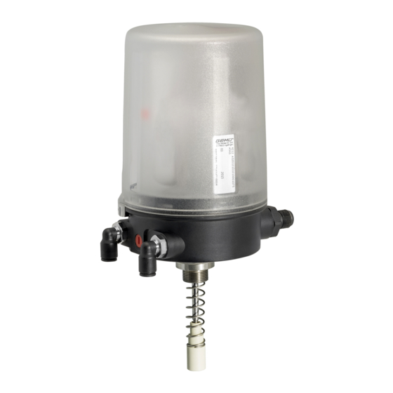
Combi switchbox with integrated pilot valve
Hide thumbs
Also See for 4242:
- Operating instructions manual (36 pages) ,
- Operating instructions manual (40 pages) ,
- Operating instructions manual (51 pages)

Related Manuals for GEM 4242


Summary of Contents for GEM 4242
- Page 1 GEMÜ 4242 Combi switchbox with integrated pilot valve Operating instructions further information webcode: GW-4242...
- Page 2 All rights including copyrights or industrial property rights are expressly reserved. Keep the document for future reference. © GEMÜ Gebr. Müller Apparatebau GmbH & Co. KG 20.12.2021 GEMÜ 4242 2 / 46 www.gemu-group.com...
-
Page 3: Table Of Contents
17 Manual override ........... Function ............18 Troubleshooting ..........Product label ..........18.1 LED error message ........4 GEMÜ CONEXO ............ 18.2 Troubleshooting ..........5 Correct use ............19 Inspection and maintenance ........ 6 Order data ............20 Disassembly ............ -
Page 4: General Information
NOTICE friendly commissioning function for fast mounting, automated Potentially dangerous situation! setting and initialization of GEMÜ products. Dependent on type, activation uses an external impulse signal or existing ▶ Non-observance can cause damage to precautions on the device (magnetic or housing switch). -
Page 5: Safety Information
13. Maintain the product correctly. 14. Do not carry out any maintenance work and repairs not de- scribed in this document without consulting the manufac- turer first. In cases of uncertainty: 15. Consult the nearest GEMÜ sales office. www.gemu-group.com 5 / 46 GEMÜ 4242... -
Page 6: Led Displays
A2, A3, Communica- tion error/ad- dress 0 Flashes red Device error PWR/FAULT Green SIO operation (IO-Link ver- Flashes green Communica- sion, code tion active IOL) Communica- tion error or supply voltage too low GEMÜ 4242 6 / 46 www.gemu-group.com... -
Page 7: Description
3.5 Product label The GEMÜ 4242 with integrated pilot valve is designed for pneumatic actuators. The product has a microprocessor-con- Device version Design in accordance with order data trolled intelligent position sensor as well as an analogue travel sensor system (potentiometer). - Page 8 3. Warning label "Danger from electrostatic build-up". 4. Warning label "Do not disconnect when live". The housing must be installed protected from mechanical in- fluences. RFID chips must not be read out in potentially explosive areas. GEMÜ 4242 8 / 46 www.gemu-group.com...
-
Page 9: Order Data
6 mm angled connection Air supply 6 mm T-connection, exhaust air 6 mm angled connection Connection thread M5 for size 1, connection thread G1/8 for size 2 (for IP67 or piped air outlet) www.gemu-group.com 9 / 46 GEMÜ 4242... - Page 10 Connection thread M5 for size 1, connection thread G1/8 for size 2 8 Option Manual override 9 Flow rate 14 Nl/min, size 1 10 Travel sensor version Potentiometer 30 mm length, size 1 11 Special version Without GEMÜ 4242 10 / 46 www.gemu-group.com...
-
Page 11: Technical Data
EN 61000-6-2 IO-Link Interference emission EN 61000-6-3 Interference resistance EN 61000-6-2 AS-Interface Interference emission acc. to AS-Interface Spec. 3.0 Interference resistance acc. to AS-Interface Spec. 3.0 DeviceNet Interference emission EN 61000-6-3 Interference resistance EN 61000-6-2 www.gemu-group.com 11 / 46 GEMÜ 4242... - Page 12 075: IO-Link face certificate specification V No. 125601 SIL: Product description: GEMÜ electrical position indicator 4242 Device type: Valid software version: V1.1.X.X Safety function: The fail-safe state is defined as a High (24 V DC) signal at pin 4 (device version 24 V IO-Link), if the current posi- tion of the integrated travel sensor is smaller than the switch point CLOSED (default setting 12%).
- Page 13 Min. switch point OPEN 0.5 mm 1.25 mm 0.5 mm If the percentage switch points dependent on the programmed stroke are smaller than the permiss- ible min. switch points, the min. switch points apply automatically. www.gemu-group.com 13 / 46 GEMÜ 4242...
-
Page 14: Dimensions
WAF 24 for mounting kit M16x1, WAF 24 for mounting kit M16x1, x = 11 mm x = 11 mm Potentiometer, 75 mm length Potentiometer, 30 mm length dependent on valve used dependent on valve used Dimensions in mm GEMÜ 4242 14 / 46 www.gemu-group.com... -
Page 15: Manufacturer's Information
2. Avoid UV rays and direct sunlight. 3. Do not exceed the maximum storage temperature (see chapter "Technical data"). 4. Do not store solvents, chemicals, acids, fuels or similar fluids in the same room as GEMÜ products and their spare parts. 10 Assembly and installation NOTICE Pay attention to the information on product labels, in ●... -
Page 16: Mounting The Combi Switchbox On Linear Actuators
NOTICE ▶ For some valves (e.g. GEMÜ 650 and GEMÜ 687) it is ne- 1. Move the actuator to the closed position. cessary to fit a pressure disc between the threaded ad- 2. - Page 17 6. Connect the product pneumatically (see “Pneumatic con- nection“, page 19). 7. Initialize the product (see “Commissioning“, page 22). CAUTION Incorrect installation of the product. ▶ Damage to the housing. Only tighten the product using the spanner flats provided ● for this purpose. www.gemu-group.com 17 / 46 GEMÜ 4242...
-
Page 18: Mounting The Combi Switchbox On Quarter Turn Actuators
3. Turn the housing clockwise to align the pneumatic or elec- trical connections. 4. Connect the product electrically (see “Electrical connec- tion“, page 20). 5. Connect the product pneumatically (see “Pneumatic con- nection“, page 19). 6. Initialize the product (see “Commissioning“, page 22). GEMÜ 4242 18 / 46 www.gemu-group.com... -
Page 19: Pneumatic Connection
1) only relevant for exhaust air duct and/or increase of protection tion size class Air supply connection G 1/8 Working connection for process G 1/8 valve Venting connection with silencer (in- G 1/8 tegrated housing ventilation) www.gemu-group.com 19 / 46 GEMÜ 4242... -
Page 20: Electrical Connection
Sensor error, pneumatic error, programming error, internal er- 1. Connect the product in accordance with the pin assign- ment. 12.3.2 Inputs (pin 5, 6) For electrical connection, we recommend the M12 connectors for EX areas from IFM, series EVCxxA. Input impedance GEMÜ 4242 20 / 46 www.gemu-group.com... -
Page 21: Io-Link, Ordering Option Fieldbus, Code Iol
Signal name ment. U, 24 V DC, supply voltage n.c. U, GND C/Q IO-Link 12.5 AS-Interface, ordering option Fieldbus, code A2, A3, A4 Observe the safety information and general information in the "Electrical connection" section. www.gemu-group.com 21 / 46 GEMÜ 4242... -
Page 22: Devicenet, Ordering Option Fieldbus, Code Dn
6. Connect the product pneumatically to the process valve. 7. Connect the pneumatic tubes and activate the pneumatic control air supply of max. 7 or 9 bar. 8. Carry out initialisation on-site or via communication inter- face. GEMÜ 4242 22 / 46 www.gemu-group.com... - Page 23 ð The OPEN, CLOSED and high visibility LEDs light up de- 10. Close valve until end position is reached. pending on the product (see “LED displays“, page 6). 11. Set DO2 = 0. (The product is in normal operation) www.gemu-group.com 23 / 46 GEMÜ 4242...
- Page 24 9. Set DO2 = 0. (The product is in normal operation) ð The end positions are set. ð The OPEN, CLOSED and high visibility LEDs light up de- pending on the product (see “LED displays“, page 6). GEMÜ 4242 24 / 46 www.gemu-group.com...
-
Page 25: Specific Data - Io-Link
38400 baud Frame type in Operate: Min. cycle time: 2.3 ms Vendor-ID: Device-ID: 424201 Product-ID: 4242 IO-LINK ISDU support: SIO operation: IO-Link specification: Size 1 Size 2 V1.1 V1.1 when using IODD 1.1 1) When using IODD 1.0.1 the device works in accordance with IO-Link specification V1.0 (compatibility mode) Note for IO-Link: IODD files can be downloaded via the hyperlinks https://ioddfinder.io-link.com/... -
Page 26: Parameter Overview
Setting options [Hex] bindex rights 0x10 Vendor Name 6 byte StringT GEMUE 0x12 Product Name 13 byte StringT 4242 IO-Link 0x13 Product ID 8 byte StringT 4242 IO-LINK 0x15 Serial number 9 byte StringT 0–4294967296 0x16 Hardware Revision 8 byte StringT Rev. -
Page 27: Description Of Parameter Values
Inversion of feedback signals Inversion of optical and electrical feedback for OPEN/CLOSED feedback. Travel sensor position Feedback Standard Inversed Travel sensor retracted (valve spindle is OPEN CLOSED Travel sensor extended (valve spindle is CLOSED OPEN down) www.gemu-group.com 27 / 46 GEMÜ 4242... - Page 28 Value actually used for the switch point for OPEN feedback. Threshold closed request Corresponds to "Threshold open request" but for CLOSED feedback. Threshold closed real Corresponds to "Threshold open real" but for CLOSED feedback. GEMÜ 4242 28 / 46 www.gemu-group.com...
- Page 29 The delay time before the warning occurs corresponds to the time of parameter Alarm closing time. NOTICE ▶ If the parameter Alarm closing time is deactivated (setting 0), the alarm Stroke reduction is deactivated. Alarm opening time Delay time for pneumatic error OPEN. www.gemu-group.com 29 / 46 GEMÜ 4242...
- Page 30 A switching cycle is valid if the valve travels from one defined end position to the other defined end position and returns to the original end position. If an end position is not reached, the switching cycle is not valid and is not counted. Counter Powerfail Power failure counter. Counter Power on Power on counter. GEMÜ 4242 30 / 46 www.gemu-group.com...
- Page 31 Counter Sensor error closed Sensor error counter/CLOSED position. Counter over temperature Overtemperature counter. Reset to default Reset to default settings. Reset travel sensor Reset travel sensor calibration. Actual AD-value Current value of AD converter. www.gemu-group.com 31 / 46 GEMÜ 4242...
-
Page 32: Events
1 = process valve in CLOSED position Indication of operating mode 0 = normal operation 1 = programming mode Error 2 see error analysis Error 3 Error 4 DI6, not used Error 1 see error analysis GEMÜ 4242 32 / 46 www.gemu-group.com... -
Page 33: Outputs
0 = standard 1 = inversed Location function 0 = deactivated 1 = activated On-site programming 0 = enabled 1 = disabled 1) Activation of outlet 4, only for double acting function (code 02) www.gemu-group.com 33 / 46 GEMÜ 4242... -
Page 34: Switch Point Parameters
Ordering option Fieldbus A3, A4 Parameter Switch point OPEN [%] Switch point CLOSED [%] *P0 and P1 are not used Switch points: The data in percent refer to the programmed stroke, before each end position GEMÜ 4242 34 / 46 www.gemu-group.com... -
Page 35: Error Analysis
Status Device status according to DeviceNet specifications Series No. Continuous serial number Name 4242 DN combi switchbox 1) Use EDS file in accordance with revision status of the device Note: Download EDS files from www.gemu-group.com www.gemu-group.com 35 / 46 GEMÜ 4242... -
Page 36: Net Topology - Devicenet System
0 = warning not active 1 = warning active Global errors General error 0 = error not active 1 = error active As seen from the DeviceNet master, Class 64h, Inst. 1h, Attr. 1h GEMÜ 4242 36 / 46 www.gemu-group.com... -
Page 37: Outputs
1 = automatic programming mode active not used As seen from the DeviceNet master, Class 64h, Inst. 1h, Attr. 1h 1) Activation of outlet 4, only for double acting function (code 02) www.gemu-group.com 37 / 46 GEMÜ 4242... -
Page 38: Parameter Overview
Display of numerical val- tion OPEN 0–4092 Programmed posi- 2 byte UINT tion CLOSED Programmed stroke 2 byte UINT Last position OPEN 2 byte UINT Last position 2 byte UINT CLOSED Last stroke 2 byte UINT GEMÜ 4242 38 / 46 www.gemu-group.com... - Page 39 3 = Stroke reduction posi- tion closed + open Get/Set Valve cycles user 4 byte UDINT Resettable to 0, display of numerical values 0–429496729 Valve cycles total 4 byte UDINT Display of numerical val- 0–429496729 www.gemu-group.com 39 / 46 GEMÜ 4242...
-
Page 40: Manual Override
(see "Technical cess valve is in the data") valid sensor range. Sensor error Sensor limit ex- Check the mount- CLOSED or OPEN ceeded ing kit, re-pro- position gramme. Note the maximum stroke (see "Technical data") GEMÜ 4242 40 / 46 www.gemu-group.com... -
Page 41: Inspection And Maintenance
CLOSED pos- Check the correct No spare parts are available for this product. If it is faulty, ition exhaust air duct please return it to GEMÜ for repair. (see "Pneumatic connections") 19.2 Cleaning the product Check the process... -
Page 42: Disassembly
Returned goods can be processed only when this note is completed. If no return delivery note is included with the product, GEMÜ cannot process credits or repair work but will dispose of the goods at the operator's expense. -
Page 43: Declaration Of Incorporation According To 2006/42/Ec (Machinery Directive)
23 Declaration of Incorporation according to 2006/42/EC (Machinery Directive) 23 Declaration of Incorporation according to 2006/42/EC (Machinery Directive) www.gemu-group.com 43 / 46 GEMÜ 4242... -
Page 44: Declaration Of Conformity According To 2014/30/Eu (Emc Directive)
24 Declaration of conformity according to 2014/30/EU (EMC Directive) 24 Declaration of conformity according to 2014/30/EU (EMC Directive) GEMÜ 4242 44 / 46 www.gemu-group.com... -
Page 45: Declaration Of Conformity In Accordance With 2014/34/Eu (Atex)
25 Declaration of Conformity in accordance with 2014/34/EU (ATEX) 25 Declaration of Conformity in accordance with 2014/34/EU (ATEX) www.gemu-group.com 45 / 46 GEMÜ 4242... - Page 46 GEMÜ Gebr. Müller Apparatebau GmbH & Co. KG Fritz-Müller-Straße 6-8, 74653 Ingelfingen-Criesbach, Germany Subject to alteration Phone +49 (0) 7940 1230 · info@gemue.de www.gemu-group.com 12.2021 | 88792712...
Need help?
Do you have a question about the 4242 and is the answer not in the manual?
Questions and answers