Table of Contents
Advertisement
Quick Links
Advertisement
Table of Contents

Related Manuals for Pilz PSEN cs5.13 M12/8


Summary of Contents for Pilz PSEN cs5.13 M12/8
- Page 1 PSEN cs5.13 M12/8 EX Operating Manual-22218-EN-07 - PSEN sensor technology...
- Page 2 We do assure you that all persons are regarded without discrim- ination and on an equal basis. All rights to this documentation are reserved by Pilz GmbH & Co. KG. Copies may be made for the user's internal purposes. Suggestions and comments for improving this documenta- tion will be gratefully received.
-
Page 3: Table Of Contents
Periodic test ..........................30 Adjustment ..........................30 Operation ..........................31 Normal mode..........................31 Error display ..........................32 Dimensions in mm .........................33 Technical details ........................34 Safety characteristic data......................37 Supplementary data .......................38 Radio approval ..........................38 Order reference ........................38 System ............................38 Operating Manual PSEN cs5.13 M12/8 EX 22218-EN-07... - Page 4 Contents Accessories..........................38 EC declaration of conformity ....................41 UKCA-Declaration of Conformity ..................41 Operating Manual PSEN cs5.13 M12/8 EX 22218-EN-07...
-
Page 5: Introduction
PSEN cs5.13 M12/8 EX Introduction Validity of documentation This documentation is valid for the product PSEN cs5.13 M12/8 EX from Version 2.0. This operating manual explains the function and operation, describes the installation and provides guidelines on how to connect the product. -
Page 6: Safety
Any component, technical or electrical modification to the product, Use of the product outside the areas described in this operating manual, Use of the product outside the technical details (see chapter entitled Technical Details [ 34]). Operating Manual PSEN cs5.13 M12/8 EX 22218-EN-07... -
Page 7: Safety Regulations
– PSEN Y junction M12 sensor – PSEN Y junction M12 cable You will need to be conversant with the information in these documents in order to fully un- derstand this operating manual. Operating Manual PSEN cs5.13 M12/8 EX 22218-EN-07... -
Page 8: Use Of Qualified Personnel
– If substitute actuators are used, these must be installed as described under Installation [ 27]. – If the original actuators are replaced with substitute actuators, the ori- ginal actuators must be destroyed before disposal. Operating Manual PSEN cs5.13 M12/8 EX 22218-EN-07... -
Page 9: Unit Features
Diagnostic input for Y1 for Safety Device Diagnostics (SDD) Signal output/diagnostic output Y32 for Safety Device Diagnostics LED display for: – State of actuator detection – State of the inputs – Supply voltage/fault Operating Manual PSEN cs5.13 M12/8 EX 22218-EN-07... -
Page 10: Function Description
If an SDD fieldbus module is used, the diagnostic input Y1 is automatically activated and data is read. If no SDD fieldbus module is used, the diagnostic input Y1 is not used. Operating Manual PSEN cs5.13 M12/8 EX | 10 22218-EN-07... -
Page 11: Safety Device Diagnostics
– Information is passed on via the fieldbus module directly to the network – Mappings of the signal outputs to the sensor are automated by the SDD. Operating Manual PSEN cs5.13 M12/8 EX | 11 22218-EN-07... -
Page 12: Operating Distances
Typical release distance: 14 mm [2] Actuator aligned to the triangle marking on the switch Assured operating distance: 4 mm Assured release distance: 12 mm Typical operating distance: 5 mm Typical release distance: 8 mm Operating Manual PSEN cs5.13 M12/8 EX | 12 22218-EN-07... - Page 13 PSEN cs5.13 M12/8 EX [3] Actuator aligned to the semicircle marking on the switch Assured operating distance: 3 mm Assured release distance: 16 mm Typical operating distance: 6 mm Typical release distance: 8 mm Operating Manual PSEN cs5.13 M12/8 EX | 13 22218-EN-07...
-
Page 14: Lateral And Vertical Offset
-12 -8 -4 0 Legend [1] Hysteresis [2] Typical operating distance S [3] Typical release distance S [4] Offset in mm [5] Operating distance in mm [6] Response range [7] Status of LED Operating Manual PSEN cs5.13 M12/8 EX | 14 22218-EN-07... - Page 15 [2] Typical operating distance S [3] Typical release distance S [4] Offset in mm [5] Operating distance in mm [6] Response range [7] Status of LED [8] Square marking [9] Triangle marking Operating Manual PSEN cs5.13 M12/8 EX | 15 22218-EN-07...
- Page 16 [8] Limit of response range, position of gate hinge [9] Status of LED [10] Sensing face of the actuator, labelled with Pilz logo [11] Distance from the front edge of the safety switch to the limit of the response range (position of the gate end stop) = 15.9 mm...
- Page 17 8 4 0 8 4 0 Legend [1] Hysteresis [2] Typical operating distance S [3] Typical release distance S [4] Offset in mm [5] Operating distance in mm [6] Response range Operating Manual PSEN cs5.13 M12/8 EX | 17 22218-EN-07...
-
Page 18: Wiring
60 VDC. The power supply must meet the regulations for extra low voltages with protective elec- trical separation (SELV, PELV). Information given in the Technical details [ must be followed. Operating Manual PSEN cs5.13 M12/8 EX | 18 22218-EN-07... - Page 19 As shown in the diagram, combine the clips supplied above the screw connection of the cable and press both parts firmly onto each other. The clips must audibly lock into posi- tion and they must not be manually detachable. Legend [1] Manipulation protection CABLE/M12/CLIP Operating Manual PSEN cs5.13 M12/8 EX | 19 22218-EN-07...
-
Page 20: Connection To Evaluation Devices
0 V UB blue Diagnostics input The wire colour also applies for the cable available from Pilz as an accessory. NOTICE The inputs S11 and S21 may only be used for the series connection with Pilz sensors. Connection to evaluation devices... - Page 21 Evaluation device FS: Fail-Safe 24 V Connection diagram, single connection with SDD Safety switch Actuator area I1 (FS) I2 (FS) Non- Evaluation device area FS: Failsafe Fieldbus module 24 V 0 V Operating Manual PSEN cs5.13 M12/8 EX | 21 22218-EN-07...
- Page 22 – PSEN ix2 F4 code – PSEN ix2 F8 code – PSEN Y junction M8-M12/M12 PIGTAIL – PSEN Y junction M12-M12/M12 PIGTAIL – PSEN Y junction M12 SENSOR – PSEN Y junction M12 cable channel Operating Manual PSEN cs5.13 M12/8 EX | 22 22218-EN-07...
- Page 23 PSEN cs5.13 M12/8 EX Connection diagram, series connection without SDD Controller Safety switch Actuator Safety switch Actuator Safety switch Actuator Ex area I1 (FS) I2 (FS) Non-Ex area Evaluation device FS: Fail-Safe 24 V Operating Manual PSEN cs5.13 M12/8 EX | 23 22218-EN-07...
- Page 24 Connection diagram, series connection with SDD Actuator Safety switch Actuator Safety switch Actuator Safety switch Ex area I1 (FS) I2 (FS) Non-Ex area Evaluation device FS: Failsafe Fieldbus module 24 V Operating Manual PSEN cs5.13 M12/8 EX | 24 22218-EN-07...
- Page 25 The connections to two evaluation devices are shown on the following pages, by way of ex- ample: PNOZ s3 and PNOZmulti The safety switch PSEN cs5.13 M12/8 EX can be connected to Pilz evaluation devices, for example. Suitable Pilz evaluation devices are, for example: PNOZelog for safety gate monitoring...
-
Page 26: Teaching In The Actuator
Fieldbus module PNOZmulti PSENcode Without SDD With SDD Teaching in the actuator Any approved Pilz actuator (see Intended use) is detected as soon as it is brought into the response range. Operating Manual PSEN cs5.13 M12/8 EX | 26 22218-EN-07... -
Page 27: Installation
Torque setting: Please note the information provided under Technical details [ 34]. The distance between two safety switches must be maintained (see Technical details [ 34]). The distance can be undershot in certain application cases (see diagrams). Operating Manual PSEN cs5.13 M12/8 EX | 27 22218-EN-07... - Page 28 Close the mounting holes using the seals provided (see diagrams). The use of seals should be regarded as equivalent to using permanent fastenings in accordance with EN ISO 14119. Fig.: Seals [1]: 4 seals for actuators [2]: 2 seals for actuators [3]: 2 seals for actuators Operating Manual PSEN cs5.13 M12/8 EX | 28 22218-EN-07...
- Page 29 Operating Manual PSEN cs5.13 M12/8 EX | 29 22218-EN-07...
-
Page 30: Periodic Test
Operating distances may deviate if other arrangements are used. Note the maximum permitted lateral and vertical offset (see Operating distances [ Lateral and vertical offset [ 14]). Operating Manual PSEN cs5.13 M12/8 EX | 30 22218-EN-07... -
Page 31: Operation
Ready for operation Green Safety Gate Actuator is within the response range yellow Actuator is outside the response range Input Both safety inputs are high yellow Both safety inputs are low Operating Manual PSEN cs5.13 M12/8 EX | 31 22218-EN-07... -
Page 32: Error Display
Display not Wrong actuator Only use an appropriate definitive actuator from Pilz. Yellow Green Switch doesn't start Change the switch. Yellow Yellow Operating Manual PSEN cs5.13 M12/8 EX | 32 22218-EN-07... -
Page 33: Dimensions In Mm
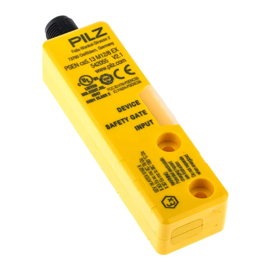
PSEN cs5.13 M12/8 EX Dimensions in mm Safety switch DEVICE SAFETY GATE INPUT 26,4 Actuator Legend: [1] Square marking [2] Triangle marking [3] LEDs [4] Semicircle marking Operating Manual PSEN cs5.13 M12/8 EX | 33 22218-EN-07... -
Page 34: Technical Details
Voltage drop at OSSDs Conditional rated short circuit current 100 A Lowest operating current 2 mA Utilisation category in accordance with EN 60947-1 DC-12 Times Max. test pulse duration, safety outputs 150 µs Operating Manual PSEN cs5.13 M12/8 EX | 34 22218-EN-07... - Page 35 1 mm Shock stress in accordance with the standard EN 60947-5-2 Acceleration Duration 11 ms Airgap creepage Overvoltage category Pollution degree Rated insulation voltage 75 V Rated impulse withstand voltage 1 kV Operating Manual PSEN cs5.13 M12/8 EX | 35 22218-EN-07...
- Page 36 Max. fixing screws torque settings 1 Nm Dimensions Height 26,4 mm Width 101,6 mm Depth 19 mm Actuator dimensions Height 18 mm Width 37 mm Depth 19 mm Weight of safety switch 68 g Operating Manual PSEN cs5.13 M12/8 EX | 36 22218-EN-07...
-
Page 37: Safety Characteristic Data
A safety function's SIL/PL values are not identical to the SIL/PL values of the units that are used and may be different. We recommend that you use the PAScal software tool to calculate the safety function's SIL/PL values. Operating Manual PSEN cs5.13 M12/8 EX | 37 22218-EN-07... -
Page 38: Supplementary Data
2) this product must accept any interference received, including interference that may cause undesired operation. Changes or modifications made to this product not expressly approved by Pilz may void the FCC authorization to operate this equipment. NOTE: This equipment has been tested and found to comply with the limits for a Class A digital device, pursuant to Part 15 of the FCC Rules. - Page 39 PSEN Y junction M8-M12/ M12, 8-pin, socket M12, 8‑pin, pin 540337 M12 PIGTAIL 8‑pin, socket PSEN Y junction M12-M12/ M12, 8-pin, socket M12, 8‑pin, pin M12, 8- 540338 M12 PIGTAIL pin, socket Operating Manual PSEN cs5.13 M12/8 EX | 39 22218-EN-07...
- Page 40 Safety Device Dia- gnostics SDD ES Profibus Profibus fieldbus module Spring-loaded terminal 540132 for Safety Device Dia- gnostics SDD ES Profinet Profinet fieldbus module for Spring-loaded terminal 540138 Safety Device Diagnostics Operating Manual PSEN cs5.13 M12/8 EX | 40 22218-EN-07...
- Page 41 European Parliament and of the Council. 2006/42/EC on machines 2014/34/EU (ATEX) 2014/53/EU on radio equipment The complete EC Declaration of Conformity is available on the Internet at www.pilz.com/ downloads. Representative: Pilz GmbH & Co. KG, Felix-Wankel-Str. 2, 73760 Ostfildern, Germany UKCA-Declaration of Conformity...
- Page 42 We are represented internationally. Please refer to our homepage www.pilz.com for further details or contact our headquarters. Headquarters: Pilz GmbH & Co. KG, Felix-Wankel-Straße 2, 73760 Ostfildern, Germany Telephone: +49 711 3409-0, Telefax: +49 711 3409-133, E-Mail: info@pilz.com, Internet: www.pilz.com...
Need help?
Do you have a question about the PSEN cs5.13 M12/8 and is the answer not in the manual?
Questions and answers