
Subscribe to Our Youtube Channel
Related Manuals for Sinoboom TB32JN Plus


Summary of Contents for Sinoboom TB32JN Plus
- Page 1 Maintenance Part No.505071110002 Rev: C Manual Nov. 2022 产品说明书 PRODU C T MAN U AL TB32JN Plus/TB1060JN Plus 0608E (2132E) G T JZ 0808E (2732E) G T JZ 0808E (2732E) G T JZ G T JZ 0808E (2732E)
- Page 3 Operating, servicing and maintaining this vehicle or equipment can expose you to chemicals including engine exhaust, carbon monoxide, phthalates, and lead, which are known to the State of California to cause cancer and birth defects or other reproductive harm. To minimize exposure, avoid breathing exhaust, do not idle the engine except as necessary, service your vehicle or equipment in a well-ventilated area and wear gloves or wash your...
- Page 4 : No.128, East Jinzhou Avenue, Ningxiang High-tech Industrial Park, Changsha, Hunan, China Zip Code : 410600 Copyright © Hunan Sinoboom Intelligent Equipment Co., Ltd. All Rights Reserved The final interpretation right of this manual belongs to Hunan Sinoboom Intelligent Equipment Co., Ltd.
- Page 5 (See Decals/Nameplate Inspection of the Operation Manual for details.) Trade Identification Model Serial No. Imperial Metric From 0507100166 to present TB32JN Plus TB32JN Plus TB1060JN Plus NOTE: • Product model is applied in product nameplate for distinction of products of different main parameters.
- Page 6 This Page Intentionally Left Blank...
- Page 7 This manual covers the basic parts information of one or more products. Therefore, please use this manual according to your needs. If you find problems in the manual or have suggestions for improve- ment, feel free to share your feedback with Sinoboom, and we will address these issues as soon as possible.
- Page 8 This Page Intentionally Left Blank...
-
Page 9: Table Of Contents
Hydraulic System ..... 3-1 Pins and composite bearing... 4-5 TB32JN Plus Maintenance Manual © Nov. 2022... - Page 10 B-5 Replace Fuel Strainer (fuel- Checklist D Procedures ....5-35 water separator) Element ..5-19 © Nov. 2022 TB32JN Plus Maintenance Manual...
- Page 11 Electrical Symbols ....6-36 Electrical Schematic ....6-38 7 Control system ....7-1 TB32JN Plus Maintenance Manual © Nov. 2022...
- Page 12 © Nov. 2022 TB32JN Plus Maintenance Manual...
-
Page 13: Introduction
The owner or administrator of the machine shall also provide the manufacturer’s maintenance information to the person responsible for maintaining the machine. If you have any questions, contact Hunan Sinoboom In- telligent Equipment Co., Ltd.. TB32JN Plus Maintenance Manual © Nov. 2022... - Page 14 This Page Intentionally Left Blank © Nov. 2022 TB32JN Plus Maintenance Manual...
-
Page 15: Safety
In case of any accident involving the machinery of Also, people who have alcohol or drugs in their Hunan Sinoboom Intelligent Equipment Co., Ltd., notify system, or experience excessive fatigue or Hunan Sinoboom Intelligent Equipment Co., Ltd. -
Page 16: Electrocution Hazards
Table 1-1 Minimum Safe Distance Voltage Minimum Safe Distance (Phase to Phase, kV) (m/ft) 0-50 3.05 (10) 50-200 4.60 (15) 200-350 6.10 (20) 350 -500 7.62 (25) 500 -750 10.67 (35) 750 -1000 13.725 (45) © Nov. 2022 TB32JN Plus Maintenance Manual... - Page 17 Do not use the platform or boom uneven surfaces, or near holes assembly to push other machines and steep slopes, maintain a or objects. minimum distance of 0.6m (2ft) and reduce the speed. TB32JN Plus Maintenance Manual © Nov. 2022...
-
Page 18: Jobsite Hazards
Do not lift the platform when the wind speed exceeds 12.5 m/s (28 mph). If the wind speed exceeds 12.5 m/s (28 mph) after the platform is lifted, © Nov. 2022 TB32JN Plus Maintenance Manual... - Page 19 If the machine is to be used in any other applications, or by any other means, other than fold the platform and do not those specified by Sinoboom, it must be approved or continue to operate the machine. guided by the manufacturer.
-
Page 20: Unsafe Operation Hazards
The battery not only provides power, but also serves as a counterweight. The battery is vital to maintaining the stability of the machine. © Nov. 2022 TB32JN Plus Maintenance Manual... -
Page 21: Fall Hazards
At a minimum, operators must operate and maintain the machine as stated in the operation manual and in the maintenance manual in addition to following more stringent industry regulations and workplace rules. TB32JN Plus Maintenance Manual © Nov. 2022... -
Page 22: Crush Hazards
Set up roadblocks if necessary. • Limit the speed of travel according to ground conditions, crowding, gradients, the presence and location of personnel and any © Nov. 2022 TB32JN Plus Maintenance Manual... -
Page 23: Explosion And Fire Hazards
During operation, keep the left and right doors of the chassis closed and locked. Only trained service personnel can open the left and right doors to repair the machine. TB32JN Plus Maintenance Manual © Nov. 2022... -
Page 24: Battery Hazards
ELECTROCUTION HAZARD • Contact with hot circuit may cause serious injury or death. Be sure to wear goggles, gloves and protective clothing. • Remove all rings, watches and other accessories. © Nov. 2022 1-10 TB32JN Plus Maintenance Manual... - Page 25 • Do not tamper with battery system to avoid serious accident. • Cut off the battery main switch if the battery is not to be used for an extended period. TB32JN Plus Maintenance Manual 1-11 © Nov. 2022...
-
Page 26: Hydraulic Hazards
OFF position. 7. Turn the key switch at the ground controls to OFF position and remove the key to avoid unauthorized operation of the machine. 8. Turn off the main power switch. © Nov. 2022 1-12 TB32JN Plus Maintenance Manual... - Page 27 SAFETY NOTICE After using the machine, the main power switch must be disconnected. TB32JN Plus Maintenance Manual 1-13 © Nov. 2022...
- Page 28 SAFETY This Page Intentionally Left Blank © Nov. 2022 1-14 TB32JN Plus Maintenance Manual...
-
Page 29: Specifications
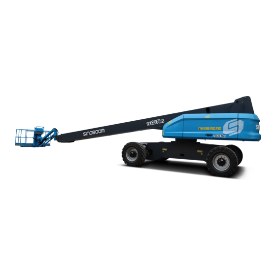
SPECIFICATIONS MACHINE SPECIFICATIONS Table 2-1 TB32JN Plus specifications TB32JN Plus (METRIC) TB1060JN Plus (IMPERIAL) MEASURE DIMENSION Max platform height 32.3m 105ft 12in Max working height 34.3m 112ft 6in Max horizontal reach (restricted/ 17.9m/20.0m 58ft 8in/65ft 7in unrestricted) Max horizontal working envelope 18.5m/20.6m... - Page 30 Max allowable RH Stored at -20℃ to 50℃ (-4℉ to 122℉) in a well-ventilated environment with Storage environment 90% relative humidity (20℃ [68℉]), and away from rain, sun, corrosive gas, inflammables and explosives. WEIGHT © Nov. 2022 TB32JN Plus Maintenance Manual...
- Page 31 The total vibration value of the platform does not exceed 2.5m/s², and the maximum root-mean-square value of the weighted acceleration of the entire machine does not exceed 0.5m/s². TB32JN Plus Maintenance Manual © Nov. 2022...
- Page 32 SPECIFICATIONS Range of motion (5°) 300 kg (661 lb) 454 kg (1001 lb) © Nov. 2022 TB32JN Plus Maintenance Manual...
-
Page 33: Engine Specifications
Displacement 0.77 gal (US) Number of Compression Cylinders 17:1 Ratio 98mm (3.86 in) Bore Firing Order 1-2-4-3 105mm (4.13 in) Stroke Output 55.4kw@2200rpm Total 3.17L Torque 260Nm (192 ft-lb)@1800rpm Displacement 0.70 gal (UK) TB32JN Plus Maintenance Manual © Nov. 2022... -
Page 34: Function Speed
Test twice. Boom up/down**:With the boom horizontally and fully extended, raise the boom from the horizontal to the hightest and lower from the highest to the horizontal, Test twice. © Nov. 2022 TB32JN Plus Maintenance Manual... -
Page 35: Major Component Weight
1st telescopic boom 1061 2nd telescopic boom 3rd telescopic boom Jib boom assembly Platform Counterweight 4898 10798 Slewing mechanism Main boom telescope cylinder Main boom level cylinder, upper Main boom level cylinder, lower TB32JN Plus Maintenance Manual © Nov. 2022... -
Page 36: Hydraulic System Specifications
Closed-circuit variable pump Displacement 45.9cc/r Max drive pressure 28 MPa (4061 Psi) Open-circuit variable pump Displacement 35 cc/r Max drive pressure 22 MPa (3191 Psi) Travel Motor Type Piston motor Displacement 45 cc/r Function Manifold © Nov. 2022 TB32JN Plus Maintenance Manual... -
Page 37: Hydraulic Hose And Fitting
M42 × 2 240 ± 15 Nm (177 ± 11 ft-lb) M45 × 2 250 ± 16 Nm (184 ± 12 ft-lb) 280 ± 18 Nm(207 ± 13 ft-lb ) M52 × 2 TB32JN Plus Maintenance Manual © Nov. 2022... -
Page 38: Hydraulic Fitting Torque
540 ± 30 Nm (398 ± 22 ft-lb) 420 ± 25 Nm (310 ± 18 ft-lb) M48×2 Hydraulic fittings with British Standard Pipe (BSP) thread) must be torqued to the following specifications. © Nov. 2022 2-10 TB32JN Plus Maintenance Manual... - Page 39 110 ± 8 Nm (81 ± 6 ft-lb) 140 ± 10 Nm (103 ± 7 ft-lb) 1-5/16-12 160 ± 10 Nm (118 ± 7 ft-lb) 210 ± 15 Nm (155 ± 11 ft-lb) TB32JN Plus Maintenance Manual 2-11 © Nov. 2022...
-
Page 40: Hydraulic Hose And Fitting Tight
80 Nm (59 ft-lb) 92 Nm (68 ft-lb) 95 Nm (70 ft-lb) 125 Nm (92 ft-lb) 150 Nm (111 ft-lb) 1.75 100 Nm (74 ft-lb) 130 Nm (96 ft-lb) 155 Nm (114 ft-lb) © Nov. 2022 2-12 TB32JN Plus Maintenance Manual... - Page 41 715 Nm (527 ft-lb) 7/8-9 Unless special torque requirements are listed in this manual or other instructions, torque Unified Thread Standard bolts (label: UNF) to the values listed in the table below. TB32JN Plus Maintenance Manual 2-13 © Nov. 2022...
- Page 42 200 Nm (148 ft-lb) 9/16-18 13/16" 200 Nm (148 ft-lb) 280 Nm (207 ft-lb) 5/8-18 15/16" 350 Nm (258 ft-lb) 495 Nm (365 ft-lb) 3/4-16 1-1/8" 560 Nm (413 ft-lb) 780 Nm (575 ft-lb) 7/8-14 © Nov. 2022 2-14 TB32JN Plus Maintenance Manual...
-
Page 43: System Descriptions
The batteries are charged by the DC generator of the engine. Power- off switches are used to protect the control system. TB32JN Plus Maintenance Manual © Nov. 2022... - Page 44 SYSTEM DESCRIPTIONS This Page Intentionally Left Blank © Nov. 2022 TB32JN Plus Maintenance Manual...
-
Page 45: Service And Guidelines
Reference the Repair & Inspection Report for items Qualified Sinoboom equipment mechanic is a person requiring inspection. Reference the Inspection recognized by Sinoboom as one who, by possession of Procedures in appropriate areas of this manual to a recognized degree, certificate, training, has perform the inspection and maintenance procedures. -
Page 46: Preventive Maintenance
SERVICE AND GUIDELINES annual machine inspection, notify Hunan Sinoboom Intelligent Equipment Co., Ltd. of the current machine ownership information. PREVENTIVE MAINTENANCE The preventive maintenance must be performed by a qualified Sinoboom equipment mechanic. Reference the Repair & Inspection Report and Maintenance Schedule in this manual for the inspection items and intervals. -
Page 47: Storage
Never attempt to move heavy parts without the aid of a this manual. mechanical device. Do not allow heavy objects to rest in an unstable position. When raising a portion of the equipment, ensure that adequate support is provided. TB32JN Plus Maintenance Manual © Nov. 2022... -
Page 48: Cleanliness
• The static and dynamic load tests of the machine suggest a compliance with the relevant standard. © Nov. 2022 TB32JN Plus Maintenance Manual... -
Page 49: Pressure-Fit Parts
2. Unless specific torque requirements are given • Excessive sloppiness in joints. within the text, standard torque values should be used on heat-treated bolts, studs, and steel nuts, in • Noise originating from the joint during operation. TB32JN Plus Maintenance Manual © Nov. 2022... -
Page 50: Application Of Insulating Silicone Grease To Electrical Connections
1. Prior to the machine assembling, apply silicone grease around the male pins and female pins inside the connectors to prevent oxidization. An injector may be used for the convenience of operation. © Nov. 2022 TB32JN Plus Maintenance Manual... -
Page 51: Maintenance
& counterbalance valve on the cylinder. inspection report. • Immediately remove a damaged or malfunctioning machine from service, mark and stop using it. TB32JN Plus Maintenance Manual © Nov. 2022... -
Page 52: Conducting A Pre-Delivery Inspection
Every half a year or every 500 involved. Use the table to help you adhere to a routine A+B+C hours maintenance schedule. Every year or every 1000 hours A+B+C+D © Nov. 2022 TB32JN Plus Maintenance Manual... -
Page 53: Completing A Repair & Inspection
A-9 Inspect Coolant Level (water-cooled engine) A-10 Inspect Engine Belt A-11 Inspect Fuel Strainer (fuel-water separator) A-12 Inspect Cooling Fan A-13 Inspect Engine Intake System A-14 Functional Tests A-15 Perform Maintenance after 30 Days TB32JN Plus Maintenance Manual © Nov. 2022... - Page 54 Reducer Oil Level B-13 Inspect Slewing Bearing Bolts B-14 Lubricate Slewing Bearing B-15 Inspect Platform Rotate Cylinder Fasteners B-16 Test Cylinder Drift B-17 Inspect Counterbalance Valve Locking B-18 Inspect Electrical Wiring B-19 Inspect the Battery © Nov. 2022 TB32JN Plus Maintenance Manual...
- Page 55 Reducer Gear Oil D-3 Replace Hydraulic Oil D-4 Replace Hydraulic Tank Suction Filter D-5 Replace Coolant and Coolant Hoses (water-cooled engine) D-6 Replace Fuel Hoses D-7 Inspect Boom Wear Pads User Inspector Signature TB32JN Plus Maintenance Manual © Nov. 2022...
-
Page 56: Major Modification And Repair Record
“Good” condition before company. continuing to use the machine. Table 5-4 Major Modification and Repair Record Model Serial No. Machine Repair- Repairman’s Status Problem Description Modification/Repair Item Date Company and Signature Position ter Change © Nov. 2022 TB32JN Plus Maintenance Manual... -
Page 57: Checklist Aprocedures
Alarms and lighting (if equipped) each use. • Platform(including rails, floor plate, safety lock, Note: If the manuals need to be replaced, please brackets and entry door) contact Hunan Sinoboom Intelligent Equipment Co., Ltd.. • Personal protection equipment • Emergency control equipment A-2 Inspect All Decals •... -
Page 58: Inspect Hydraulic Leakage
Different hydraulic oils can be added according to customer requirements upon factory delivery, but cannot be mixed. Figure 5-2 2. OR turn the Ground/Platform control select switch at the ground controller to the platform control © Nov. 2022 TB32JN Plus Maintenance Manual... -
Page 59: Inspect Fuel Leakage
A-7 Inspect Fuel Leakage Inspecting fuel leakage is vital to safe and normal machine operation. If a fuel leak is not discovered and TB32JN Plus Maintenance Manual © Nov. 2022... -
Page 60: Inspect Engine Oil Level
1. Turn the ground/platform select switch to ground control. 2. Pull out the emergency stop button at ground controller to ON position. © Nov. 2022 5-10 TB32JN Plus Maintenance Manual... -
Page 61: Inspect Coolant Level(Water
Shut off the engine before inspection. Inspect the engine belt for: Figure 5-4 • Crack or breakage 3. The coolant level should be at the fill inlet of the • Wear or misalignment coolant box. • Peeling-off TB32JN Plus Maintenance Manual 5-11 © Nov. 2022... -
Page 62: Inspect Fuel Strainer
• Ensure that a conforming fire extinguisher is readily accessible when performing this inspection procedure. 1. Open the right turntable cover. 2. Locate the fuel strainer. © Nov. 2022 5-12 TB32JN Plus Maintenance Manual... -
Page 63: Water Separator
Be sure to keep the intake system clean and free of leakage. A-14 Functional Tests Figure 5-11 Checking the functions of the machine is vital to safe machine operation. If any function works improperly, it TB32JN Plus Maintenance Manual 5-13 © Nov. 2022... - Page 64 18. Glow plug switch (if equipped) 10. Turntable rotate switch 3. OFF position 11. Main boom telescope switch 19. Ground/Platform select switch 12. Jib up/down switch 20. Emergency stop button 4. Horn button © Nov. 2022 5-14 TB32JN Plus Maintenance Manual...
- Page 65 19. Chassis tilt alarm 32. Platform height 8. Turntable info 20. Platform tilt alarm 21. Heavy load indicator 9. Platform info 33. Overload limit 10. Alarm message 34. Drive limit (operating position) 22. Overload alarm TB32JN Plus Maintenance Manual 5-15 © Nov. 2022...
- Page 66 28. Malfunction indicator panel 6. Main boom lift direction (if equipped) 29. Power indicator light 7. Not used 18. Steer direction 8. Platform rotate switch 19. Drive/steer control handle 30. Horn button © Nov. 2022 5-16 TB32JN Plus Maintenance Manual...
-
Page 67: Perform Maintenance After
4. Repeat the steps 2 and 3 until the oscillate cylinders on both sides have been successfully exhausted. 5. Inspect the counterbalance valve locking. Figure 5-15 TB32JN Plus Maintenance Manual 5-17 © Nov. 2022... -
Page 68: Return Filter Element
Rubber worn to the wear mark. 2. Inspect the lug nuts are torqued to specificion Be cautious of the heated parts of (700Nm[517ft-lb]). engine. Bodily contact with them may result in severe burn. © Nov. 2022 5-18 TB32JN Plus Maintenance Manual... -
Page 69: Replace Fuel Strainer
Figure 5-17 Deutz TD2011L04i fuel • Ensure that a conforming fire strainer extinguisher is readily accessible when performing this inspection procedure. 1. Open the right side cover of turntable. 2. Locate the fuel strainer (fuel-water separator). TB32JN Plus Maintenance Manual 5-19 © Nov. 2022... -
Page 70: Water Separator) Element
Replacing high-pressure filter element on a regular basis is vital to proper machine operation and 9. Clean up the spilled fuel. extending service life. A dirty or blocked filter could cause the machine to work improperly, and continued © Nov. 2022 5-20 TB32JN Plus Maintenance Manual... -
Page 71: Replace Air Filter Element Of
4. Replace the filter element as needed. 5. Clean up the hydraulic oil spills. 6. Start the machine from the ground controller. Figure 5-24 Deutz TD2011L04i air filter 7. Inspect the high-pressure filter and relevant components for leakage. TB32JN Plus Maintenance Manual 5-21 © Nov. 2022... -
Page 72: Sensors
Using the main boom telescope switch, retract the boom. The boom can be fully retracted. Figure 5-27 YUCHAI YCF3050 air filter 3. Loosen the clip at the end cap of air filter, and remove the end cap. © Nov. 2022 5-22 TB32JN Plus Maintenance Manual... -
Page 73: System
3. Inpsect whether the muffler shows signs of heating fatigue or possiblity of interal malfunction. 4. Inspect the catalytic converter for blockage. 5. Tighten or replace parts, if needed, to ensure the exhaust system is free of leakage. TB32JN Plus Maintenance Manual 5-23 © Nov. 2022... -
Page 74: Inspect Drive Reducer Oil
Level Inappropriate gear oil level of slewing reducers will reduce the machine performance, and continued use could result in component damage. Figure 5-30 Inspecting the connecting bolts between chassis and slewing bearing © Nov. 2022 5-24 TB32JN Plus Maintenance Manual... - Page 75 Fig 5-29 , page 5-24, insert a 0.04mm feeler gauge in between the bolt and washer. 4. Ensure the feeler gauge won’t go through the outside of bolt head to the bolt shank. TB32JN Plus Maintenance Manual 5-25 © Nov. 2022...
-
Page 76: Lubricate Slewing Bearing
Maximum Allowable Drift in Fasteners Diameter 10 Minutes (mm/in) (mm/in) Regularly inspecting the platform rotate cylinder fasteners is vital to proper and safe machine operation. 63/2.48 0.96/0.037 80/3.15 0.63/0.025 100/3.94 0.39/0.015 125/4.92 0.23/0.009 © Nov. 2022 5-26 TB32JN Plus Maintenance Manual... -
Page 77: Test Counterbalance Valve
8. The assistant on the ground should inspect whether the wheel on the front left or rear right still remains off the ground, and keept it elevated. TB32JN Plus Maintenance Manual 5-27 © Nov. 2022... -
Page 78: Test Oscillate Outriggers
120mm cables from corrosion. (4.7 in). The instructions below are applied only for batteries 4. The other 3 wheels of the machine should come in requiring maintenance: close contact with the ground. © Nov. 2022 5-28 TB32JN Plus Maintenance Manual... -
Page 79: Test Drive Speed
5. The tilt alarm should sound with the chassis tilt indicator light flashing, some functions are restricted, but the boom retracting, turntable rotating and boom lowering when retracted to less than 1.2m (3ft 11in) should be allowed. TB32JN Plus Maintenance Manual 5-29 © Nov. 2022... -
Page 80: Test Braking Distance
Result: the braking distance is 0.8m (2.62 ft)~1.2m (3.94 ft). NOTICE The brake must be able to hold the machine on any slope it is able to climb. Figure 5-35 Deutz TD2.9 L4 fuel filter © Nov. 2022 5-30 TB32JN Plus Maintenance Manual... -
Page 81: Inspect Boom Extend/Retract
• Manually guide the cables and inspect the cable tension, a properly tensioned cable should be Figure 5-38 WEICHAI WP3.2 fuel filter impossible or hard to be moved. TB32JN Plus Maintenance Manual 5-31 © Nov. 2022... -
Page 82: Replace Engine Oil
4. Move the engine start switch to idle for 2 minutes. 5. Shut off the engine. 6. Open the drain valve to drain the engine oil. Figure 5-42 Cummins QSF2.8t3TC72 engine oil drain valve © Nov. 2022 5-32 TB32JN Plus Maintenance Manual... -
Page 83: Replace Engine Oil Filter
The waste engine oil should be collected in a suitable vessel for disposal or recycling. The Figure 5-46 Deutz TD2011L04i engine oil waste engine oil should be treated in compliance with the environment laws or regulations. filter TB32JN Plus Maintenance Manual 5-33 © Nov. 2022... -
Page 84: Tank
Figure 5-48 WEICHAI WP3.2 engine oil filter Before the test, fully raise and lower the boom and fully extend and retract the boom at least twice to ensure the pulley and track are adequately lubricated. © Nov. 2022 5-34 TB32JN Plus Maintenance Manual... -
Page 85: Checklist Dprocedures
Before conducting any override operation, please make sure the surrounding area and the whole machine are in a safe state, try to avoid operation in a dangerous direction and ensure personal safety. TB32JN Plus Maintenance Manual 5-35 © Nov. 2022... -
Page 86: Replace Hydraulic Oil
6. Remove the fill plug (for the location, reference 12 Inspect Slewing Reducer Oil Level, page 5- 24), add new gear oil to the fill port until the oil level is even with the bottom of the fill plug. © Nov. 2022 5-36 TB32JN Plus Maintenance Manual... -
Page 87: Replace Hydraulic Tank
10. Clean up the coolant spills in performing the procedure. 11. Start the engine from the ground controller to circulate the coolant in the cooling system. Figure 5-52 12. Shut off the engine. TB32JN Plus Maintenance Manual 5-37 © Nov. 2022... -
Page 88: Replace Fuel Hoses
1. Open the right side cover of turntable. damage and unsafe operating conditions. 2. Disconnect and plug the fuel hoses between fuel tank and fuel strainer (fuel-water separator) . 10 10 14 4 2 1 3 3 © Nov. 2022 5-38 TB32JN Plus Maintenance Manual... - Page 89 3mm(0.118in.), the wear pad assembly should be timely replaced. NOTICE The wear pad disassembled from the boom should never be reused. Be sure to replace with a new wear pad asssembly. TB32JN Plus Maintenance Manual 5-39 © Nov. 2022...
- Page 90 MAINTENANCE This Page Intentionally Left Blank © Nov. 2022 5-40 TB32JN Plus Maintenance Manual...
-
Page 91: Repair Procedures
The retract cable is installed outside the boom so that the failures with retract cable are self- TB32JN Plus Maintenance Manual © Nov. 2022... -
Page 92: Platform Controller
5. Use a suitable device to support the platform rotate motor. 6. Remove the bolts and nuts securing the pivot pin 4# to the platform rotate motor. 7. Remove the platform rotate motor. © Nov. 2022 TB32JN Plus Maintenance Manual... -
Page 93: Jib Boom Assembly
3. Lower the boom until the platform sits on the support. Take special care not to press the total Inspecting the jib boom assembly weight of boom over the support. TB32JN Plus Maintenance Manual © Nov. 2022... -
Page 94: Cable Track Assembly
5. Using the lifting device, slowly move the cable track away from the boom. Steel Cable Tensioning Adjustment Figure 6-6 1. Position the boom to horiztontal and extend 1.5– 1.8m(5ft-6ft). 2. Remove the lock nuts from the wire rope retainer. © Nov. 2022 TB32JN Plus Maintenance Manual... - Page 95 6. Using a tool, hold the thread end (turntable end) of the extend cable to prevent it from rotating. 7. Using a wrench, torque alternately the adjusting nuts of the 4 extend cables to 112 Nm(82.68 ft- lb). TB32JN Plus Maintenance Manual © Nov. 2022...
-
Page 96: Main Boom Assembly
When installing hoses and fittings, tighten them according to the specified torque. See Hydraulic Hose and Fitting Specifica- tions, page 2-9. Figure 6-11 © Nov. 2022 TB32JN Plus Maintenance Manual... -
Page 97: Chassis And Turntable Components
For the part number of a specific machine model, please reference the Part Manual. If the replacement tires are not as Hunan Sinoboom Intelligent Equipment Co., Ltd. TB32JN Plus Maintenance Manual © Nov. 2022... -
Page 98: Reducer And Drive Motor
2. Tighten the nuts in the sequence as shown below. Figure 6-13 3. The tightening of the nuts should be done in stages. Following the recommended sequence, tighten nuts per wheel torque as listed in the table below. © Nov. 2022 TB32JN Plus Maintenance Manual... - Page 99 REPAIR PROCEDURES Reducer Assembly Figure 6-15 TB32JN Plus Maintenance Manual © Nov. 2022...
- Page 100 Cylindrical Roller Bearing 79913011 Locknut 79911183 Bearing Support 18125437 Circlip for Hole 79912186 Inner Gear Ring 79916156 Sun Gear 79911093 Planet Carrier 79916119 Planet Gear 18121066 Cylindrical Roller Bearing 18125703 Circlip for Shaft © Nov. 2022 6-10 TB32JN Plus Maintenance Manual...
- Page 101 6. Use a suitable lifting device to support the drive torque the bolts after pretightening. reducer. 8. Attach the hrdraulic hoses. 7. Remove the bolts and washers securing the drive reducer to the outrigger, and remove the drive reducer. TB32JN Plus Maintenance Manual 6-11 © Nov. 2022...
-
Page 102: Turntable Slewing Mechanism
Assembly (see Fig 6-19 Second Stage Planetary Gear Set Assembly, page 6-13) Table 6-3 Screw DESCRIPTION Mounting Disc Slewing Buffer Valve Screw Slewing Motor Slewing Reducer Slewing Bearing Figure 6-18 Brake Assembly © Nov. 2022 6-12 TB32JN Plus Maintenance Manual... - Page 103 Brake Housing Figure 6-20 Second Stage Planetary Gear Set Assembly Table 6-7 DESCRIPTION Retainer Ring for Shaft Bearing Second Stage Planet Gear Retainer Ring for Shaft Gasket Second Stage Planet Gear Carrier TB32JN Plus Maintenance Manual 6-13 © Nov. 2022...
- Page 104 Loctite 272 to the bolt, and intall the bolts one by one. 5. Tighten the bolts in the sequence as shown in the figure below. Figure 6-21 © Nov. 2022 6-14 TB32JN Plus Maintenance Manual...
-
Page 105: Engine
2. Tag and disconnect the battery cables. manual introduces part of engine maintenance items, 3. With assitance of a lifting device, remove the please see the following sections for details: battery. • A-6 Inspect Fuel Level TB32JN Plus Maintenance Manual 6-15 © Nov. 2022... -
Page 106: Hydraulic System
When the engine operates, the hydraulic pump diverts Layout of Hydraulic Elements the pressure oil to the boom function manifold, on Figure 6-24 © Nov. 2022 6-16 TB32JN Plus Maintenance Manual... - Page 107 4. Hydraulic tank 10. Power unit 16. Lift counterbalance valve 5. Brake/2–speed control valve 11. Hydraulic rotary coupler 17. Level counterbalance valve 6. Oscillate control valve 12. High-pressure filter 18. Platform duplex valve TB32JN Plus Maintenance Manual 6-17 © Nov. 2022...
-
Page 108: Function Valves
REPAIR PROCEDURES Function Valves 12-2 12-3 14-1 12-1 14-2 Figure 6-26 Boom Function Manifold (PN.202040003176) © Nov. 2022 6-18 TB32JN Plus Maintenance Manual... - Page 109 Limit boom extending pressure 14–2 Relief valve 6-way O-type 8Nm (6ft-lb) Control steer direction gate valve 6-way Solenoid 8Nm (6ft-lb) Control boom telescoping direction valve 10-way Solenoid 15Nm (11ft-lb) Control boom telescoping direction valve TB32JN Plus Maintenance Manual 6-19 © Nov. 2022...
- Page 110 REPAIR PROCEDURES Figure 6-27 Slewing buffer valve (PN.202040003061) Table 6-11 Slewing buffer valve (PN.202040003061) TORQUE NAME FUNCTION Counterbalance 40~45Nm (30~33ft-lb) Maintain a balanced load valve Shuttle valve Switch oil lines © Nov. 2022 6-20 TB32JN Plus Maintenance Manual...
- Page 111 Table 6-12 Brake/2-speed control valve (PN.202040000006) TORQUE NAME FUNCTION Reducing valve 33.9Nm (25ft-lb) Control brake/2-speed pressure Damper 27.1Nm (20ft-lb) Control braking 3–1 Solenoid valve 27.1Nm (20ft-lb) Control high/low speed switching 3–2 Solenoid valve Damper Damper Damper TB32JN Plus Maintenance Manual 6-21 © Nov. 2022...
- Page 112 40Nm (30ft-lb) Solenoid valve Control oscillation 12~15Nm (9~11ft-lb) Shuttle valve Switch oil lines Damper 5Nm (9ft-lb) Damper 5Nm (9ft-lb) Damper 5Nm (9ft-lb) Hydraulic 45~50Nm (33~37ft-lb) Keep fluid flowing in one way controlled valve © Nov. 2022 6-22 TB32JN Plus Maintenance Manual...
- Page 113 Drain low-pressure fluid Flush valve 40~45Nm (30~33ft-lb) Drive pressure control Relief valve 12~15Nm (9~11ft-lb) Shuttle valve Circuit switchover Damper 5Nm (4ft-lb) Damper 5Nm (4ft-lb) 55~65Nm (41~48ft-lb) Keep fluid flowing in one way Check valve TB32JN Plus Maintenance Manual 6-23 © Nov. 2022...
- Page 114 Table 6-15 Platform duplex manifold (PN.202040000329) TORQUE NAME FUNCTION 40~45Nm (30~33ft-lb) Control jib lifting\lowering direction 1–1 Solenoid valve 40~45Nm (30~33ft-lb) Control platform rotation direction 1–2 Solenoid valve Damper 5Nm (9ft-lb) Damper 5Nm (9ft-lb) © Nov. 2022 6-24 TB32JN Plus Maintenance Manual...
- Page 115 FUNCTION Counterbalance 40~45Nm (30~33ft-lb) Maintain a balanced load valve Figure 6-33 Leveling counterbalance valve (PN.202040000011) Table 6-17 Leveling counterbalance valve (PN.202040000011) NAME TORQUE FUNCTION Counterbalance 70~75Nm (52~55ft-lb) Maintain a balanced load valve TB32JN Plus Maintenance Manual 6-25 © Nov. 2022...
- Page 116 Counterbalance 41~47Nm (30~35ft-lb) Keep the load balanced valve Figure 6-35 Counterbalance valve (PN.202040003219) Table 6-19 Counterbalance valve (PN.202040003219) TORQUE NAME FUNCTION Counterbalance 70~75Nm (52~55ft-lb) Maintain a balanced load valve Damper 5Nm (4ft-lb) © Nov. 2022 6-26 TB32JN Plus Maintenance Manual...
-
Page 117: Hydraulic Symbols
2018.10.25 32.0000 28.5682 17.4787 46.7096 Check valve 28.5682 46.7096 Emergency power 28.5682 16.0000 34.4087 46.7096 34.4087 32.0000 棕 兰 Hydraulic motor 32.0000 黑 16.0000 28.5682 16.0000 Overflow valve 17.4787 46.7096 34.4087 TB32JN Plus Maintenance Manual 6-27 © Nov. 2022 32.0000... -
Page 118: Hydraulic Schematic
REPAIR PROCEDURES Hydraulic Schematic Figure 6-37 Hydraulic schematic © Nov. 2022 6-28 TB32JN Plus Maintenance Manual... -
Page 119: Electrical System
Check whether the obstacle detection switch Obstacle detection Obstacle detection alarm functions properly alarm Drive controller Drive controller error alarm Check the associated error of drive controller error alarm TB32JN Plus Maintenance Manual 6-29 © Nov. 2022... - Page 120 Check the wiring of platform swing right solenoid solenoid valve fault valve fault valve Platform leveling up Platform leveling up solenoid Check the wiring of platform leveling up solenoid solenoid valve fault valve fault valve © Nov. 2022 6-30 TB32JN Plus Maintenance Manual...
- Page 121 Main boom relative Main boom relative angle Check the wiring of main boom relative angle angle sensor fault sensor fault sensor TB32JN Plus Maintenance Manual 6-31 © Nov. 2022...
- Page 122 (highest-level severity) Electrical circuit #1 of coolant level High-voltage short circuit sensor Electrical circuit #1 of coolant level Low-voltage short circuit sensor Data valid but lower than normal Coolant level (medium-level severity) © Nov. 2022 6-32 TB32JN Plus Maintenance Manual...
- Page 123 SAE J1939 accelerator pedal sensor Update error 3326 system Update error 3613 Coolant level sensor Engine coolant level sensor 3614 Network data error Smart control device or component Engine control calibration module 3697 damaged TB32JN Plus Maintenance Manual 6-33 © Nov. 2022...
-
Page 124: Use And Maintenance Of Battery
10%) or battery out of charge for a long time (not timely charged for 3 days or longer when the battery level less than 10%). © Nov. 2022 6-34 TB32JN Plus Maintenance Manual... - Page 125 The self-discharge process will • Recharge the battery before use after removing it accelerate in warmer temperatures. If storing the from storage. battery in hot temperatures or during hot weather, TB32JN Plus Maintenance Manual 6-35 © Nov. 2022...
-
Page 126: Electrical Symbols
10%). θ Electrical Symbols Table 6-25 Symbol Description Level switch Buzzer Oil temperature θ switch θ θ θ Valve Delay relay θ Two lines connected Power-off switch θ Motor Relay 28.5682 46.7096 © Nov. 2022 6-36 TB32JN Plus Maintenance Manual... - Page 127 Symbol Description Key switch Warning lamp Preheating wire Valve Two lines non- connected 兰 棕 Proximity switch/ 黑 Pressure sensor 28.5682 46.7096 28.5682 兰 棕 黑 Fuel level sensor 46.8000 Horn 28.5682 TB32JN Plus Maintenance Manual 6-37 © Nov. 2022...
-
Page 128: Electrical Schematic
XJ1-17/18 XJ1-1/2 2 3 4 5 XJ1-15/16 OUT_24 L202/203 XJ1-19/20 IN_48 OUT_23 DT19 2/19 XJ1-11/12 IN_49 OUT_26 XJ1-9/10 XJ1-7/8 IN_50 OUT_25 XJ1-5/6 Figure 6-38 Electrical schematic of turntable, Cummins QSF2.8t3TC72/China Tier 3 © Nov. 2022 6-38 TB32JN Plus Maintenance Manual... - Page 129 XJ1-1/2 2 3 4 5 XJ1-15/16 OUT_24 L202/203 XJ1-19/20 IN_48 OUT_23 DT19 2/19 XJ1-11/12 IN_49 OUT_26 XJ1-9/10 XJ1-7/8 IN_50 OUT_25 XJ1-5/6 120Ω Figure 6-39 Electrical schematic of turntable, WEICHAI WP3.2/China Tier 4 TB32JN Plus Maintenance Manual 6-39 © Nov. 2022...
- Page 130 XJ1-17/18 XJ1-1/2 2 3 4 5 XJ1-15/16 OUT_24 L202/203 XJ1-19/20 IN_48 OUT_23 DT19 2/19 XJ1-11/12 IN_49 OUT_26 XJ1-9/10 XJ1-7/8 IN_50 OUT_25 XJ1-5/6 Figure 6-40 Electrical schematic of turntable, Yuchai YCF3050/China stage 4 © Nov. 2022 6-40 TB32JN Plus Maintenance Manual...
- Page 131 V(C)_IN_59 PWM_OUT_38 DT15b V(C)_IN_60 PWM_OUT_39 V(C)_IN_56 PWM_OUT_40 IN_47 OUT_24 H103 L105 L106 IN_48 OUT_23 IN_49 OUT_26 IN_50 OUT_25 H100 HG100 S116 SB100 Figure 6-41 Electrical schematic of platform, Cummins QSF2.8t3TC72/China Tier 3 TB32JN Plus Maintenance Manual 6-41 © Nov. 2022...
- Page 132 DT15b V(C)_IN_60 PWM_OUT_39 V(C)_IN_56 PWM_OUT_40 IN_47 OUT_24 H103 L105 L106 IN_48 OUT_23 IN_49 OUT_26 IN_50 OUT_25 H100 HG100 S116 SB100 Figure 6-42 Electrical schematic of platform, WEICHAI WP3.2, Yuchai YCF3050/China Tier 4 © Nov. 2022 6-42 TB32JN Plus Maintenance Manual...
- Page 133 REPAIR PROCEDURES *B05 (1.0) (1.0) *205 (1.0) 250Ω/5W (10.0) (16.0) 150A (2.5) (70.0) *K44 BAT2 BAT1 P&t Figure 6-43 Electrical schematic of engine, WEICHAI WP3.2/China Tier 4 TB32JN Plus Maintenance Manual 6-43 © Nov. 2022...
- Page 134 REPAIR PROCEDURES *205 (1.0) (1.0) 250Ω/5W (10.0) (2.5) (70.0) 150A (16.0) BAT2 BAT1 t° v° v° Figure 6-44 Electrical schematic of engine, Yuchai YCF3050/China stage 4 © Nov. 2022 6-44 TB32JN Plus Maintenance Manual...
-
Page 135: Control System
Therefore, personnel who qualified personnel who have been professionally have not been professionally trained and authorized trained and authorized by Sinoboom, otherwise the by Sinoboom cannot disassemble their housings, consequences will be at your own risk. otherwise moisture and dust will enter the internal mechanism and normal operation will not be guaranteed. - Page 136 Proportional Valve EAT Info Engine Info Engine Fault Diagnoses Turntable Info Turntable Panel Info Platform Panel Info-Input Platform Panel Info-Output Platform Info Alarm Info Alarm Info Fault Info Figure 7-1 Display interface navigation diagram © Nov. 2022 TB32JN Plus Maintenance Manual...
-
Page 137: Main Interface After Booting
Figure 7-2 Main interface after booting DESCRIPTION OF ICON FUNCTION Table 7-1 Description Description Icon Icon Configuration Left/Right arrow key Increase key Turntable information TB32JN Plus Maintenance Manual © Nov. 2022... -
Page 138: Language Setting
/Press to directly return to the previous menu Up/Down arrow key LANGUAGE SETTING Figure 7-3 CONFIGURATION interface 2. Select Language through , and press 1. Press on the main interface to enter to enter LANGUAGE interface. CONFIGURATION interface. © Nov. 2022 TB32JN Plus Maintenance Manual... -
Page 139: Test-Run Information
3s to complete the calibration (the icon before the selected option is switched from , indicating calibration succeeded, and the corresponding actual value will be changed). TB32JN Plus Maintenance Manual © Nov. 2022... -
Page 140: Weight Calibration
7. If re-calibration is required, press to return to the TEST-RUN INFO interface, then re-enter the WEIGHT CALIBRATION interface, and repeat the previous step. © Nov. 2022 TB32JN Plus Maintenance Manual... -
Page 141: Advanced Setting
CONTROL SYSTEM ADVANCED SETTING Personnel who have not been professionally trained and authorized by Sinoboom are not allowed to modify the advanced setting (including sensor configuration, turntable enable, standardization, proportional configuration, parameter restore/save and reserved setting); otherwise they will be responsible for the consequences. -
Page 142: Standardization
KCS standard ( ) will be displayed in the upper right corner of the main interface. • In D/B mode, driving function and boom actions can be performed at the same time. © Nov. 2022 TB32JN Plus Maintenance Manual... -
Page 143: Proportional Configuration
Minimum current: refers to the starting current of actions, which affects the starting and inching performance of actions. The minimum current should be set to a value that allow the action to just TB32JN Plus Maintenance Manual © Nov. 2022... - Page 144 TB Lift Up Inspect (Up) Condition of fully raising: up limit switch is triggered or the articulated boom is positioned at an angle bigger than the set value. © Nov. 2022 7-10 TB32JN Plus Maintenance Manual...
-
Page 145: Parameter Restore/Save
Notes: All parameters can be adjusted within 0~100. Parameter restore/save 1. On the ADVANCED SETTING interface, select Parameter Restore/Save through , and press to enter PARAMETER RESTORE/SAVE interface. Figure 7-19 PARAMETER RESTORE/SAVE interface TB32JN Plus Maintenance Manual 7-11 © Nov. 2022... -
Page 146: System Information
• The configuration of sensors is subject to the actual machine configuration. Figure 7-20 SYSTEM INFO interface Figure 7-22 SENSOR INFO 1 © Nov. 2022 7-12 TB32JN Plus Maintenance Manual... -
Page 147: Digital Input Information
Figure 7-26 OUTPUT INFO 1 interface the machine meets the requirements. • The configuration of switches is subject to the actual machine configuration. TB32JN Plus Maintenance Manual 7-13 © Nov. 2022... -
Page 148: Proportional Information
EAT INFO interface, and the status indicator light will be on. At this time, it is necessary to contact the engine manufacturer for EAT. Figure 7-29 ENGINE INFO interface © Nov. 2022 7-14 TB32JN Plus Maintenance Manual... - Page 149 Standstill regeneration is requested, but Fast since the driver has ignored the request for a flashi- long time, the standstill regeneration can only be completed through the DEUTZ diagnostic tool. TB32JN Plus Maintenance Manual 7-15 © Nov. 2022...
- Page 150 Regeneration function is being executed NCD is not working NCD indicator light (- Solid Yanmar only) NCD is working Regeneration prohibiting Conditions prohibiting active regeneration do indicator light (Yuchai only) not exist © Nov. 2022 7-16 TB32JN Plus Maintenance Manual...
-
Page 151: Turntable Panel Information
• The configuration of switches on the turntable panel is subject to the actual machine configuration. TB32JN Plus Maintenance Manual 7-17 © Nov. 2022... -
Page 152: Alarm Information
Figure 7-40 FAULT INFO interface 1 Figure 7-38 JOYSTICK INFO interface 3. Press successively to return to the main interface, and power off the machine as required. © Nov. 2022 7-18 TB32JN Plus Maintenance Manual... - Page 153 BMS Fault Code Description for Lithium Battery section in the Maintenance Manual (if the machine is equipped with any lithium battery). 5. Press successively to return to the main interface, and power off the machine as required. TB32JN Plus Maintenance Manual 7-19 © Nov. 2022...
- Page 154 CONTROL SYSTEM This Page Intentionally Left Blank © Nov. 2022 7-20 TB32JN Plus Maintenance Manual...
-
Page 155: Appendix 1: Prepare The Work Record Before Delivery
2. Use the table to record the results. After each section is complete, mark the appropriate box. 3. Record the inspection results. If any inspection result is “NO”, the machine must be stopped, and then re- inspected after repair is completed, and the box marked “REPAIRED” shall be checked. TB32JN Plus Maintenance Manual © Nov. 2022... - Page 156 CONTROL SYSTEM This Page Intentionally Left Blank © Nov. 2022 TB32JN Plus Maintenance Manual...
-
Page 157: Appendix 2: Repair & Inspection Report
A-14 Functional Tests A-15 Perform Maintenance after 30 Days A-16 Perform Oscillate Cylinder Exhausting Checklist B Procedures REPAIRED/ YES/Machine is NO/Machine Has Problem Machine Has Items in Good Damage or Description Been Repaired Condition Malfunction TB32JN Plus Maintenance Manual © Nov. 2022... - Page 158 B-17 Inspect Counterbalance Valve Locking B-18 Inspect Electrical Wiring B-19 Inspect the Battery B-20 Test Oscillate Outriggers B-21 Test Drive Speed B-22 Inspect Emergency Lowering B-23 Inspect Tilt Protection B-24 Test Braking Distance © Nov. 2022 TB32JN Plus Maintenance Manual...
- Page 159 D-3 Replace Hydraulic Oil D-4 Replace Hydraulic Tank Suction Filter D-5 Replace Coolant and Coolant Hoses (water-cooled engine) D-6 Replace Fuel Hoses D-7 Inspect Boom Wear Pads User Inspector Signature Inspection Date Inspector Title TB32JN Plus Maintenance Manual © Nov. 2022...
- Page 160 4. Record the inspection results. If any inspection item is marked as “NO”, the machine must be stopped and re- inspected after repair is completed and the box marked "REPAIRED” shall be checked. Select the appropriate inspection procedure based on the inspection type. © Nov. 2022 TB32JN Plus Maintenance Manual...
-
Page 161: Appendix 3: Major Modification And Repair Record
Modification/Repair” in the form will be “Good” and the machine can be used. If either inspection result is “NO”, the machine must be re-inspected after the repair is completed until the machine is in “Good” condition before continuing to use the machine. TB32JN Plus Maintenance Manual © Nov. 2022... - Page 162 Solution s Alw ays For B et t er A ccess Solution s Always for Better Access Solutions AS/N ZS Hunan Sinoboom Intelligent Equipment Co., Ltd. 长沙市宁乡高新技术产业园区金洲大道东 128 号 No.128, East Jinzhou Avenue, Ningxiang High-tech Industrial Park, Changsha, Hunan, China 市宁乡高新技术产业园区金洲大道东...
Need help?
Do you have a question about the TB32JN Plus and is the answer not in the manual?
Questions and answers