Table of Contents
Advertisement
Quick Links
© Copyright 1998
EVERTZ MICROSYSTEMS LTD.
5288 John Lucas Drive, Burlington, Ontario, Canada, L7L 5Z9
Phone:
905-335-3700
BBS:
905-335-9131
Internet:
Tech Support: eng@evertz.com
Sales: sales@evertz.com
Web Page:
Revision 1.0,July 1998
The material contained in this manual consists of information that is the property of Evertz Microsystems and is
intended solely for the use of purchasers of the 8150 Digital Afterburner. Evertz Microsystems expressly prohibits
the use of this manual for any purpose other than the operation of the 8150.
All rights reserved. No part of this publication may be reproduced without the express written permission of Evertz
Microsystems Ltd.
Copies of this guide can be ordered from your Evertz products dealer or from Evertz
Microsystems.
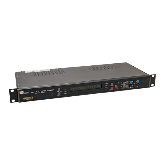
Model 8150
Digital Afterburner
Instruction Manual
Fax:
http://www.evertz.com
905-335-3573
Advertisement
Table of Contents

Related Manuals for evertz 8150


Summary of Contents for evertz 8150
- Page 1 Revision 1.0,July 1998 The material contained in this manual consists of information that is the property of Evertz Microsystems and is intended solely for the use of purchasers of the 8150 Digital Afterburner. Evertz Microsystems expressly prohibits the use of this manual for any purpose other than the operation of the 8150.
- Page 2 WARNING Changes or Modifications not expressly approved by Evertz Microsystems Ltd. could void the user’s authority to operate the equipment. Use of unshielded plugs or cables may cause radiation interference. Properly shielded interface cables with the shield connected to the chassis ground of the device must be used.
- Page 3 Model 8150 Digital Afterburner Manual REVISION HISTORY REVISION DESCRIPTION DATE Original issue July 98...
- Page 4 Model 8150 Digital Afterburner Manual This page left intentionally blank...
-
Page 5: Table Of Contents
1.2. DEFINITIONS ..........................1-2 INSTALLATION........................... 2-1 2.1. REAR PANEL..........................2-1 2.1.1. Digital Video Connections ..................... 2-1 2.1.2. Analog Monitor Connections (8150-MON option) ............2-1 2.1.3. Power Connections ....................... 2-1 2.1.4. Remote Control Connections ..................2-2 2.2. MOUNTING ..........................2-2 2.3. - Page 6 Model 8150 Digital Afterburner Manual 3.5.5. Selecting the Film Related Modes ................3-10 3.6. OPERATING THE 8150 IN 3 LINE VITC MODE............... 3-12 3.6.1. Setting The VITC Reader Line Range - 3 Line VITC Mode ........3-13 3.6.2. Controlling the ‘Look ahead’ Compensation - 3 Line VITC Mode ....... 3-13 3.7.
- Page 7 Figure 2-2: Typical Application of 8150 for Character Generation..........2-4 Figure 3-1: Front Panel Layout ....................3-1 Figure 3-2: Overview of the 8150 Programming Menu System ........... 3-5 Figure 3-3 Overview of the 8150 Engineering Menu ..............3-7 Figure 4-1: DIP Switch Functions ....................4-1 Figure 4-2: Block Diagram ......................
- Page 8 Model 8150 Digital Afterburner Manual This page left intentionally blank TABLE OF CONTENTS...
- Page 9 Model 8150 Digital Afterburner Manual OVERVIEW..........................1-1 1.1. HOW TO USE THIS MANUAL ....................1-2 1.2. DEFINITIONS ..........................1-2...
- Page 10 Model 8150 Digital Afterburner Manual This page left intentionally blank...
-
Page 11: Overview
Most reader settings are automatically detected from the 3 line VITC The Digital Afterburner is designed to work as a companion to the Evertz 4015 and 4025 Film Footage Encoders. Film edge numbers (KeyKode) which have been encoded into the user bits can be recovered and displayed in standard film format notations as are used by the Film Footage Encoder. -
Page 12: How To Use This Manual
Model 8150 Digital Afterburner Manual 1.1. HOW TO USE THIS MANUAL This manual is organized into 4 chapters: Overview, Installation, Operation and Technical Description. Items of special note are indicated with a double box like this. 1.2. DEFINITIONS AES: (Audio Engineering Society): A professional organization that recommends standards for the audio industries. - Page 13 Model 8150 Digital Afterburner Manual CABLE EQUALIZATION: The process of altering the frequency response of a video amplifier to compensate for high frequency losses in coaxial cable. CCIR (International Radio Consultative Committee) An international standards committee. (This organization is now known as ITU.) CCIR-601: (This document now known as ITU-R601).
- Page 14 Model 8150 Digital Afterburner Manual COMPOSITE DIGITAL: A digitally encoded video signal, such as NTSC or PAL video that includes horizontal and vertical synchronizing information. A component digital video recording format that uses data conforming to the CCIR-601 standard. Records on 19 mm magnetic tape.
- Page 15 Model 8150 Digital Afterburner Manual RESOLUTION: The number of bits (four, eight, ten, etc.) determines the resolution of the signal. Eight bits is the minimum resolution for broadcast television signals. 4 bits = a resolution of 1 in 16. 8 bits = a resolution of 1 in 256.
- Page 16 Model 8150 Digital Afterburner Manual This page left intentionally blank OVERVIEW Page 1-6...
-
Page 17: Installation
A BNC output of the optional composite analog encoder. 2.1.3. Power Connections LINE: The 8150 may be set for either 115v/60 Hz or 230v/50 Hz AC operation. The voltage selector switch is accessible on the rear panel. The line voltage connector contains an integral slow blow fuse (and a spare one). -
Page 18: Remote Control Connections
2.2. MOUNTING The 8150 Digital VITC Reader is equipped with rack mounting angles and fits into a standard 19 inch by 1 3/4 inch (483 mm x 45 mm) rack space. The mounting angles may be removed if rack mounting is not desired. -
Page 19: Changing The Fuse
2.4.1. Video Input The 8150 requires that a digital video source be connected to the VIDEO IN SDI video input. The 8150 may be configured to accept either 525 or 625 line digital video in the component (4:2:2) format. The VIDEO TYPE parameter on the front panel menu must be set correctly to match the video input. -
Page 20: Typical Application
EVERTZ MICROSYSTEMS LTD VIDEO FUSE MADE IN CANADA model 8150 115V: PARALLEL VIDEO OUT .25 A SERIAL VIDEO IN 230V: .125 A REMOTE CONTROL 12:45:30:00 DIGITAL VIDEO MONITOR Figure 2-2: Typical Application of 8150 for Character Generation INSTALLATION Page 2-4... -
Page 21: How To Operate The Digital Afterburner
CHAR Figure 3-1: Front Panel Layout The 8150 Digital Afterburner provides a display of time or user bit information from its readers using a 16 digit alphanumeric display on the front panel, or using characters keyed into the input video. Operational control is handled by 16 front panel keys. -
Page 22: Overview Of The Shifted Key Functions
Model 8150 Digital Afterburner Manual Press the CONFIG key again to select another configuration. (See also section 3.9.2) FREEZE Stops the updating of the reader display data on the front panel and in the VCG. A special character ( F ) appears to the left of the numeric display on the front panel, indicating that the display is in Freeze mode. -
Page 23: Status Indicators
Model 8150 Digital Afterburner Manual 3.1.3. Status Indicators There are eight status indicators that show operational status at a glance. VITC Indicates that the data being displayed is from the VITC reader. Indicates that the reader time is properly genlocked to a 625 line component video reference. -
Page 24: Front Panel Drop Frame Indicators (Ntsc Only)
(SELECT, SETUP, !, ", #, $) are used to cycle through the various items on the programming menu. The 8150 menu system consists of a main menu with two or more choices for each menu item. The sub menu items are shown in lower case to allow them to be easily distinguished from the main level items. - Page 25 R1 format 6 dig R1 format 7 dig Figure 3-2: Overview of the 8150 Programming Menu System To enter the front panel programming menu, press the SETUP key. The two vertical arrow keys (#, $) allow you to move vertically within the menu...
-
Page 26: Engineering Setup Menu
This menu should be used by advanced users only, as improper use can overwrite user setups. The 8150 Engineering Setup menu consists of a main menu with two or more choices for each menu item. The sub menu items are shown in lower case to allow them to be easily distinguished from the main level items. -
Page 27: Assigning The Overall Functions Of The Readers
(See section 3.5). Select Rass 3 line mod to configure the Digital Afterburner for reading the 3 Line VITC format. In this mode, the 8150 is configured as a single 3 line OPERATION Page 3-7... -
Page 28: Setting Up The Individual Readers
TYPE and FILM RATE are encoded into the VITC data and are automatically configured when 3 LINE VITC is being read. The Start and End line settings for reader 1 are used to control what lines the 8150 will read in 3 line mod. -
Page 29: Setting The Vitc Reader Line Range
SELECT key. RDR START LINE and RDR END LINE determine a range of lines that the 8150 will look for VITC on. It will attempt to read VITC from the lower number to the higher number. -
Page 30: Selecting The Film Related Modes
1 or reader 2 to recover Film edge numbers that have been encoded by the Evertz Film Footage Encoders model 4015 or 4025. These modes need to be set if the reader 1 or reader 2 mode is set to TIME EDGE or KEYINFO + EDGE. - Page 31 FORMAT menu item. Digits that are not used for footage numbers are utilized for a static prefix number. Select evertz if binary encoding of edge numbers has been used to compress more data into the available space. When EVERTZ style is used, 4, 5, 6 or 7 digits of footage may be selected using the EDGE FORMAT menu item.
-
Page 32: Operating The 8150 In 3 Line Vitc Mode
FILM RATE are encoded into the VITC data and are automatically configured when 3 LINE VITC is being read. When you select any of these menu items while the 8150 is in 3 line mod you will get a message saying Fixed in 3L mode. -
Page 33: Controlling The 'Look Ahead' Compensation - 3 Line Vitc Mode
SELECT key. RDR START LINE and RDR END LINE determine a range of lines that the 8150 will look for VITC on. It will attempt to read VITC from the lower number to the higher number. -
Page 34: Adjusting The Front Panel Display Brightness
Model 8150 Digital Afterburner Manual Select 422 auto for operation with component video with a line rate of either 525 or 625 lines per field. The 8150 will auto detect the line rate and automatically reconfigure itself. Press SHIFT+WINDOW when you are not in the SETUP menus to display the standard that is currently active. -
Page 35: Selecting Whether The Frames, Fields And Symbols Will Be Displayed On The Vcg
Select Vcg symbols on to show the symbols. 3.7.7. Testing the Data Memory The XRAM TEST menu item is used to test the 8150 data memory. XRAM TEST This diagnostic is normally used at factory build time, but may be run at any Xram test on? time if there is suspected memory problems. -
Page 36: Resetting The 8150 To Factory Defaults
If this occurs, contact the factory for further instructions on how to resolve the problem. 3.7.8. Resetting the 8150 to Factory Defaults The FACTORY RESET menu item is used to return the 8150 to its factory FACTORY RESET When you press the ! or " keys, the display shows defaults. -
Page 37: Making Fine Adjustments To The Character Generator Raster Position
Engineering menu. 3.9.1. Storing User Configurations Press CONFIG to enter the configuration mode of the 8150. The front panel shows that you are ready to choose a configuration. Hold the SHIFT key and press one of numeric keys from 1 to 5 to select which configuration will be saved. -
Page 38: Recalling User Configurations
Model 8150 Digital Afterburner Manual 3.9.2. Recalling User Configurations Press CONFIG to enter the configuration mode of the 8150. The front panel shows that you are ready to choose a configuration. Press one of numeric keys from 1 to 5 to select which configuration will be loaded. Press ENTER to load the selected user config. -
Page 39: Technical Description
4.2.1. DIP Switch Functions The main circuit board of the model 8150 contains an 8 position DIP switch that is used to invoke various diagnostic and calibration functions. The functions of each switch are described below. -
Page 40: Circuit Description
(8037) which plugs into the main board via a forty-pin header. The relevant schematic drawings are shown in brackets for each section of the circuit. The heart of the model 8150 circuitry is a programmable logic array (LCA) device (U17) that contains the keyer circuitry and the support circuitry for addressing various devices on the board. -
Page 41: Front Panel Display And Pushbuttons (5220-31)
Model 8150 Digital Afterburner Manual SERIAL MONITOR OUT SERIAL OUT SERIAL PARALLEL PARALLEL SERIAL KEYER VITC RDR/CHAR ANALOG GENERATOR MONITOR MAINS IN SWITCHING POWER SUPPLY DISPLAY Figure 4-2: Block Diagram 4.3.2. Front Panel Display and Pushbuttons (5220-31) A 16 digit alphanumeric display and a 16-button keypad are contained on a separate circuit card (5220) which is connected to the main circuit board via a 20-conductor ribbon cable. -
Page 42: Serial Digital Video Input (8025-33)
Connect a digital voltmeter set on a 10 volt range to the Loop filter test point LF (located at the rear left corner of the 8025 board). Connect a serial digital video signal to the serial input of the 8150. Connect the serial output of the 8150 to a digital monitor, or connect the analog monitor output of the 8150 to an analog monitor. -
Page 43: Serial Digital Video Output (8025-34)
4.3.5. VITC Reader/Character Generator Logic (8037-31, 8037-32, 8037-33) The 8150 is be fitted with an 8037 submodule which contains the VITC reader and character generator logic circuitry. The actual extraction of the VITC and insertion of the character data into the digital bitstream is done by the Keyer LCA circuitry on the main board. -
Page 44: Keyer Lca (8025-32, 8025-35, 8025-37)
4.3.6. Keyer LCA (8025-32, 8025-35, 8025-37) The heart of the 8150 is the Keyer LCA U17 on the main board. Input video from the serial input circuitry is fed to the inputs of the keyer LCA by U7, U8, and U9.
Need help?
Do you have a question about the 8150 and is the answer not in the manual?
Questions and answers