Advertisement
Quick Links
EXE Bandwidth Limiting Script
EXE Connections and Configurations
The following steps should be observed when setting up the EXE.
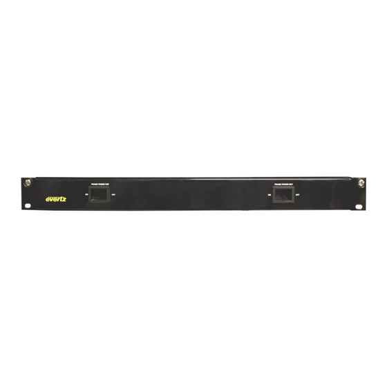
Power Supply Connection:
The power supply comes with an external power switch mounted on a 1RU panel.
There is one switch for the power supplies at the top of the frame and one switch for the supplies at the
bottom of the frame. When the switch is in the Off position all the power modules will be shutdown,
and when the switch is returned to the On position it will cause the power modules to power back up.
Each switch has a mating cable, with four alarm connectors. The alarm connectors are required for the
power tray to current share and therefore must be plugged into the back of each operating power supply
tray.
First, connect an Ethernet cable from the Control Network to the front of the PSU unit. Use a web
browser to open the Power Supply Unit (PSU) web interface, login with username Admin and password
exeadmin. By default each PSU's IP is set to 192.168.0.230.
Date Revised: Jan-12-16
Revision 1.0
Advertisement

Related Manuals for evertz EXE


Summary of Contents for evertz EXE
- Page 1 EXE Bandwidth Limiting Script EXE Connections and Configurations The following steps should be observed when setting up the EXE. Power Supply Connection: The power supply comes with an external power switch mounted on a 1RU panel. There is one switch for the power supplies at the top of the frame and one switch for the supplies at the bottom of the frame.
- Page 2 EXE Bandwidth Limiting Script On the Main page verify that the System Voltage is set to 48V. On the Modules page verify that all Rectifiers in a Shelf have similar current consumptions. Date Revised: Jan-12-16 Revision 1.0...
- Page 3 Connect the NCS’s Control port using a 1GE RJ-45 SFP to a switch or directly to the controlling PC so that the NCS User Interface may be accessed. b. Connect the NCS’s FC CFG A port using a 1GE RJ-45 SFP to EXE-FC A on FC Cfg1 using another 1GE RJ-45 SFP.
- Page 4 EXE Bandwidth Limiting Script b. On EXE-FC , 10GE ports use SFP10G-TR13-A c. On EXE-FC , 1GE ports use SFPTR-RJ45-SER-AV Map of NCS ports to physical ports: Control eth0 FC CFG A eth2 FC CFG B eth3 ...
- Page 5 EXE NCS-A Settings EXE-NCS-A Network Configuration The EXE-NCS-A network can be set from either the Host webpage or command line interface. This step is required if the customer wants to use a different IP address, Netmask or Gateway than the pre-set settings.
- Page 6 Finally reboot the system for the changes to take effect; enter reboot in the NCS host terminal. EXE-NCS-A host will automatically assign an IP address for the Guest by using the Host’s IP + 1. For example: Host IP is 10.10.10.10 Guest IP will be 10.10.10.11 EXE-NCS-A Host 1.
- Page 7 EXE Bandwidth Limiting Script c. Time Server: The IP address of the Time Server being used to synchronize the NCS Host clock with an NTP server. 2. The Second page is the Guest page. The parameters on this page are defined as: a.
- Page 8 1. EXE frame can’t boot There are some reasons that may cause the EXE frame to be unable to boot up properly. The most common reason is because there is no link between the NCS’ and the FC’s. The following steps will describe how to troubleshoot this problem: a.
- Page 9 10GE SFP1 port. 2. Port down There are some reasons that may cause the EXE port to remain Down. a. The Port is set to Down on the Guest Webpage: Go to the Port tab on the Guest webpage, make sure Operation is set to Up.
- Page 10 100..240 optical d. Link is down on the other side (end-device) Ensure the link is UP on other device which is connected to EXE port. e. Bad SFP Go to Port tab on Guest webpage and check “TX power level” and “RX power level”.
Need help?
Do you have a question about the EXE and is the answer not in the manual?
Questions and answers