Table of Contents
Advertisement
Quick Links
© Copyright 2008, 2009
EVERTZ MICROSYSTEMS LTD.
5288 John Lucas Drive,
Burlington, Ontario,
Canada,
L7L 5Z9
Phone:
Sales Fax:
Tech Support Phone:
Version 1.2. June 2009
The material contained in this manual consists of information that is the property of Evertz Microsystems and is intended solely
for the use of purchasers of the EQT Routers. Evertz Microsystems expressly prohibits the use of this manual for any purpose
other than the operation of the Routers.
All rights reserved. No part of this publication may be reproduced without the express written permission of Copies of this
guide can be ordered from your Evertz products dealer or from Evertz Microsystems Ltd. Copies of this guide can be ordered
from your Evertz products dealer or from Evertz Microsystems.
EQT SERIES ROUTERS
SYSTEM MANUAL
+1 905-335-3700
+1 905-335-3573
+1 905-335-7570
Internet:
Sales:
Tech Support: service@evertz.com
Web Page:
sales@evertz.com
http://www.evertz.com
Advertisement
Table of Contents

Related Manuals for evertz EQT Series


Summary of Contents for evertz EQT Series
- Page 1 The material contained in this manual consists of information that is the property of Evertz Microsystems and is intended solely for the use of purchasers of the EQT Routers. Evertz Microsystems expressly prohibits the use of this manual for any purpose other than the operation of the Routers.
- Page 3 IMPORTANT SAFETY INSTRUCTIONS The lightning flash with arrowhead symbol within an equilateral triangle is intended to alert the user to the presence of un-insulated “Dangerous voltage” within the product’s enclosure that may be of sufficient magnitude to constitute a risk of electric shock to persons. The exclamation point within an equilateral triangle is intended to alert the user to the presence of important operating and maintenance (Servicing) instructions in the literature accompanying the product.
- Page 4 WARNING Changes or Modifications not expressly approved by Evertz Microsystems Ltd. could void the user’s authority to operate the equipment. Use of unshielded plugs or cables may cause radiation interference. Properly shielded interface cables with the shield connected to the chassis ground of the device must be used.
- Page 5 Evertz products are for informational use only and are not warranties of future performance, either expressed or implied. The only warranty offered by Evertz in relation to this product is the Evertz standard limited warranty, stated in the sales contract or order confirmation form.
- Page 6 EQT Router User Manual This page left intentionally blank Revision 1.2 Page ii...
-
Page 7: Table Of Contents
EQT Router User Manual TABLE OF CONTENTS 1. OVERVIEW...........................1 1.1. HOW TO USE THIS MANUAL....................3 1.2. DEFINITIONS..........................4 2. INSTALLATION........................7 2.1. UNPACKING..........................7 2.2. PHYSICAL INSTALLATION ..................... 7 2.2.1. Router Frames......................7 2.2.2. Remote Panels ......................7 2.3. ELECTRICAL CONNECTIONS ....................7 2.3.1. - Page 8 EQT Router User Manual 3.1.8. Physical ........................18 3.1.9. Electrical ........................18 4. OPERATION ........................19 4.1. SYSTEM OVERVIEW ......................19 4.1.1. Front View........................20 4.1.2. Rear View ........................21 4.2. SYSTEM CONFIGURATION ....................21 4.2.1. Setting Communication Settings from the Front Panel ..........21 4.2.2.
- Page 9 EQT Router User Manual Figures Figure 1-1: The EQT Signal Processing Router .................. 1 Figure 2-1: EQT Rear View ......................... 7 Figure 2-2: EQT Rear View with Fiber Inputs and Outputs ..............8 Figure 2-3: Example Alarm Circuit..................... 14 Figure 2-4 - EQT-PS Power Supply ....................15 Figure 2-5: PSU Mounting Screw Locations..................
- Page 10 EQT Router User Manual This page left intentionally blank Revision 1.2 Page vi...
-
Page 11: Overview
In order to offer the best in customer support, Evertz supplies the EQT router with a full one-year manufacturing warranty. This guide is intended as an instructional reference for the EQT routing switcher. In the event of further product information or assistance, please contact Evertz or your local Evertz distributor. - Page 12 EQT Router User Manual CONFIGURATION: The EQT is housed in a 2RU frame and switches 32 sources to 32 destinations. Both the input and output stage of the EQT are fixed at 32. CONTROL: The EQT router is compatible with the existing range of Quartz routers, remote control panels and control systems.
-
Page 13: How To Use This Manual
This manual will assist you in the use of the EQT router, and contains all the necessary information to successfully operate this product. If further product information or assistance is required, please contact Evertz or your local Evertz/Quartz distributor. This manual is organized into 6 sections: Overview, Installation, Technical Description, System Control Overview, VistaLINK Remote Monitoring/Control, and Configuration. -
Page 14: Definitions
EQT Router User Manual 1.2. DEFINITIONS The sampling ratio used in the HDTV digital video signal. For every 4 samples of 4:2:2: luminance there are 2 samples each of R-Y (Red minus Luminance) and B-Y (Blue minus Luminance). A wide screen television format such as HDTV in which the aspect ratio of the screen 16x9: is 16 units wide by 9 high as opposed to the 4x3 of normal TV. - Page 15 EQT Router User Manual DROP FRAME: In NTSC systems, where the frame rate is 29.97002618 frames per second, the drop frame mode permits time of day indexing of the frame numbers by dropping certain frame numbers. Specifically frames 0, and 1 at the beginning of each minute except minutes 0,10,20,30,40, &...
- Page 16 EQT Router User Manual SMPTE 272M: The SMPTE standard for embedding audio in serial digital standard definition (SMPTE 259M-C) video signals. SMPTE 274M: The SMPTE standard for bit parallel digital interface for high definition component video signals with an active picture of 1080 lines x 1920 pixels. SMPTE 276M: The SMPTE standard for transmission of AES/EBU Digital Audio Signals Over Coaxial Cable.
-
Page 17: Installation
EQT Router User Manual 2. INSTALLATION 2.1. UNPACKING Remove the equipment carefully from the boxes and check against the Packing List supplied with each unit. This shows what items have been shipped against your order and includes all options. Any error should be reported to your supplier immediately. After you have unpacked the equipment please save all the packing material as this could be useful in the future should the unit need to be returned for maintenance. -
Page 18: Video Inputs And Outputs
EQT Router User Manual 2.3.1. Video Inputs and Outputs These connections are made using standard 75Ω video BNC connectors. There are 32 inputs and 32 outputs on the EQT rear panel. A high quality coax cable such as PSF1/2 (TF3255) for analog video, PSF1/3 (TF3304) for SDI video, Belden 8281 or 1694 for SDI-HD video or suitable equivalents should be used for optimum performance. -
Page 19: Optical Fiber Handling And Care
EQT Router User Manual 2.3.3.1 Optical Fiber Handling and Care The SFP fiber modules are equipped with a class 1 laser and emit invisible radiation. Avoid exposure to the laser emitter and do not stare directly into unconnected SFP emitter ports or fiber ends that are connected to SFP ports. -
Page 20: Removing An Sfp Module
2.3.4.1 Manual Remote Control - Using Q-Link All EQT routers can be connected to other Evertz routers and remote control panels by a single coaxial link called Q-Link. This link uses standard 75Ω video cable daisy-chained from frame to frame and from panel to panel over a maximum cable length of 500m. -
Page 21: Serial Connections
The rear panel of the EQT has two separate DB9 female serial connectors, Serial 1 and Serial 2. The EQT supports Quartz(-1) protocol commands over the serial port. For information regarding the Quartz protocol, contact Evertz service. The pin-out for the serial ports is shown in Table 2-1 below:... -
Page 22: Ethernet Connections
EQT Router User Manual As an option it is possible to convert either of the two serial ports to RS232 with the following pin-out, as shown in Table 2-2. RS232 9 WAY FEMALE D-TYPE SIGNAL Table 2-2: RS-232 Pin out 2.5. -
Page 23: Alarm Connector
EQT Router User Manual Note the following cabling information for this wiring guide: • Only two pairs of wires are used in the 8-pin RJ-45 connector to carry Ethernet signals. • Even though pins 4, 5, 7 and 8 are not used, it is mandatory that they be present in the cable. •... -
Page 24: Reference
EQT Router User Manual Figure 2-3: Example Alarm Circuit 2.7. REFERENCE 2.7.1. Video Reference There must be an analog reference present to ensure the crosspoint changes occur during the field- blanking interval. If the reference is missing then the routing will occur asynchronously. If you experience problems with clean switching then refer to our application note AN-0008. -
Page 25: Power Supply
EQT Router User Manual 2.8. POWER SUPPLY The EQT router power supplies operate on either 100 to 240 volts AC at 50 or 60 Hz and automatically senses the input voltage. Power should be applied by connecting a 3-wire grounding type power supply cord to the power entry module on the rear panel. -
Page 26: Removing The Power Supply
EQT Router User Manual The EQT rear panel is fitted with another LED to monitor the state of the main board. This Green LED is ON when the main board of the router boots up properly and PROC OK: is in operating mode. This LED is OFF when there are issues with the boot up process. -
Page 27: Technical Description
EQT Router User Manual 3. TECHNICAL DESCRIPTION 3.1. SPECIFICATIONS 3.1.1. Configuration Fixed at 32 Inputs: Fixed at 32 Outputs: Redundant Power Supply Redundant Protection: 3.1.2. Video Inputs SMPTE 259M, SMPTE 292M, SMPTE 310M, SMPTE 424M, ASI Standards: 800mV p-p Signal Level: 75Ω... -
Page 28: Fiber Outputs (-F Fiber Version)
EQT Router User Manual 3.1.5. Fiber Outputs (-F Fiber version) Number of Fiber Outputs: 2 270Mb/s, 1.485Gb/s, 2.970Gb/s Reclocked Data Rate: -5dBm Min. Avg Optical Power 1310nm Output Wavelength 10km Max Distance @ 3Gb/s LC/PC Connectors: Single Mode Fiber Type: 3.1.6. -
Page 29: Operation
EQT Router User Manual 4. OPERATION 4.1. SYSTEM OVERVIEW The EQT router is a 32x32 matrix router that provides a simple cost-effective solution for small router applications. The EQT consists of 32 equalized inputs and 32 reclocked outputs. Each input and each output is interfaced through a common crosspoint that is controlled by the main processing unit. -
Page 30: Front View
EQT Router User Manual R e c lo c k e r O p tic a l to E le c t r ic a l to F ib e r ( 2 7 0 M b / s , F ib e r E le c tr ic a l O p tic a l... -
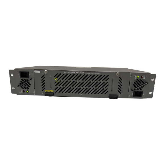
Page 31: Rear View
EQT Router User Manual 4.1.2. Rear View There are a number of communication connections on the rear of the EQT frame. Figure 4-5 and Figure 4-6 identifies all of the connections on the rear panel. These connections provide access to the various communication facilities of the EQT router, such as alarms, control and video status monitoring. -
Page 32: Accessing The Configuration And Monitoring Menu
EQT Router User Manual The following chart provides a brief description of the menus that are accessible through the front panel. Sets the Q-Link address of the device. QLAD Sets the IP address of the device. IPAD Sets the Netmask. NETM Controls the Dynamic Host Configuration Protocol function. -
Page 33: Configuration And Monitoring Menu
EQT Router User Manual 4.2.3. Configuration and Monitoring Menu The following chart provides a brief description of the menus that are accessible through the configuration and monitoring option. Configuration of network settings. Network Configuration Configuration of serial ports. Serial Port Setup Configuration of Simple Network Management Protocol settings. -
Page 34: Setting The Serial Port Setup
EQT Router User Manual 4.2.3.2 Setting the Serial Port Setup The Serial Port Setup menus are used to configure parameters associated with the serial communications of the device. The following chart provides a brief description of the items available in the Serial Port Setup menu. -
Page 35: Setting The Engineering/Debug
EQT Router User Manual 4.2.3.6 Setting the Engineering/Debug The Engineering/Debug menus are used to view and set parameters associated with the frame and video configuration of the device. The following chart provides a brief description of the items available in the Engineering/Debug menu. Configuration of the Q-Link address, inputs, outputs, level, and Q-Link View / Set Frame port. -
Page 36: Signal And System Monitoring
4.4.1. Controlling the EQT Using Ethernet The EQT supports Evertz control panels that have an Ethernet connection. The EQT supports Quartz (-1) protocol commands over the Ethernet port (slave end), therefore, any control device that supports Quartz protocol can control the EQT via Ethernet. -
Page 37: Controlling The Eqt Using Q-Link
4.4.2. Controlling the EQT Using Q-Link The EQT router supports Evertz control panels that have a Q-Link connection. Q-Link control requires the use of a Quartz SC-1000 system controller to translate the control commands from the panels to the EQT and vice versa. -
Page 38: Configuration
EQT Router User Manual 5. CONFIGURATION 5.1. CONFIGURING PANELS FOR USE WITH THE EQT The EQT is able to host up to ten Ethernet control panels without the need for an external control system. All information regarding names is stored on the panels and not the EQT. The following section details the steps required to setup the EQT to communicate with Ethernet control panels. -
Page 39: Figure 5-2: Winsetup Panel Configuration Screen
EQT Router User Manual 3. Sources: Enter the sources dialog and use the Add button to fill the name table with SRC-1 to SRC-32. The names within this table will be the ones used on the panels. Any changes here will be reflected on all of the panels. -
Page 40: Exporting Panel Configurations To Panels
EQT Router User Manual 5.1.2. Exporting Panel Configurations to Panels Once all desired panels have been added, select the Panel button from the main screen in WinSetup and the following prompt will appear as shown in Figure 5-3. Figure 5-3: WinSetup System Panels Screen Select each panel individually and click the FTP Export button. -
Page 41: Vistalink® Remote Monitoring/Control
3. A virtual database, known as the Management Information Base (MIB) lists all the variables being monitored and which both the Manager and Agent understand. Please contact Evertz for further information about obtaining a copy of the MIB for interfacing to a third party Manager/NMS. -
Page 42: Vistalink
EQT Router User Manual 6.2. VISTALINK MONITORED PARAMETERS ® The following parameters can be remotely monitored through the VistaLINK interface. ® Parameter Description Indicates the model of the device. Card Type Indicates the Q-Link address of the device. Q-Link Address Indicates the number of video inputs of the device. -
Page 43: Vistalink Traps
EQT Router User Manual 6.4. VISTALINK TRAPS ® Parameter Description Raises a trap when the router comes online. Become Active Raises a trap when the temperature exceeds ideal conditions. Temperature Warning Raises a trap when the right (when viewed from the front) power Right Power Supply Failure supply fails. - Page 44 EQT Router User Manual This page left intentionally blank Revision 1.2 Page 34 VISTALINK...
Need help?
Do you have a question about the EQT Series and is the answer not in the manual?
Questions and answers