Table of Contents
Advertisement
Quick Links
© Copyright 2008 - 2014
EVERTZ MICROSYSTEMS LTD.
5288 John Lucas Drive,
Burlington, Ontario,
Canada,
L7L 5Z9
Phone:
Sales Fax:
Tech Support Phone:
Version 1.9.1, January 2014
The material contained in this manual consists of information that is the property of Evertz Microsystems and is intended solely
for the use of purchasers of the EQT Routers. Evertz Microsystems expressly prohibits the use of this manual for any purpose
other than the operation of the Routers.
All rights reserved. No part of this publication may be reproduced without the express written permission of Copies of this
guide can be ordered from your Evertz products dealer or from Evertz Microsystems Ltd. Copies of this guide can be ordered
from your Evertz products dealer or from Evertz Microsystems.
EQT SERIES ROUTERS
SYSTEM MANUAL
+1 905-335-3700
+1 905-335-3573
+1 905-335-7570
Internet:
Sales:
Tech Support: service@evertz.com
Web Page:
sales@evertz.com
http://www.evertz.com
Advertisement
Table of Contents

Related Manuals for evertz EQT Series


Summary of Contents for evertz EQT Series
- Page 1 The material contained in this manual consists of information that is the property of Evertz Microsystems and is intended solely for the use of purchasers of the EQT Routers. Evertz Microsystems expressly prohibits the use of this manual for any purpose other than the operation of the Routers.
- Page 2 This page left intentionally blank...
- Page 3 IMPORTANT SAFETY INSTRUCTIONS The lightning flash with arrowhead symbol within an equilateral triangle is intended to alert the user to the presence of un-insulated “Dangerous voltage” within the product’s enclosure that may be of sufficient magnitude to constitute a risk of electric shock to persons. The exclamation point within an equilateral triangle is intended to alert the user to the presence of important operating and maintenance (Servicing) instructions in the literature accompanying the product.
- Page 4 FIBER OPTIC DEVICES Some modules in this product may have fiber optic outputs. The following safety information applies to the optical outputs of these modules. Consult individual chapters for specific safety information for handling fiber optics. WARNING CAUTION – CLASS 1 VISIBLE & INVISIBLE LASER RADIATION WHEN OPEN DO NOT VIEW DIRECTLY OR WITH OPTICAL INSTRUMENTS.
- Page 5 INFORMATION FOR NEBS COMPLIANT VERSIONS The intra-building port(s) of this equipment is suitable for connection to intra-building or unexposed wiring or cabling only. The intra-building port(s) of the equipment MUST NOT be metallically connected to interfaces that connect to the OSP or its wiring. These interfaces are designed for use as intra-building interfaces only (Type 2 or Type 4 ports as described in GR- 1089-CORE, Issue 4) and require isolation from the exposed OSP cabling.
- Page 6 WARNING Changes or Modifications not expressly approved by Evertz Microsystems Ltd. could void the user’s authority to operate the equipment. Use of unshielded plugs or cables may cause radiation interference. Properly shielded interface cables with the shield connected to the chassis ground of the device must be used.
- Page 7 Evertz products are for informational use only and are not warranties of future performance, either expressed or implied. The only warranty offered by Evertz in relation to this product is the Evertz standard limited warranty, stated in the sales contract or order confirmation form.
- Page 8 EQT Router User Manual This page left intentionally blank Page ii Revision 1.9.1...
-
Page 9: Table Of Contents
EQT Router User Manual TABLE OF CONTENTS 1. OVERVIEW ..........................1 1.1. CONFIGURATION ......................2 1.2. CONTROL ......................... 2 1.3. POWER SUPPLY ....................... 2 1.4. TECHNICAL ........................2 1.5. FEATURES (ALL VERSIONS).................... 2 1.6. FEATURES (-CS VERSION ONLY) ..................3 1.7. - Page 10 EQT Router User Manual 3. TECHNICAL DESCRIPTION ....................21 3.1. SPECIFICATIONS ......................21 3.1.1. Configuration ......................21 3.1.2. Video Inputs ......................21 3.1.3. Video Outputs ......................21 3.1.4. Fiber Inputs (-F Fiber version) ................21 3.1.5. Fiber Outputs (-F Fiber version) ................22 3.1.6.
- Page 11 EQT Router User Manual 5.8. GENERAL FAULT PARAMETERS ................... 44 5.9. CLEAN SWITCH OUTPUT MODULE CONTROL PARAMETERS (–CS VERSIONS ONLY)..........................45 5.10. CLEAN SWITCH OUTPUT AUDIO CONTROL PARAMETERS (–CS VERSIONS ONLY)..........................46 5.11. CLEAN SWITCH OUTPUT AUDIO MIXER PARAMETERS (–CS VERSIONS ONLY) ..47 5.12.
- Page 12 EQT Router User Manual Figures Figure 1-1: The EQT Signal Processing Router ................1 Figure 2-1: EQT Rear View (EQT-3232) ..................7 Figure 2-2: EQT Rear View (EQT-1616 and EQT-1604) ..............8 Figure 2-3: EQT Rear View (EQT-1602-CS (Newer Rear Plate)) ............ 8 Figure 2-4: EQT Rear View (EQT-3204-CS and EQT-3224 (Newer Rear Plate)) ......
- Page 13 EQT Router User Manual Figure 7-7: Run Window for Telnet Access .................. 61 Tables Table 1: RS422 Pin Out ......................11 Table 2: RS232 Pin Out ......................12 Table 3: RS232 Micro-D Port Pin Out ..................12 Table 4: Micro-D to DB9 Split Cable Number ................13 Table 5: Standard RJ-45 Wiring Colour Codes ................
- Page 14 EQT Router User Manual This page left intentionally blank Page viii Revision 1.9.1...
-
Page 15: Overview
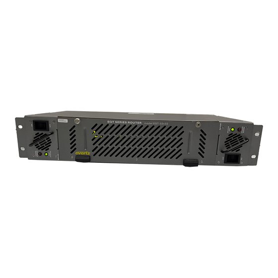
EQT Router User Manual OVERVIEW The EQT is a routing solution for mission critical applications. It has the ability to route up to 32x32 signals in a compact 2RU frame or 16x16, 16x4, 16x2, 32x4 and 32x24 signals in a compact 1RU frame. -
Page 16: Configuration
EQT Router User Manual 1.1. CONFIGURATION The EQT-3232 is housed in a 2RU frame and switches 32 sources to 32 destinations. The EQT-1616, EQT-1604, and EQT-1602-3G-CS are housed in a 1RU frame and switches 16 sources and either 16, 4 or 8 (2 clean/quiet, and 6 auxiliary) destinations respectively. The EQT-3204 and EQT-3224 are housed in 1RU frames and switches 32 inputs and 24 outputs. -
Page 17: Features (-Cs Version Only)
This manual will assist you in the use of the EQT router, and contains all the necessary information to successfully operate this product. If further product information or assistance is required, please contact Evertz or your local Evertz/Quartz distributor. This manual is organized into 7 sections: Overview, Installation, Technical Description, System Control Overview, VistaLINK Remote Monitoring/Control, Configuration and Upgrading Firmware. -
Page 18: Definitions
EQT Router User Manual 1.8. DEFINITIONS 4:2:2: The sampling ratio used in the HDTV digital video signal. For every 4 samples of luminance there are 2 samples each of R-Y (Red minus Luminance) and B-Y (Blue minus Luminance). 16x9: A wide screen television format such as HDTV in which the aspect ratio of the screen is 16 units wide by 9 high as opposed to the 4x3 of normal TV. - Page 19 EQT Router User Manual DROP FRAME: In NTSC systems, where the frame rate is 29.97002618 frames per second, the drop frame mode permits time of day indexing of the frame numbers by dropping certain frame numbers. Specifically frames 0, and 1 at the beginning of each minute except minutes 0,10,20,30,40, &...
- Page 20 EQT Router User Manual SMPTE 272M: The SMPTE standard for embedding audio in serial digital standard definition (SMPTE 259M-C) video signals. SMPTE 274M: The SMPTE standard for bit parallel digital interface for high definition component video signals with an active picture of 1080 lines x 1920 pixels. SMPTE 276M: The SMPTE standard for transmission of AES/EBU Digital Audio Signals Over Coaxial Cable.
-
Page 21: Installation
EQT Router User Manual INSTALLATION 2.1. UNPACKING Remove the equipment carefully from the boxes and check against the Packing List supplied with each unit. This shows what items have been shipped against your order and includes all options. Any error should be reported to your supplier immediately. After you have unpacked the equipment please save all the packing material as this could be useful in the future should the unit need to be returned for maintenance. -
Page 22: Video Inputs And Outputs
EQT Router User Manual CAUTION THIS EQUIPMENT HAS MORE THEN ONE POWER SUPPLY. TO REDUCE THE RISK OF ELECTRIC SHOCK DISCONNECT BOTH POWER SUPPLY CORDS BEFORE SERVICING. ALARM LOCK ETHERNET PWR 2 PWR1 INPUTS OUTPUTS GEN ERROR SERIAL Q-LINK LN/ACT 10/100 PROC OK Q-LINK... -
Page 23: Optical Fiber Handling And Care
EQT Router User Manual Figure 2-5: EQT Rear View with Fiber Inputs and Outputs Note: SFP dual-receivers (inputs) are installed on the left half of the above rear panel, labelled ‘Inputs’. SFP dual-transmitters (outputs) are installed on the right half of the rear panel, labelled ‘Outputs’. A fully populated 32x32 fiber routing matrix will possess 16 dual-transmitters and 16 dual-receivers. -
Page 24: Installing An Sfp Module
2.3.4. Q-LINK Connections (Coax versions ONLY) There is one Q-LINK 75Ω termination BNC connectors located on the rear of the EQT, with a second connector which is a loop through. The EQT supports Evertz control panels that have a Q-Link connection. -
Page 25: Manual Remote Control - Using Q-Link
The rear of the EQT has one BNC connector to allow connection to one terminated external Q-Link. Q- Link is a dedicated control system specific to Evertz brand of Quartz products. The Q-Link system works as a single transmission line with devices connected along the length of the cable. It must be terminated at either end in 75Ω. -
Page 26: Micro-D Serial Connection (-Cs And Eqt-3224 New Rear Plate Only)
EQT Router User Manual As an option it is possible to convert the serial port to RS232 with the following pin-out, as shown in Table 2. RS232 9 WAY FEMALE D-TYPE SIGNAL Table 2: RS232 Pin Out 2.5. MICRO-D SERIAL CONNECTION (-CS AND EQT-3224 NEW REAR PLATE ONLY) The newer rear panels of EQT-3204-CS, EQT-1602-CS and EQT-3224 have one Micro-D male serial connector. -
Page 27: Ethernet Connections
EQT Router User Manual Micro-D to DB9 Split Cable DB9-1 F Provides access to EQT DB9-2 F Provides access to ACO2 slot 1 (1602 and 3204) MIRO-D F DB9-3 F Provides access to ACO2 slot 2 (3204) DB9-4 F Provides access to front panel Table 4: Micro-D to DB9 Split Cable Number Figure 2-6: Micro-D to DB9 Split Cable ... -
Page 28: Table 5: Standard Rj-45 Wiring Colour Codes
EQT Router User Manual The straight-through RJ-45 cable can be purchased or can be constructed using the pin-out information in Table 5. A colour coded wiring table is provided in Table 5 for the current RJ-45 standards (AT&T 258A or EIA/TIA 258B colour coding shown). Also refer to the notes following the table for additional wiring guide information. -
Page 29: Alarm Connector
EQT Router User Manual 2.7. ALARM CONNECTOR A 2-pin alarm terminal provides external alarm indication. This is a simple interface over which television equipment can report the occurrence of internal failures and faults in incoming signals. It is intended for use in all television equipment. The interface consists of an isolated closure, which can assume one of two states: open, or closed. -
Page 30: Reference
CAUTION - TO REDUCE THE RISK OF ELECTRIC SHOCK, EARTHING OF THE EARTH PIN OF THE MAINS PLUGS MUST BE MAINTAINED For NEBS compliant installations, the AC power cords of the EQT Series Router shall be connected to an external surge protection device (SPD). -
Page 31: Removing The Power Supply
2 amps, 250 Volt time delay 5 x 20 mm EQT-3232 Series 3.15 amps, 250 Volt time delay 5 x 20 mm If there is a fuse failure, contact Evertz customer service regarding the power supply immediately. The power supplies are short circuit protected and should not blow the fuse under a short circuit condition. -
Page 32: Figure 2-8: Psu Mounting Screw Locations
EQT, the PSU Mount may not be labeled. For these versions, refer to Figure 2-8 for the location of these screws. The power supply on the clean switch versions are internal and should only be removed by factory trained Evertz service personnel. EQT-3232... -
Page 33: Grounding And Bonding - Nebs Applications
EQT Router User Manual 2.10. GROUNDING AND BONDING – NEBS APPLICATIONS The NEBS compliant version of this equipment is to be connected to a Common Bonding Network. The primary grounding mechanism of the EQT router is through the Earth connector of the AC Mains. For NEBS compliant installations, the AC power cords of the EQT Router shall be secured using retaining clips provided to ensure that proper grounding of the Earth pin of the AC mains plug is maintained. - Page 34 EQT Router User Manual This page left intentionally blank Page 20 Revision 1.9.1...
-
Page 35: Technical Description
EQT Router User Manual TECHNICAL DESCRIPTION 3.1. SPECIFICATIONS 3.1.1. Configuration Inputs: Fixed at 32 or 16 Outputs: Fixed at 32 or 24 or 16 or 8 or 4 (-CS versions, 2 or 4 clean/quiet, 6 or 20 auxiliary) Redundant Protection: Redundant Power Supply (Optional) 3.1.2. -
Page 36: Fiber Outputs (-F Fiber Version)
EQT Router User Manual 3.1.5. Fiber Outputs (-F Fiber version) Number of Fiber Outputs: 2 Reclocked Data Rate: 270Mb/s, 1.485Gb/s, 2.970Gb/s Min. Avg Optical Power -5dBm Output Wavelength 1310nm Max Distance @ 3Gb/s 10km Connectors: LC/PC Fiber Type: Single Mode 3.1.6. -
Page 37: Operation
EQT Router User Manual OPERATION 4.1. SYSTEM OVERVIEW The EQT router is a matrix router that provides a simple cost-effective solution for small router applications. The EQT consists of 32 or 16 equalized inputs and 32, 24, 16, 8 or 4 reclocked outputs. Each input and each output is interfaced through a common crosspoint that is controlled by the main processing unit. -
Page 38: Figure 4-2: Eqt Fiber Block Diagram
EQT Router User Manual Reclocker Optical to Electrical to Fiber (270Mb/s, Fiber Electrical Optical Input 1&2 1.485Gb/s, Output 1&2 Converter Converter 2.970Gb/s) Fiber Optical to Input Electrical Crosspoint 31&32 Converter Reclocker Electrical to Fiber (270Mb/s, Optical Output 1.485Gb/s, Converter 31&32 2.970Gb/s) Ethernet Control Processor... -
Page 39: Figure 4-4: Eqt-3204-3G-Cs Block Diagram
EQT Router User Manual Figure 4-4: EQT-3204-3G-CS Block Diagram Note: The relay protected outputs are Video Outputs 1, 2 in EQT-1602-CS and 1, 2, 13 and 14 in EQT-3204-CS and EQT-3224. Page 25 Revision 1.9.1... -
Page 40: Front View
EQT Router User Manual 4.1.1. Front View The front view of the EQT, as shown in Figure 4-5, Figure 4-6 and Figure 4-7, illustrates the flexibility and ingenuity that was incorporated into the design. Figure 4-5: Front View of EQT-3232 Figure 4-6: Front View of EQT-1616 and EQT-1604 Figure 4-7: Front View of EQT Clean Switch Versions (with Control Panel) The front of the EQT router is accessible at all times by loosening the two thumb screws as shown in... -
Page 41: Figure 4-9: Rear Communication Connections On The Eqt-3232
EQT Router User Manual Figure 4-9: Rear Communication Connections on the EQT-3232 Figure 4-10: Rear Communication Connections on the EQT-1616 and EQT-1604 Figure 4-11: Rear Communication Connections on the newer versions of EQT Fiber Input/Output Version Figure 4-12: Rear Communication Connections on EQT-1602-CS Newer Rear Plates Figure 4-13: Rear Communication Connections on EQT-3204-CS and EQT 3224 Newer Rear Plates Page 27... -
Page 42: System Configuration
EQT Router User Manual 4.2. SYSTEM CONFIGURATION 4.2.1. Communication Settings from the Front Panel (Except EQT-3224 and –CS versions) A shaft encoder and four digit dot-matrix display allow card edge navigation for a set of menus used to configure the EQT router. To enter the menu system, rotate the shaft encoder in either direction. On all menus, there are three selectable items: View, Set and End. - Page 43 2. Set the hyperterminal parameters to 115200,8, none, 1, none. 3. Once prompted with the boot menu, you will be asked for a Login and Password. Use root for username and evertz for password. 4. At the prompt type “ telnet localhost 4000”...
- Page 44 EQT Router User Manual 6. Follow the on-screen instructions to set the IP address 7. Once finished save all the changes. 2. For the ACO2 Slot1 (EQT-1602 and EQT-3204 –CS version only): 1. Connect the serial cable to “DB9-2 F” connector of the breakout cable. 2.
-
Page 45: Accessing The Configuration And Monitoring Menu
IP address, and then followed by 4000. (For example, telnet 192.168.0.0 4000). Or connect the PC to DB9-1 F, use root and evertz for user name and password and then type “telnet localhost 4000” to access the configuration and monitoring menus. -
Page 46: Configuring Network Settings
EQT Router User Manual 4.2.5. Configuring Network Settings The Network Configuration menus are used to configure parameters associated with the Ethernet communications of the device. The following chart provides a brief description of the items available in the Network Configuration menu. Set IP Address Sets the IP Address for the device. -
Page 47: Setting The Engineering/Debug
EQT Router User Manual Displays the input that is currently mapped to each of the outputs View Live XPT Status through the crosspoint. View Video Signal Displays various information regarding both inputs and outputs, such Information as locked status, video standard, and reclocker status. 4.2.8. -
Page 48: Viewing / Setting The Clean Switch Configuration (-Cs Version Only)
EQT Router User Manual Sets the level number for the device (Currently Only Level 1 is Set Level Number supported). Set Xpt Restore at Bootup Sets the XPT to be restore at the bootup. 4.2.10. Viewing / Setting the Clean Switch Configuration (-CS Version Only) The View / Set Video Signal Configuration menus are used to view and set parameters associated with the video signals. -
Page 49: Signal And System Monitoring
Sections 4.4.1 to 4.4.3 provide more details regarding these options. 4.4.1. Controlling the EQT Using Ethernet The EQT supports Evertz control panels that have an Ethernet connection. The EQT supports Quartz (-1) protocol commands over the Ethernet port (slave end) therefore, any control device that supports Quartz protocol can control the EQT via Ethernet. -
Page 50: Controlling The Eqt Using Q-Link
Consult the instruction manual for the respective panels to setup their IP address and configuration. 4.4.2. Controlling the EQT Using Q-Link The EQT router supports Evertz control panels that have a Q-Link connection. Section 6.1.2 describes the method used to setup the EQT for use with Q-Link control panels. Consult the instruction manual for the respective panels to setup their Q-Link address and configuration. -
Page 51: Vistalink® Remote Monitoring/Control
3. A virtual database, known as the Management Information Base (MIB) lists all the variables being monitored, which both the Manager and Agent understand. Please contact Evertz for further information about obtaining a copy of the MIB for interfacing to a third party Manager/NMS. -
Page 52: General Monitoring And Control Parameters
EQT Router User Manual 5.2. GENERAL MONITORING AND CONTROL PARAMETERS The following shows the General tab for the EQT. Table 6 provides further details about each control. Figure 5-1: General Tab (For the 3204) Parameter Description Video Input Standard Sets the video input standard for the device. Card Type Indicates the model of the device. -
Page 53: Input Monitoring Parameters
EQT Router User Manual 5.3. INPUT MONITORING PARAMETERS The following shows the Input Monitor tab for the EQT. Table 7 provides further details about each control. Figure 5-2: Input Monitor Tab Parameter Description Input Status Indicates if a video signal is present (Valid) or not present (Invalid). Table 7: Input Monitor Parameters Page 39 Revision 1.9.1... -
Page 54: Output Control Parameters
EQT Router User Manual 5.4. OUTPUT CONTROL PARAMETERS The following shows the Output Control tab for the EQT. Table 8 provides further details about each control. Figure 5-3: Output Control Tab Parameter Description Output Status Enables or disables video output on the output BNCs. Table 8: Output Control Parameters Page 40 Revision 1.9.1... -
Page 55: Clean Switch Output Control Parameters (-Cs Versions Only)
EQT Router User Manual 5.5. CLEAN SWITCH OUTPUT CONTROL PARAMETERS (–CS VERSIONS ONLY) The following shows the Clean Switch Output Control tab for the EQT. Table 9 provides further details about each control. Figure 5-4: Clean Switch Output Control Tab ... -
Page 56: Reclocker Control Parameters
EQT Router User Manual 5.6. RECLOCKER CONTROL PARAMETERS The following shows the Reclocker Control tab for the EQT. Table 10 provides further details about each control. Figure 5-5: Reclocker Control Tab Parameter Description Reclocker Status Enables or disables the reclocker on the output BNCs. Table 10: Reclocker Control Parameters Page 42 Revision 1.9.1... -
Page 57: Crosspoint Control Parameters
EQT Router User Manual 5.7. CROSSPOINT CONTROL PARAMETERS The following shows the Crosspoint Control tab for the EQT. Table 11 provides further details about each control. Figure 5-6: Crosspoint Control Tab Parameter Description Crosspoint Control Sets the input routed to the output BNCs. Table 11: Crosspoint Control Parameters Page 43 Revision 1.9.1... -
Page 58: General Fault Parameters
EQT Router User Manual 5.8. GENERAL FAULT PARAMETERS The following shows the General Faults tab for the EQT. Table 12 provides further details about each control. Figure 5-7: General Faults Tab Parameter Description Temperature Warning Raises a trap when the temperature exceeds ideal conditions. Raises a trap when the right (when viewed from the front) power Right Power Supply Failure supply fails. -
Page 59: Clean Switch Output Module Control Parameters (-Cs Versions Only)
EQT Router User Manual 5.9. CLEAN SWITCH OUTPUT MODULE CONTROL PARAMETERS (–CS VERSIONS ONLY) The following shows the Module Control tab for the EQT clean switch routers. Table 13 provides further details about each control. Figure 5-8: Module Control Tab Parameter Description Vertical Phase... -
Page 60: Clean Switch Output Audio Control Parameters (-Cs Versions Only)
EQT Router User Manual 5.10. CLEAN SWITCH OUTPUT AUDIO CONTROL PARAMETERS (–CS VERSIONS ONLY) The following shows the Audio Control tab for the EQT clean switch routers. Table 14 provides further details about each control. Figure 5-9: Audio Control Tab Parameter Description Audio Embedded Control... -
Page 61: Clean Switch Output Audio Mixer Parameters (-Cs Versions Only)
EQT Router User Manual 5.11. CLEAN SWITCH OUTPUT AUDIO MIXER PARAMETERS (–CS VERSIONS ONLY) The following shows the Audio Mixer tab for the EQT clean switch routers. Table 15 provides further details about each control. Only the controls for channels 1 to 4 are shown and only the controls for Channel 1 are explained in detail, but the controls for channels 5 to 16 follow the same logic. -
Page 62: Clean Switch Output Fault Parameters (-Cs Versions Only)
EQT Router User Manual 5.12. CLEAN SWITCH OUTPUT FAULT PARAMETERS (-CS VERSIONS ONLY) The following shows the Clean Switch Output Faults tab for the EQT. Table 16 provides further details about each control. Figure 5-11: Clean Switch Output Faults Tab Parameter Description Video Loss... -
Page 63: Configuring The System Using Winsetup
EQT Router User Manual CONFIGURING THE SYSTEM USING WINSETUP The WinSetup program is used to configure most of the routing functions, including control panel operation. It allows such things as the number of signal levels to be defined, which control panels are connected to the system and the names of the inputs and outputs. -
Page 64: Figure 6-2: Winsetup Frame Editor
EQT Router User Manual When generating a new system configuration some of the menus and functions are grayed out (not available). This is deliberate to ‘lead the user through’ the functions that need to be set up. Carry out the following functions to configure the system. -
Page 65: Figure 6-3: Winsetup Source Definition
(4) Destinations: Enter the destination dialog and set up the destination names in the same way as used for the source names. (5) Panels: Enter the panel’s dialog and use the new button. This will show all Evertz panels listed by part number. Select the part number that matches the part number on the panel’s serial number label. -
Page 66: Figure 6-4: Winsetup Panel Configuration
EQT Router User Manual Figure 6-4: WinSetup Panel Configuration Each button can be programmed by selecting the button and then editing the functions in the Key section of the dialog box. Each panel should also be given a name for later identification; E Panel .54 is used in this example. -
Page 67: Communication Port Setup
EQT Router User Manual Note: Configuration downloads to the EQT must be done using port 2500. 6.1. COMMUNICATION PORT SETUP The EQT has several communication ports that require additional setup. This section is used to define all of the interfaces that will be connected to the EQT. Enter the Edit Frame dialog and select the Port Setup tab. -
Page 68: Control Panel Q-Link Interface
EQT Router User Manual Figure 6-6: Ethernet Panels Port Settings 6.1.2. Control Panel Q-Link Interface The control panel Q-Link port is an interface that is defined to allow all properly equipped control panels to connect to the EQT via Q-Link. The Q-Link port can be defined as a port to host panels using Q-Link. The interface is defined as a QLINK1 interface using the Qlink (Hosted Panels) protocol. -
Page 69: Serial Interface
EQT Router User Manual 6.1.3. Serial Interface The serial port is an interface that is defined to provide external automation control of the EQT. The interface is defined as a COM1 interface using the Quartz protocol. The format of the serial protocol is also defined in this dialog using the options that are provided for Baud Rate, Parity, Data bits, Stop bits and Standard (RS232 or RS422). - Page 70 EQT Router User Manual This page left intentionally blank Page 56 Revision 1.9.1...
-
Page 71: Upgrading Firmware
EQT Router User Manual UPGRADING FIRMWARE Upgrading the EQT is done using a standard web browser on any computer that is connected to the same network. The following sections detail methods for upgrading the firmware on the standard EQT, the Clean Switch versions of the EQT, as well as EQT with firmware versions before 1.0 build 001. ... -
Page 72: Figure 7-2: Eqt Upgrade Screen For Upload
EQT Router User Manual Figure 7-2: EQT Upgrade Screen for Upload 3. Once the file is uploaded, it will be verified by the system to ensure it is valid. If the file is valid, an Upgrade button will appear below, as show in Figure 7-3. Figure 7-3: EQT Upgrade Screen for Upgrade Page 58 Revision 1.9.1... -
Page 73: Upgrading -Cs Versions Of The Eqt
EQT Router User Manual 4. After pressing the Upgrade button, the EQT will be upgraded. Once complete, a message indicating that the upgrade was successful will appear at the bottom of the screen as shown in Figure 7-4. Once this message appears, restart the EQT as instructed. Figure 7-4: EQT Upgrade Screen for Success 7.2. -
Page 74: Upgrading From Older Versions Of Firmware
4. Copy the latest IMG file to any directory on your computer. (C:\temp) 5. FTP into the EQT using the following command. Replace 192.168.8.9 with the unique IP of your device as shown in Figure 7-6. Login as user root and Password evertz. Figure 7-6: Run Window for FTP Access Page 60 Revision 1.9.1... -
Page 75: Figure 7-7: Run Window For Telnet Access
EQT Router User Manual 6. Enter the commands below in the FTP window. If all goes well you will see the file transfer via Ethernet to the EQT and a Transfer Complete message will display. type binary cd /tmp put C:\temp\LATEST_IMAGE.img (replace LATEST_IMAGE with the name of the file) close quit... - Page 76 EQT Router User Manual This page left intentionally blank Page 62 Revision 1.9.1...
Need help?
Do you have a question about the EQT Series and is the answer not in the manual?
Questions and answers