Sign In
Upload
Manuals
Brands
evertz Manuals
Network Router
EQT Series
evertz EQT Series Manuals
Manuals and User Guides for evertz EQT Series. We have
2
evertz EQT Series manuals available for free PDF download: System Manual
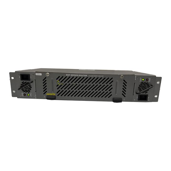
evertz EQT Series System Manual (76 pages)
Brand:
evertz
| Category:
Network Router
| Size: 3 MB
Table of Contents
Table of Contents
9
1 Overview
15
Figure 1-1: the EQT Signal Processing Router
15
Configuration
16
Control
16
Power Supply
16
Technical
16
Features (All Versions)
16
Features (-Cs Version Only)
17
How to Use this Manual
17
Definitions
18
2 Installation
21
Unpacking
21
Physical Installation
21
Router Frames
21
Remote Panels
21
Electrical Connections
21
Figure 2-1: EQT Rear View (EQT-3232)
21
Fiber Input and Output Connections (EQT-3232-3G-F ONLY)
22
Figure 2-2: EQT Rear View (EQT-1616 and EQT-1604)
22
Figure 2-3: EQT Rear View (EQT-1602-CS (Newer Rear Plate))
22
Figure 2-4: EQT Rear View (EQT-3204-CS and EQT-3224 (Newer Rear Plate))
22
Figure 2-5: EQT Rear View with Fiber Inputs and Outputs
23
Optical Fiber Handling and Care
23
Installing an SFP Module
24
Removing an SFP Module
24
Video Inputs and Outputs
22
Video Reference
22
Q-LINK Connections (Coax Versions ONLY)
24
Manual Remote Control - Using Q-Link
25
Serial Connections
25
Table 1: RS422 Pin out
25
Micro-D Serial Connection (-Cs and Eqt-3224 New Rear Plate Only)
26
Table 2: RS232 Pin out
26
Table 3: RS232 Micro-D Port Pin out
26
Ethernet Connections
27
Connecting to an Ethernet Network
27
Figure 2-6: Micro-D to DB9 Split Cable
27
Table 4: Micro-D to DB9 Split Cable Number
27
Table 5: Standard RJ-45 Wiring Colour Codes
28
Alarm Connector
29
Figure 2-7: Example Alarm Circuit
29
Reference
30
Video Reference
30
Selecting Whether the Video Reference Is Terminated
30
Power Supply
30
Removing the Power Supply
31
Figure 2-8: PSU Mounting Screw Locations
32
Grounding and Bonding - Nebs Applications
33
3 Technical Description
35
Specifications
35
Configuration
35
Video Inputs
35
Video Outputs
35
Fiber Inputs (-F Fiber Version)
35
Fiber Outputs (-F Fiber Version)
36
Reference Timing
36
Control
36
Physical
36
Electrical
36
4 Operation
37
System Overview
37
Figure 4-1: EQT Block Diagram
37
Figure 4-2: EQT Fiber Block Diagram
38
Figure 4-3: EQT Clean Switch Block Diagram
38
Figure 4-4: EQT-3204-3G-CS Block Diagram
39
Figure 4-5: Front View of EQT-3232
40
Figure 4-6: Front View of EQT-1616 and EQT-1604
40
Figure 4-7: Front View of EQT Clean Switch Versions (with Control Panel)
40
Figure 4-8: Front View of EQT with Door Open
40
Front View
40
Rear View
40
Figure 4-10: Rear Communication Connections on the EQT-1616 and EQT-1604
41
Figure 4-11: Rear Communication Connections on the Newer Versions of EQT Fiber Input/Output Version
41
Figure 4-12: Rear Communication Connections on EQT-1602-CS Newer Rear Plates
41
Figure 4-13: Rear Communication Connections on EQT-3204-CS and EQT 3224 Newer Rear Plates
41
Figure 4-9: Rear Communication Connections on the EQT-3232
41
System Configuration
42
Communication Settings from the Front Panel (Except EQT-3224 and -CS Versions)
42
Setting the IP Addressing for the EQT Clean Switch
42
Accessing the Configuration and Monitoring Menu
45
Configuration and Monitoring Menu
45
Configuring Network Settings
46
Setting the SNMP Setup
46
Setting the Status Monitoring
46
Setting the Engineering/Debug
47
Viewing / Setting the Frame Configuration
47
Viewing / Setting the Clean Switch Configuration (-CS Version Only)
48
Viewing / Setting the Video Signal Configuration
48
Signal and System Monitoring
49
Control System
49
Controlling the EQT Using Ethernet
49
Controlling the EQT Using Q-Link
50
Controlling the EQT Using Serial
50
5 Vistalink® Remote Monitoring/Control
51
What Is Vistalink
51
General Monitoring and Control Parameters
52
Figure 5-1: General Tab (for the 3204)
52
Table 6: General Parameters
52
Input Monitoring Parameters
53
Figure 5-2: Input Monitor Tab
53
Table 7: Input Monitor Parameters
53
Output Control Parameters
54
Figure 5-3: Output Control Tab
54
Table 8: Output Control Parameters
54
Clean Switch Output Control Parameters (-Cs Versions Only)
55
Figure 5-4: Clean Switch Output Control Tab
55
Table 9: Clean Switch Output Control Parameters
55
Reclocker Control Parameters
56
Figure 5-5: Reclocker Control Tab
56
Table 10: Reclocker Control Parameters
56
Crosspoint Control Parameters
57
Figure 5-6: Crosspoint Control Tab
57
Table 11: Crosspoint Control Parameters
57
General Fault Parameters
58
Figure 5-7: General Faults Tab
58
Table 12: General Fault Parameters
58
Clean Switch Output Module Control Parameters (-Cs Versions Only)
59
Figure 5-8: Module Control Tab
59
Table 13: Module Control Parameters
59
Clean Switch Output Audio Control Parameters (-Cs Versions Only)
60
Figure 5-9: Audio Control Tab
60
Table 14: Audio Control Parameters
60
Clean Switch Output Audio Mixer Parameters (-Cs Versions Only)
61
Figure 5-10: Audio Mixer Tab
61
Table 15: Audio Mixer Parameters
61
Clean Switch Output Fault Parameters (-Cs Versions Only)
62
Figure 5-11: Clean Switch Output Faults Tab
62
Table 16: Clean Switch Output Fault Parameters
62
6 Configuring the System Using Winsetup
63
Figure 6-1: Winsetup Configuration Editor
63
Figure 6-2: Winsetup Frame Editor
64
Figure 6-3: Winsetup Source Definition
65
Figure 6-4: Winsetup Panel Configuration
66
Communication Port Setup
67
Control Panel Ethernet Interface
67
Figure 6-5: Port Setup
67
Control Panel Q-Link Interface
68
Figure 6-6: Ethernet Panels Port Settings
68
Figure 6-7: Q-Link Hosted Panels Port Settings
68
Serial Interface
69
Ethernet Interface
69
Figure 6-8: Serial Port Settings
69
Figure 6-9: Ethernet Port Settings
69
7 Upgrading Firmware
71
Upgrading a Standard Eqt
71
Figure 7-1: EQT Upgrade Screen for Browse
71
Figure 7-2: EQT Upgrade Screen for Upload
72
Figure 7-3: EQT Upgrade Screen for Upgrade
72
Upgrading -Cs Versions of the Eqt
73
Figure 7-4: EQT Upgrade Screen for Success
73
Upgrading from Older Versions of Firmware
74
Figure 7-5: Run Window for FTP Access
74
Figure 7-6: Run Window for FTP Access
74
Figure 7-7: Run Window for Telnet Access
75
Advertisement
evertz EQT Series System Manual (44 pages)
Brand:
evertz
| Category:
Network Hardware
| Size: 1 MB
Table of Contents
Table of Contents
7
Overview
11
Figure 1-1: the EQT Signal Processing Router
11
How to Use this Manual
13
Definitions
14
Installation
17
Unpacking
17
Physical Installation
17
Router Frames
17
Remote Panels
17
Electrical Connections
17
Figure 2-1: EQT Rear View
17
Video Inputs and Outputs
18
Video Reference
18
Fiber Input and Output Connections (EQT-3232-3G-F ONLY)
18
Figure 2-2: EQT Rear View with Fiber Inputs and Outputs
18
Optical Fiber Handling and Care
19
Installing an SFP Module
19
Removing an SFP Module
20
Q-LINK Connections (Coax Version ONLY)
20
Manual Remote Control - Using Q-Link
20
Serial Connections
21
Table 2-1: RS-422 Pin out
21
Ethernet Connections
22
Connecting to an Ethernet Network
22
Table 2-2: RS-232 Pin out
22
Table 2-3: Standard RJ-45 Wiring Color Codes
22
Alarm Connector
23
Reference
24
Video Reference
24
Selecting Whether the Video Reference Is Terminated
24
Figure 2-3: Example Alarm Circuit
24
Power Supply
25
Figure 2-4 - EQT-PS Power Supply
25
Removing the Power Supply
26
Figure 2-5: PSU Mounting Screw Locations
26
Technical Description
27
Specifications
27
Configuration
27
Video Inputs
27
Video Outputs
27
Fiber Inputs (-F Fiber Version)
27
Fiber Outputs (-F Fiber Version)
28
Reference Timing
28
Control
28
Physical
28
Electrical
28
Operation
29
System Overview
29
Figure 4-1: EQT Block Diagram
29
Front View
30
Figure 4-2: EQT Fiber Input/Output Block Diagram
30
Figure 4-3: Front View of EQT
30
Figure 4-4: Front View of EQT with Door Open
30
Rear View
31
System Configuration
31
Setting Communication Settings from the Front Panel
31
Figure 4-5: Rear Communication Connections on the EQT
31
Figure 4-6: Rear Communication Connections on the EQT Fiber Input/Output Version
31
Accessing the Configuration and Monitoring Menu
32
Configuration and Monitoring Menu
33
Configuring Network Settings
33
Setting the Serial Port Setup
34
Setting the SNMP Setup
34
Setting the Panel Setup
34
Setting the Status Monitoring
34
Setting the Engineering/Debug
35
Viewing / Setting the Frame Configuration
35
Viewing / Setting the Video Signal Configuration
35
Signal and System Monitoring
36
Control System
36
Controlling the EQT Using Ethernet
36
Controlling the EQT Using Q-Link
37
Controlling the EQT Using Serial
37
Figure 4-7: Single Q-Link Connection to Multiple Remote Control Panels
37
Configuration
38
Configuring Panels for Use with the Eqt
38
Using Winsetup to Create Panel Configurations
38
Figure 5-1: Winsetup Main Screen
38
Figure 5-2: Winsetup Panel Configuration Screen
39
Exporting Panel Configurations to Panels
40
Adding Panels to the EQT
40
Figure 5-3: Winsetup System Panels Screen
40
Vistalink® Remote Monitoring/Control
41
What Is Vistalink
41
Vistalink
42
Monitored Parameters
42
Controlled Parameters
42
Vistalink Traps
43
Table 6-3: Vistalink ® Traps Parameters
43
Advertisement
Related Products
evertz EQT-3232-3G
evertz EQT-1616-H
evertz EQT-1616-3G
evertz EQT-1602-3G-CS
evertz EQT-3204-3G-CS
evertz EQT-1616-3G-C
evertz EQT-1616-3G-F
evertz EQT-3224-3G
evertz EQT-1604-3G
evertz EQT-1604-H
evertz Categories
Media Converter
Network Hardware
Transmitter
Amplifier
Receiver
More evertz Manuals
Login
Sign In
OR
Sign in with Facebook
Sign in with Google
Upload manual
Upload from disk
Upload from URL