Table of Contents
Advertisement
Quick Links
Declaration of Conformity
According to 47 CFR, Parts 2 and 15 of the FCC Rules
is a Class B digital device that complies with 47 CFR Parts 2 and 15 of the FCC
Rules. Operation is subject to the following two conditions:
1. This device may not cause harmful interference.
2. This device must accept any interference received, including interference
that may cause undesired operation.
This declaration is given to the manufacturer:
509 Valley Way, Milpitas, CA 95035, U.S.A.
The following designated product:
EQUIPMENT : MAINBOARD
MODEL NO. : 6OIV2
CHAINTECH COMPUTER U.S., INC.
Tel: 1-408-935-6988
Fax: 1-408-935-6989
Chaintech President: Simon Ho
Signature:
Advertisement
Table of Contents

Subscribe to Our Youtube Channel
Related Manuals for CHAINTECH 6OIV2


Summary of Contents for CHAINTECH 6OIV2
- Page 1 According to 47 CFR, Parts 2 and 15 of the FCC Rules The following designated product: EQUIPMENT : MAINBOARD MODEL NO. : 6OIV2 is a Class B digital device that complies with 47 CFR Parts 2 and 15 of the FCC Rules. Operation is subject to the following two conditions: 1.
- Page 2 Federal Communications Commission Statement This device complies with FCC Rules Part 15. Operation is subject to the following two conditions: This device may not cause harmful interference This device must accept any interference received, including interference that may cause undesired operation. This equipment has been tested and found to comply with the limits for a Class B digital device, pursuant to Part 15 of the FCC Rules.
-
Page 3: Table Of Contents
T T T T T ab le of Contents le of Contents ab le of Contents le of Contents le of Contents Chapter 1 Introduction ................ 1 Product Specifications ............1 Product Feature ..............4 Package Content ..............5 Chapter 2 Hardware Setup ..............7 Introduction to Jumpers ............ -
Page 4: Chapter 1 Introduction
Introduction Chapter 1 Introduction 1-1 Product Specifications r r r r r Processor - Supports Socket-370 processors - Supports 370-pin ZIF socket w/ EMI ground pad for future boxed Pentium-III processors - Supports 66/100/133 MHz system clock speeds r r r r r Chipset - Intel 815E GMCH + ICH2 AGPset with integrated 2D/3D graphics controller r r r r r DRAM Memory - Two 3.3V 168-pin DIMM sockets support up to 512MB... - Page 5 Chapter 1 r r r r r Embedded Super I/O Functions ITE 8712 LPC I/O chip with System Monitor Hardware - One parallel supports SPP/ECP/EPP and two serial (16550A compliant) ports - One floppy disk drive connector supports up to 2.88MB, Japanese 3- Mode and 1Mbps transfer rate - Supports HPSIR, ASKIR and CIR function shared with 2 serial port...
- Page 6 Introduction r r r r r Switching Power Supply Requirement Table 1-1...
-
Page 7: Product Feature
Chapter 1 1-2 Product Features Complete CPU protection with OVT (Over Voltage Protect) and OCP (Over Current Protect) technology - Advanced Management Features: * Power-on events: Mouse movement or clicks, Keyboard password, WOL(Wake-on-LAN), AOL (Alert-on-LAN) network card, Modem ring, RTC Alarm, CIR and USBs * Software power-off control for Win98 * Over-ride power button * Three states advanced Power-failure recovery: Always On, Always Off, Last... -
Page 8: Package Content
Introduction 1-3 Package Contents 1-3 Package Contents 1-3 Package Contents 1-3 Package Contents 1-3 Package Contents This product comes with the following components: r One mainboard r One 40-pin Ultra DMA-66/100 IDE connector ribbon cable (Figure 1-1) * Color coded connection for UDMA-66/100 cable Blue to mainboard, Gray to Master and Black to slave r One 34-pin floppy disk drive ribbon cable (Figure 1-2) r Optional LTI-II Panel link adapter for LCD/TV-out( Figure 1-3) - Page 9 Chapter 1 Memo...
-
Page 10: Chapter 2 Hardware Setup
Hardware Setup Chapter 2 Hardware Setup If your mainboard has already been installed in your computer you may still need to refer to this chapter if you plan to upgrade your system's hardware. Be sure to disconnect the power cable from the power source before performing any work on your mainboard, i. -
Page 11: Installing A Cpu In A Socket 370
Chapter 2 2-2 Installing a CPU in a Socket 370 The Intel Socket 370, designed for the Celeron and Coppermine processors, has been incorporated as a standard mainboard specification.To insert your CPU into Socket 370 please do the following: 2. Pull up the lever of Socket 370 so that it is perpendicular with the surface of the mainboard. - Page 12 Hardware Setup Overclocking Operating a CPU at a higher frequency than it's specification allows is called overclocking. If the CPU frequency is set at a higher frequency than it's specification allows, it may or may not run at that frequency, depending on the quality of your CPU and the extent to which the frequency has been overset.
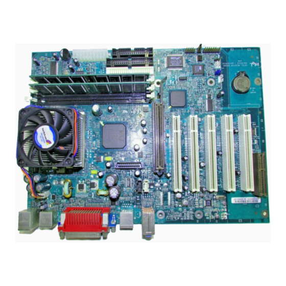
- Page 13 Chapter 2 CN5,CN7,CN8 JP3,JP4, JP1/JP2,JP5, CN6,CN10,LTI1 FAN1 CN9,CN11 JP9/JP10 JP7,JP8,JP11,CN12, CN13,CN14,,FAN2 Printer Port Game Port PS/2 Mouse COM1 PS/2 Keyboard USB 0/1 Line-out Line-in Mic-in...
- Page 14 Hardware Setup JP & CN No. Function Page JP1/JP2 Audio Line out/ Speaker out PS/2 keyboard Power On Funtion USB Power On Function Primary Audio CODEC selector Chassis Intrusion Dectection Infrared / Consumer Infrared JP9/JP10 System Bus Frequency Setting JP11 Clear CMOS Data PS/2 Mouse and Keyboard Ports USB 0/1Ports...
-
Page 15: Connector And Jumper Settings
Chapter 2 2-4 Connector and Jumper Settings Connectors are used to link the system board with other parts of the system, including the power supply, the keyboard, and the various controllers on the front panel of the system case. The power supply connector is the last connection to be made while installing a mainboard. -
Page 16: Feature Explanations Software Power-Off Control
Hardware Setup Front Panel Connector Set (CN14) A through F A. Over-ride Power Button Connector The power button on the ATX chassis can be used as a normal power switch as well as a device to activate Advanced Power Management Suspend mode. -
Page 17: Blinking Led In Suspend Mode
Chapter 2 C. Green Switch/Green LED Connector Some ATX cases provide a Green switch which is used to put the system in Suspend mode. In Suspend mode, the power supply to the system is reduced to a trickle, the CPU clock is stopped, and the CPU core is in it's minimum power state. - Page 18 Hardware Setup Audio Line_out or Speaker_out (JP1/JP2) Line_out Speaker_ out (default) This jumper allows you to select between audio line-out or speaker out function. Set both JP2 and JP3 pins to 1-2 for line-out function or set both JP2 and JP3 pins to 2-3 for speaker out function.. PS/2 Keyboard Power On Function (JP3) USB Device Power On Function (JP4) Disable(default)
- Page 19 Chapter 2 Primary Audio CODEC Selector (JP5) Onboard CODEC (Default) CNR (Soft-Audio/Modem riser) Short pin 1-2 to enable onboard AC`97 CODEC. Short pin 2-3 to enable CNR (Soft Audio/Modem riser). Chassis Intrusion Detection (JP7) This board supports the chassis instruction monitoring feature of the management extension hardware by means of a mechanical or photo sensor switch attached to the motherboard through this...
- Page 20 Hardware Setup CPU Bus Frequency (JP9/JP10) JP10 Auto 100MHZ 133MHz Open This jumper allows the CPU bus frequency to be determined either by the CPU or the user. Set both jumper cups to pin 1-2 (default) if you are not sure what frequency your CPU support.
- Page 21 Chapter 2 USB 0/1Ports and USB 2/3 Connector(CN2/CN12) CN12 This board contains a USB Host controller and includes a root hub with two USB 0/1 ports (meets USB Rev 1.0 spec.) and a connector for optional USB Adaptor (USB2/3). Four USB peripherals or hub devices are able to be connected.
- Page 22 Hardware Setup WOL (Wake-on-LAN) Connector (CN8) Enable the Wake Up On LAN selection in BIOS's Power Management Menu to use this function. The capability to remotely manage PCs on a network is a significant factor in reducing administrative and ownership costs. Magic Packet technology is designed to give WOL (Wake-on- LAN) capability to the LAN controller.
- Page 23 Chapter 2 Alert On LAN Connector (CN13) CPU/CASE Cooling Fan Connectors FAN1/FAN2) These added connectors allow the fan to draw their power from the mainboard instead of the disk drive connector. The board's management extension hardware is able to detect the CPU and system fan speed in rpm (revolutions per minute).
-
Page 24: Main Memory Configuration
Hardware Setup 2-5 Main Memory Configuration The DRAM memory system consists of three banks and the memory size ranges from 16~512 MBytes. It does not matter which bank you want to install first. DRAM Specifications FSB Freq. (MHz) System Memory Bus Freq. (MHz) DIMM type : 3.3V, unbuffered, registered, 64/72-bit SDRAM with SPD* Module size: Single/double-side 16/32/64/128/256 MBytes Parity... - Page 25 Chapter 2 Memo...
-
Page 26: Chapter 3 Award Bios Setup Program
Award BIOS Setup Program Chapter 3 3 3 3 3 3 Award BIOS Setup Program Award's BIOS ROM has a built-in setup program that allows users to modify the basic system configuration. This information is stored in CMOS RAM so that it can retain the setup information, even when the power is turned off. - Page 27 Chapter 3 Memo...
-
Page 28: Chapter 4 Brief Software Driver Guide
Chapter 4 Brief Software Driver Guide The Mainboard Software Guide is found on the CD-ROM that is enclosed with your mainboard and is a PDF file which must be viewed with Adobe's freeware called ® Acrobat Reader. The Acrobat Reader software is also included on the same CD- ROM. - Page 29 Chapter 4 Memo...
-
Page 30: Appendix I On Board I/O Addresses & Irq Maps
Appendix I Appendix I Appendix I Appendix I Appendix I On Board I/O Addresses & IRQ Maps System Resource I/O Address 1. Timer IRQ0 040, 043 2. Keyboard IRQ1 060, 064 3. Programmable INT IRQ2 0020, 0021, 00A0, 00A1 4. COM2(B) IRQ3 2F8, 2FF 5. - Page 31 User's Manual Memo...
-
Page 32: Appendix Ii Embedded Flash Utility
Appendix II Appendix II Appendix II Appendix II Appendix II Embedded Flash Utility This mainboard is equipped with an Erasable Flash ROM and an Embedded Flash Utility which allows the user to update the BIOS to a newer version. Embedded Flash Utility eases BIOS upgrade and eliminate the compatibility issue between different Flash ROM type and version of Flash utility. - Page 33 User's Manual Memo...
Need help?
Do you have a question about the 6OIV2 and is the answer not in the manual?
Questions and answers