Table of Contents
Advertisement
Quick Links
© Copyright 2003 - 2007
EVERTZ MICROSYSTEMS LTD.
5288 John Lucas Drive,
Burlington, Ontario,
Canada,
L7L 5Z9
Phone:
905-335-3700
Sales Fax:
905-335-3573
Service Fax:
905-335-0909
Internet:
Sales:
Tech Support: service@evertz.com
Web Page:
Version 1.1 May 2007
The material contained in this manual consists of information that is the property of Evertz Microsystems and is intended solely for
the use of purchasers of the X Series Routers. Evertz Microsystems expressly prohibits the use of this manual for any purpose
other than the operation of the Routers.
All rights reserved. No part of this publication may be reproduced without the express written permission of Evertz Microsystems
Ltd. Copies of this guide can be ordered from your Evertz products dealer or from Evertz Microsystems.
X- Series Optical Routers
Instruction Manual
sales@evertz.com
http://www.evertz.com
Advertisement
Table of Contents

Related Manuals for evertz X Series


Summary of Contents for evertz X Series
- Page 1 The material contained in this manual consists of information that is the property of Evertz Microsystems and is intended solely for the use of purchasers of the X Series Routers. Evertz Microsystems expressly prohibits the use of this manual for any purpose other than the operation of the Routers.
- Page 2 WARNING Changes or Modifications not expressly approved by Evertz Microsystems Ltd. could void the user’s authority to operate the equipment. Use of unshielded plugs or cables may cause radiation interference. Properly shielded interface cables...
- Page 3 Evertz products are for informational use only and are not warranties of future performance, either express or implied. The only warranty offered by Evertz in relation to this product is the Evertz standard limited warranty, stated in the sales contract or order confirmation form.
- Page 4 X – Series Optical Routers X-Series Optical to Optical and Optical to Electrical Crosspoints This page left intentionally blank Revision 1.1...
-
Page 5: Table Of Contents
X – Series Optical Routers X-Series Optical to Optical and Optical/Electrical Crosspoints TABLE OF CONTENTS OVERVIEW ........................1 INSTALLATION ......................... 5 2.1. REAR PANEL OVERVIEW......................5 2.1.1. Optical Connections ....................... 6 2.1.2. Coaxial Connections ......................6 2.1.3. Ethernet Network Connections ....................6 2.1.4. - Page 6 X – Series Optical Routers X-Series Optical to Optical and Optical to Electrical Crosspoints 4.5.1.1. Inputs............................16 4.5.1.2. Outputs............................17 4.5.1.3. Display Settings ........................17 4.5.1.4. Configuring New Crosspoints in Grid View ................17 4.5.2. Quick Take Tab........................19 4.5.3. Salvo Control........................
- Page 7 X – Series Optical Routers X-Series Optical to Optical and Optical to Electrical Crosspoints WARNING Never look directly into an optical fiber. Non-reversible damage to the eye can occur in a matter of milliseconds. Do not hook up the X-series optical router outputs that output more than -7dBm of power (see specifications for output power of various laser types) and high sensitivity receiver cards (with a –...
- Page 8 X – Series Optical Routers X-Series Optical to Optical and Optical to Electrical Crosspoints This page left intentionally blank Revision 1.1...
-
Page 9: Overview
X – Series Optical Routers X-Series Optical and Optical/Electrical Crosspoints OVERVIEW The X-3232-EO is a VistaLINK capable electrical/optical router for digital electrical or optical signals with ® rates up to 3Gb/s. The X-3232-EO can accept signals on any of its 16 optical or 16 electrical inputs and route them to any number of its 16 optical and 16 electrical outputs. - Page 10 X – Series Optical Routers X-Series Optical and Optical/Electrical Crosspoints X-0808-OO Optical Router Features: • 8 fiber optic inputs and outputs • Provides optical routing, regeneration (amplification, reshaping) and wavelength management • Data rate independent to 3Gb/s • Handles video, audio, datacom and telecom signals •...
-
Page 11: Figure 1-1: X-0808-Oo Block Diagram
X – Series Optical Routers X-Series Optical and Optical/Electrical Crosspoints Optical Optical Inputs Outputs Ethernet Port RS232 Local VistaLINK ® Router Control Indication Interface Figure 1-1: X-0808-OO Block Diagram Optical Optical Inputs Outputs Ethernet Port RS232 Local VistaLINK ® Router Control Indication Interface Figure 1-2: X-1616-OO Block Diagram... -
Page 12: Figure 1-3: X-3232-Eo Block Diagram
X – Series Optical Routers X-Series Optical and Optical/Electrical Crosspoints Fiber Inputs Fiber Outputs Electrical Inputs Driver Driver Driver Driver Driver Driver Driver Driver Driver Driver Driver Driver Driver Electrical Driver Driver Driver Outputs Ethernet Port RS232 Router Control Local VistaLINK ®... -
Page 13: Installation
X – Series Optical Routers X-Series Optical and Optical/Electrical Crosspoints INSTALLATION Figure 2-1 to Figure 2-3 shows the rear panels of the X-series optical routers. Sections 2.1.1 to 2.1.5 describe the specific coaxial, optical, control signals and power connections that should be connected to the optical router units. -
Page 14: Optical Connections
X – Series Optical Routers X-Series Optical and Optical/Electrical Crosspoints 2.1.1. Optical Connections FIBER INPUTS The X-series optical routers are available with female SC/PC (shown), ST/PC or FC/PC type optical input connectors. FIBER OUTPUTS The X-series optical routers are available with a female SC/PC (shown), ST/PC or FC/PC type optical output connectors. -
Page 15: Care And Handling Of Optical Fiber
Never look directly into an optical fiber. Non-reversible damage to the eye can occur in a matter of milliseconds. 2.3.2. Assembly Assembly or repair of the laser sub-module is done only at Evertz facility and performed only by qualified ®... -
Page 16: Handling And Connecting Fibers
The transmission characteristics of the fiber are dependent on the shape of the optical core and therefore care must be taken to prevent fiber damage due to heavy objects or abrupt fiber bending. Evertz ®... -
Page 17: Specifications
X – Series Optical Routers X-Series Optical and Optical/Electrical Crosspoints SPECIFICATIONS 3.1. ELECTRICAL OUTPUT Number of Inputs: 16 on X-3232-EO Standards: Any scrambled, 8b/10b or similarly encoded signal from 155Mb/s to 3.125Gb/s Connector: BNC per IEC 60169-8 Amendment 2 Return Loss: >... -
Page 18: Compliance
X – Series Optical Routers X-Series Optical and Optical/Electrical Crosspoints 3.6. COMPLIANCE Electrical Safety: CSA Listed to CSA C22.2 No. 60065-03, UL 60065-03 IEC 60065-(2001-12) 7th Edition Complies with CE Low voltage directive 93/68/EEC EMI/RFI: Complies with FCC regulations for class A devices. Complies with EU EMC directive 89/336/EEC. -
Page 19: Operation
X – Series Optical Routers X-Series Optical and Optical/Electrical Crosspoints OPERATION 4.1. STATUS INDICATOR LEDs The X-series optical routers have 4 LED Status indicators on the front panel to show operational status of the unit at a glance. Figure 4-1: X-Series Optical Router Status Indicators PSU STATUS 1 GREEN Power Supply 1 functioning properly... -
Page 20: Terminal Program Setup
X – Series Optical Routers X-Series Optical and Optical/Electrical Crosspoints 4.2.1. Terminal Program Setup 1. Start the terminal program and configure the port settings of the terminal program as follows: Baud 115200 Data bits Parity None Stop bits Flow Control None 2. -
Page 21: Snmp Configuration
4.2.5. Audio Configuration The Audio Configuration menu is not used at this time. 4.2.6. Engineering Debug Utility The Engineering Debug Utility is used by Evertz Technicians during debug and analysis of the router. It ® is not recommended for use by customers. -
Page 22: Crosspoint Configuration
X – Series Optical Routers X-Series Optical and Optical/Electrical Crosspoints 4.3. CROSSPOINT CONFIGURATION All crosspoint control is facilitated via VistaLINK or a Network Control Panel (X-NCP2). The router must ® be configured to be on the same subnet as the PC running the VistaLINK client or X-NCP2 in order to ®... -
Page 23: Ip Address
X – Series Optical Routers X-Series Optical and Optical/Electrical Crosspoints Figure 4-3: VistaLINK Screen Top Edge ® 4.4.1. IP Address The top of the screen displays the IP Address of the connected device, for example, 192.168.8.51 in Figure 4-3. To set the IP Address of the Router, refer to section 4.2. 4.4.2. -
Page 24: Global Apply
X – Series Optical Routers X-Series Optical and Optical/Electrical Crosspoints 4.4.7. Global Apply This button will send a single update to all routers of the same type to apply any crosspoint changes in VistaLINK that have been made since the last refresh. ®... -
Page 25: Outputs
X – Series Optical Routers X-Series Optical and Optical/Electrical Crosspoints 4.5.1.2. Outputs Each of the available destinations from the router are shown in the row labeled Outputs. They will each be numbered and have a default name beside them. Outputs 1 to 16 are Optical outputs and 17 to 32 (when available) are Coaxial ports. -
Page 26: Figure 4-7: Step 1 - Select The New Crosspoint By Clicking On It
X – Series Optical Routers X-Series Optical and Optical/Electrical Crosspoints Figure 4-7: Step 1 – Select the new crosspoint by clicking on it Figure 4-8: Step 2 – Press the Apply button X-Series Optical -18 Revision 1.1... -
Page 27: Quick Take Tab
X – Series Optical Routers X-Series Optical and Optical/Electrical Crosspoints Figure 4-9: Grid view updates to show newly implemented changes 4.5.2. Quick Take Tab The Quick Take tab allows you to quickly assign an input to an output from a dropdown menu. This comes in handy when your input and output selection list is large. -
Page 28: Salvo Control
X – Series Optical Routers X-Series Optical and Optical/Electrical Crosspoints Figure 4-10: Quick Take Tab - Selecting an Input (Method 1) Figure 4-11: Quick Take Tab - Selecting an Input (Method 2) 4.5.3. Salvo Control Salvo Control provides the ability to save the configuration of the crosspoints so that the saved configuration can be loaded at a later date. -
Page 29: Storing A New Crosspoint Map
X – Series Optical Routers X-Series Optical and Optical/Electrical Crosspoints Figure 4-12: Retrieving Current Crosspoint Settings 4.5.3.1. Storing a New Crosspoint Map To save a new configuration map select, from the drop down menu (Figure 4-14), an empty Salvo slot or a pre-configured slot that you want to overwrite. -
Page 30: Restoring A Saved Crosspoint Map
X – Series Optical Routers X-Series Optical and Optical/Electrical Crosspoints Figure 4-13: Saving a new crosspoint map into a Salvo slot 4.5.3.2. Restoring a Saved Crosspoint Map Retrieve a previously saved crosspoint map, by selecting the corresponding slot from the drop down menu (Figure 4-14). -
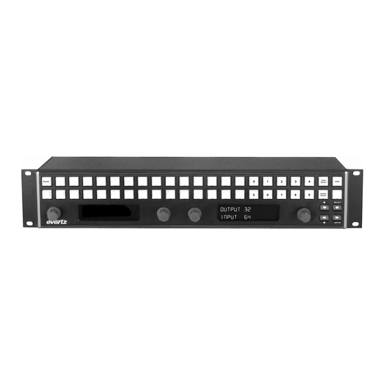
Page 31: Control Tab And Password Settings In Vistalink
Figure 4-15: X-NCP2 Router Control Panel The Evertz X-NCP2 control panel is a multi-function control panel used to control the X-Series router, as well as other Evertz products. The control panel may be connected directly to the router’s Ethernet port (using a crossover Ethernet cable) or to a hub or switch, which is connected to the router’s Ethernet port... -
Page 32: Adding X-Series Router Frame Controller To Xncp2 Control List
X – Series Optical Routers X-Series Optical and Optical/Electrical Crosspoints 4.7.1. Adding X-Series Router Frame Controller to XNCP2 Control List The addition of X-Series router frame controllers can be performed once the XNCP2 panel and X-Series frame controllers are on the same IP subnet. Follow this procedure to add a frame: 1. -
Page 33: Example 2: Rotary Knob Control To Switch Input 2 To Output 5
X – Series Optical Routers X-Series Optical and Optical/Electrical Crosspoints 4. Press [INPUT SELECT] to put the panel into input selection mode. The numeric buttons 0-9 will illuminate. 5. Use the numeric buttons to select the desired input (i.e. 2) by pressing [2], followed by [ENTER] to exit the input selection mode. -
Page 34: Upgrading The Firmware
486 PC or better with a 16550 UART based communications port is recommended. • “Straight-thru” serial extension cable (DB9 female to DB9 male). • Terminal program that is capable of X-modem file transfer protocol (such as HyperTerminal). • New firmware supplied by Evertz ® 5.2. - Page 35 X – Series Optical Routers X-Series Optical and Optical/Electrical Crosspoints Baud 115200 Data bits Parity None Stop bits Flow Control None 5. Apply power to the router. After the unit powers up, a banner with the boot code version information should appear in the terminal window. The cursor should be spinning for about 5 seconds then the unit will continue to boot.
Need help?
Do you have a question about the X Series and is the answer not in the manual?
Questions and answers