Sign In
Upload
Manuals
Brands
evertz Manuals
Network Hardware
VIP-X
evertz VIP-X Multiviewer Equipment Manuals
Manuals and User Guides for evertz VIP-X Multiviewer Equipment. We have
1
evertz VIP-X Multiviewer Equipment manual available for free PDF download: System Manual
evertz VIP-X System Manual (96 pages)
Brand:
evertz
| Category:
Network Hardware
| Size: 2 MB
Table of Contents
Table of Contents
5
Overview
13
Figure 1-1: VIPX64, VIPX128, VIPX288 & Mvp/Maestro Control Software
13
X-Link Enabled Routers
14
Figure 1-2: Flow of Output
14
X-Link Interconnect
15
Figure 1-3: X-LINK Interconnect
15
Table 1-1: X-LINK Enable Router Outputs
15
Hardware Details
17
Router Platforms
17
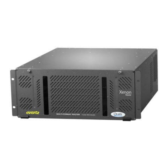
Xenon 4RU
17
Xenon 8RU
17
Figure 2-1: Xenon 4RU - 64X64 Router
17
Figure 2-2: Xenon 8RU - 128X128 Video Router
17
Eqx 16Ru
18
Figure 2-3: EQX 16RU - 288X288 Router
18
Eqx 26Ru
19
Figure 2-4: EQX 26RU - 576X576 Router
19
Vip-X Components
20
Xe-Op32Sx-Xlink
20
Xe-Op32Hx-Xlink
20
Figure 2-5: XE-OP32SX-XLINK
20
Figure 2-6: XE-OP32HX-XLINK
20
Eqx-Op288-Xlink
21
Eqx-Op576-Xlink
21
Figure 2-7: EQX-OP288-XLINK
21
Figure 2-8: EQX-OP576-XLINK
21
Eqx-Op36-Xlink
22
Figure 2-9: EQX-OP36-XLINK
22
X-LINK Cable
23
Figure 2-10: XLINK-BHP-5
23
Xlink-Bhp2U-96C
24
Figure 2-11: Front Panel View of the XLINK-BHP2U-96C
24
Figure 2-12: Rear Panel View of the XLINK-BHP2U-96C
24
3000Mvp-Rp4-Xlink
25
Figure 2-13: 3000MVP-RP4-XLINK Rear Plate
25
7767Vipx-Rp2
26
Figure 2-14: VIPX-RP2 Rear Plate
26
7700Fr-D Frame
27
Figure 2-15: Distribution of X-LINK Connections to the 7767Vipx16X2
27
Figure 2-16: Distribution of X-LINK Connections to the 7767Vipx8X2
27
Figure 2-17: 7700FR-D Frame
27
7700Fr-Dq Frame
28
Hardware Installation
29
Racking Vip-X Frames
29
Xenon 4RU and 8RU
29
EQX 16RU and 26RU
29
7700Fr-D / 7700Fr-Dq
29
Installing Vip-X Rear Panels
29
Installing XE-Op32Xx-XLINK Output Module in Xenon
29
Figure 3-1: Xenon 4RU with One XE-OP32HX-XLINK Output Card Installed
30
Figure 3-2: Xenon 8RU with Two XE-OP32HX-XLINK Output Cards Installed
30
Installing EQX-OP288-XLINK and EQX-OP576-XLINK Rear Module in EQX 16RU
31
Installing EQX-OP36-XLINK Output Card in EQX 26RU
31
Figure 3-3: EQX 16RU with EQX-OP288-XLINK Installed (Two X-LINK Cables Installed)
31
Installing the 7767VIPX-RP2 Rear Plate in the 7700FR-D Frame
32
Figure 3-4: 7700FR-D with Two 7767VIPX-RP2 Installed
32
Installing the XLINK Cable
33
System Communication
35
Network Connectivity
35
Xenon Based VIP-X Solution
35
Figure 4-1: Network Connectivity Diagram - Xenon Router
35
EQX Based VIP-X Solution
36
Figure 4-2: Network Connectivity Diagram - EQX 16RU Router
36
67Vipx8X2, 7767Vipx16X2 Modules
37
Video Inputs and Outputs
37
Figure 5-1: 7767VIPX-RP2 Rear Plate
37
Genlock Reference
38
DVI Video Connections
38
Table 5-1: Supported Resolutions at 50Hz and 60Hz
38
General Purpose Inputs and Outputs
39
Figure 5-2: GPI Input Circuitry
39
Figure 5-3: GPO Output Circuitry
39
Figure 5-4: Interfacing Gpis to a High Voltage GPI System
40
Ltc and Serial Data Inputs (Auxiliary Interface)
41
Figure 5-5: Rear Plate - Ports for Attaching the HD-15
41
Figure 5-6: 7767Vipx16X2/8X2 HD-15 General Purpose Pin-Out
42
Table 5-2: HD-15 Pin-Out
42
Ethernet Network Connections
43
Figure 5-7: Rear Plate - Ethernet Ports
43
Table 5-3: Standard RJ45 Wiring Colour Codes
44
7767Vipx8X2/16X2 Block Diagram
46
Figure 1-2: 7767Vipx8X2/16X2 Block Diagram
46
Technical Description
47
7767Vipx8X2 Specifications
47
Serial Video Inputs
47
Background (Computer) Video Input
47
Display Video Output
47
Serial Video Output
48
Genlock Input
48
General Purpose Interface I/O (GPI/GPO)
48
Input/Output Serial Port
48
Ethernet
48
Electrical
48
Physical
48
7767Vipx16X2 Specifications
49
Serial Video Inputs
49
Background (Computer) Video Input
49
Display Video Output
49
Serial Video Output
49
Genlock Input
50
General Purpose Interface I/O (GPI/GPO)
50
Input/Output Serial Port
50
Ethernet
50
Electrical
50
Physical
50
Status Leds
51
Module Status Leds
51
Video Status Led and Card Edge 4-Character Display
51
User Jumpers
53
Selecting Whether Local Faults on the Board will be Monitored by the Global Frame Status
53
Figure 9-1: Location of Jumpers (7700G4X)
53
Configuring the Module for Firmware Upgrades Via Serial Port
54
Module Configuration
55
Configuring the Module Via the Card Edge Menu
55
Configuring the Display
56
Table 8-1: Top Menu Structure
56
Configuring the Module Using the Module Serial Port
57
Network Configuration
58
On Board Server Setup
59
SNMP Configuration
60
UMD Setup
60
Auxiliary Serial Port Setup
61
SNTP Setup - Network Time Protocol
61
Network Audio Setup - Future Enhancement Feature
62
Nielsen Configuration
62
Web Server Interface
63
Card Setup: Display Setup
63
Card Setup: Network Setup
64
Figure 8-1: Display Setup
64
Card Setup: SNMP Setup
65
Figure 8-2: Network Setup
65
Figure 8-3: SNMP Setup
65
Card Setup: UMD Setup
66
Figure 8-4: UMD Setup
66
Card Setup: Server Setup
67
Figure 8-5: Server Setup
67
Mvp/Vip Maestro Software
68
Upgrading Firmware
69
Upgrading the Firmware Using Ftp
69
Step 1 - Determine the IP Addresses
69
Step 2 - Establishing a Valid Network Connection
69
Step 3 - Upgrading the Application Code
70
Figure 10-1: Run Window
70
Figure 10-2: Pinging the IP Address
70
Step 4 - Completing the Upgrade
72
Figure 10-3: Upgrade Window
72
Upgrading the Firmware Using Rs-232 Serial Cable
73
Step 1 - Setup
73
Step 2 - Invoke Upload Mode from the Terminal Program
73
Step 3 - Uploading the New Firmware
74
Step 4 - Completing the Upgrade
74
Setting up Protocols
75
Setting up Vipx to Work with Image Video Protocol
75
Figure 11-1: Auxiliary Port Setup Menu
75
Setting up Vipx to Work with Tsl Protocol
76
Figure 11-2: under Monitor Display Setup
76
Figure 11-3: Auxiliary Serial Port Settings
77
Figure 11-4: under Monitor Display Setup Settings
77
Setting up Vipx to Work with X-Y Protocol
78
Creating the Text Files
78
Figure 11-5: Source ID and String
78
Setting up the Display Card(S)
79
Figure 11-6: Sample Text Files
79
Figure 11-7: Auxiliary Serial Port Setup
80
Figure 11-8: Setting up XY Integrator Protocol Operation
80
Setting up Vipx to Work with Ascii Protocol
81
Creating the Text File
81
Figure 11-9: Command Displayed on the Output Display
81
Figure 11-10: Input ID and String
81
Setting up the Display Card(S)
82
Figure 11-11: Auxiliary Serial Port Setup Menu
82
Figure 11-12: under Monitor Display Setup Menu
82
System Manager Software
85
Installing Software
85
Configuring a System
85
Figure 12-1: Unlocking the Server
86
Figure 12-2: System Connection Status Window
86
Configuring the 3000 Dcp Desktop Control Panel
87
For Pc - Dcp Setup
87
Vistalink ® Remote Monitoring/Control
89
What Is Vistalink
89
Appendix A: Din Specifications
91
Advertisement
Advertisement
Related Products
evertz VistaLINK 7700 MultiFrame
evertz 2400ODU
evertz 3406FR-HDBNC
evertz 3700FR Series
evertz 3700FR-48VDC
evertz 3700FR-IP-48VDC
evertz 5010-GPSII
evertz 5010-GPSII-VITC
evertz 5600ACO
evertz 5600ACO2
evertz Categories
Media Converter
Network Hardware
Transmitter
Amplifier
Receiver
More evertz Manuals
Login
Sign In
OR
Sign in with Facebook
Sign in with Google
Upload manual
Upload from disk
Upload from URL