
Related Manuals for Bomar Ergonomic 320.250 GH


Summary of Contents for Bomar Ergonomic 320.250 GH
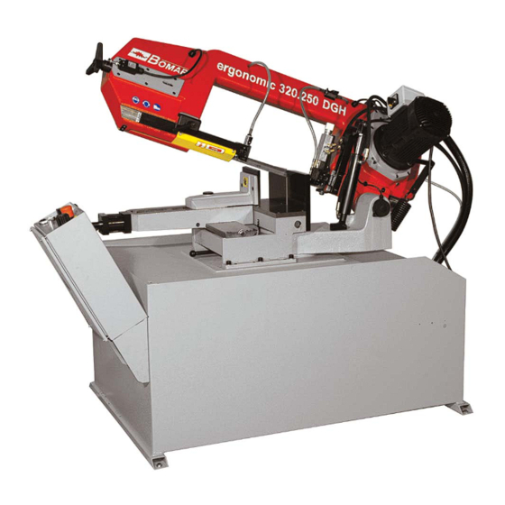
- Page 1 Series Ergonomic Ergonomic 320.250 GH Operating instructions Before transporting and using the machine, please read the instructions thoroughly! Seriové číslo / Serien Nummer / Serial Number ___________________...
- Page 2 Czech Republic, EU www: http://www.bomar.cz We are available: Mondays to Fridays – 16 Version: 1.04 / Mar. 2010 rev. 1 BOMAR, spol. s r.o. © – Subject to modifications and amendments. Manual version: 1.04 / Mar. 2010 Manual rev.:...
- Page 4 Manual version: 1.04 / Mar. 2010 Manual rev.:...
-
Page 5: Table Of Contents
Content 1. SAFETY NOTES ................ 7 1.1. Machine determination ................................8 1.2. Protective suit and personal safety ..........................8 1.3. Safety notes for machine operator ..........................9 1.4. Safety notes for the servicing and repairs ........................9 ... - Page 6 ASSEMBLIES FOR SPARE PARTS ORDER ........79 7.1. Ergonomic 320.250 GH ................................ 80 7.2. Kusovník / Stückliste / Piece list – Ergonomic 320.250 GH ................. 81 7.3. Rameno / Sägerahmen / Saw arm ..........................82 7.4.
-
Page 7: Safety Notes
Safety notes... -
Page 8: Machine Determination
1.1. Machine determination The band saws Ergonomic 320.250 GH and Ergonomic 320.250 GH-F is determined for cutting and shortening of rolled bars and drawn bars and profiles from steels, stainless steels, non-ferrous metals and plastics with cutting angles from 0° to 60°. -
Page 9: Safety Notes For Machine Operator
1.3. Safety notes for machine operator Attention! Machine can be operated by person older than 18 years! Machine can be operated only person physically and mentally fit for this activity Machine can be operated only by one person. Machine operator is responsible for presence of other persons by the machine. -
Page 10: Safety Notes For The Servicing And Repairs On Hydraulic Unit
Do not remove or do not lock the limit switches or safety equipments! Any use of the saw, accessories or machine parts other than that intended by the BOMAR, spol. s r.o. company is not permitted. The guarantee on this product will be afterward lost and BOMAR, spol. -
Page 11: Saw Band Stretching And Rupture Inspection
Never turn-ON saw band when cover is not mounted! 1.6.4. Saw band stretching and rupture inspection This device checks the saw band tension and causes immediate machine stop if the band incidentally ruptures. The device includes a limit switch. Its adjustment is described in chapter „Servicing and adjusting“. -
Page 12: Umístění Štítku Stroje / Maschinenschild Position / Position Of Machine Label
1.8. Umístění štítku stroje / Maschinenschild position / Position of machine label Machine label is placed on saw band base. Manual version: 1.04 / Mar. 2010 Manual rev.:... -
Page 13: Umístění Bezpečnostních Značek / Verteilung Der Sicherheitszeichen / Position Of Safety Symbols
1.9. Umístění bezpečnostních značek / Verteilung der Sicherheitszeichen / Position of safety symbols... - Page 14 Manual version: 1.04 / Mar. 2010 Manual rev.:...
-
Page 15: Machine Documentation
Machine documentation... -
Page 16: Technická Data / Technische Daten / Technical Data
Příkon / Gesamptschlusswert / Total Input 2 kW Max.jištění / Max. Vorschaltsicherung / Max. Fuse 16 A Akustický tlak / Schalldruckpegel / Acoustic pressure: Ergonomic 320.250 GH LAeqv = 65 dB Pohon / Atrieb / Drive: Typ / Typ / Type 3×400 V Napájení... -
Page 17: Rozměrové Schéma / Aufstellzeichnung / Installation Diagram
2.2. Rozměrové schéma / Aufstellzeichnung / Installation diagram... -
Page 18: Popis / Beschreibung / Description
2.3. Popis / Beschreibung / Description Manual version: 1.04 / Mar. 2010 Manual rev.:... -
Page 19: Transportation And Stocking
2.4. Transportation and stocking 2.4.1. Conditions for transportation and stocking Keep recommendations for the manufacturers for transportation and stocking! If the recommendations are not kept, damage can occur to the machine. • Don’t use a forklift truck for handling the machine, if you do not have license for it! •... -
Page 20: Transportní Schéma / Transport Schema / Transport Scheme
2.4.4. Transportní schéma / Transport schema / Transport scheme Manual version: 1.04 / Mar. 2010 Manual rev.:... -
Page 21: Activation
Check the floor supporting capacity before machine installing. If the floor capacity does not agree with requirements, you must prepare the necessary base for the machine. Minimal requirement: machine weight – Ergonomic 320.250 GH – 385 kg + weight of accessories + maximum weight of material •... -
Page 22: First Run Of The Power Pack
2.6.3. First run of the power pack Before the first run check: • The direction of the Pump, while run the power pack for max. 2seconds. • The cooling fan of the motor has to rotate in the same direction as the arrow on the top of the motor cowling indicates. -
Page 23: Kotevní Plan / Verankerungsplan / Grounding Plan
2.6.5. Kotevní plan / Verankerungsplan / Grounding plan... -
Page 24: Electrical Connection
2.7. Electrical connection Attention! Only a qualified professional must carry out the servicing and repairs of the electric equipment! Take special care during work with electrical equipment. High voltage shock can have fatal consequences! Always keep notes about work safety. Electrical parameters of the machine: •... -
Page 25: Filling Of The Cooling System
Constant tooth system – the saw band has parallel tooth pitch all over length. This way is suitable for cutting of solid material. BOMAR for recommended Variable tooth system for band saw. Variable tooth system – tooth pitch is variable. Variable tooth system is used for profiled materials and bundle cutting. - Page 26 Running-in: Cut the material with the frame lowering reduced to 50% only. When vibrations occur increase or decrease the band speed. When cutting small pieces run the band until approximately 300 cm of material has been cut. When cutting large pieces run the band for 15 minutes approximately. When the band has been run, increase the lowering-speed to normal speed.
-
Page 27: Tables For Teeth Selection
Note: Run regrinding saw bands too. 2.10.4. Tables for teeth selection SHAPED MATERIAL (Dp, S = mm) Note: Table shows tooth system selection for cutting one piece of the profile. For cutting of more pieces of the profiles (bundle), you must think of the size of the wall as double size of the wall of one profile (that means, size „S“... - Page 28 Manual version: 1.04 / Mar. 2010 Manual rev.:...
-
Page 29: Machine Control
Machine control... -
Page 30: Main Switch
3.1. Main switch Main switch – It is on the vice side of the distributing box. 3.2. Control panel 3.2.1. Control panel – for machine without frequency converter Switch of the cutting speed Choice of the cutting speed during cutting (40 or 80 m. min TOTAL STOP button In case of emergency, the machine is stated to the order! START... -
Page 31: Control Panel - For Machine With Frequency Converter
Saw arm height setting You can limit the arm height according to the scale of the control panel. 3.2.2. Control panel – for machine with frequency converter Switch of the cutting speed Choice of the cutting speed during cutting in range 20–120 m. min TOTAL STOP button In case of emergency, the machine is stated to the order! START... -
Page 32: Cycle Breaking
Start saw band drive by button START. The vice clamps the material. Semi- automatic cycle of the cutting is started. After the material cutting, the saw frame is lifted to the top position, the saw band drive is stopped and the vice is opened. 10. -
Page 33: Setting Of The Material Length
One visible neck Solid material over ∅200 mm. Two visible necks Solid material to ∅80 -∅200 mm. Three visible necks Pipes and shaped material with surface from 10 - 15 mm. I- shaped material from 200 - 280 mm. Solid material to ∅80 mm. Four visible necks Pipes and shapes material with surface to 10 mm. -
Page 34: Angular Cut Setting
Release the lever of the left listel and move left part of the guide apparatus so that the left guide cube edge is as close to the cut material as possible. Lower the frame to the lower position and check the position of the guide cube towards vice loading area. -
Page 35: Brush Adjustment
Pictures Description angle < 0° Shift the vice according to setting angle of the cutting. Shift the vice to the right for angle of the cut, which is less than 0°, shift angle ≥ 0° the vice to the left for angle of the cut 0° or for angle of the cut, which is bigger than 0°. -
Page 36: Material Insertion
If you cut long pieces of the material (for example rod, tube), you must use the roller conveyors for material shifting to the band saw. Contact Bomar for more information about roller conveyors Make sure the conveyor is long enough and the material cannot tip off the conveyor. -
Page 37: Machine Service
Machine service... -
Page 38: Saw Band Dismantling And Installation
4.1. Saw band dismantling and installation 4.1.1. Saw band dismantling Lift the saw frame to the top position. Stop the saw frame in top position by control valve. Dismantle yellow protective cover of the saw band. The cover is clamped with two screws. -
Page 39: Saw Band Installation
Pull up the saw band from the guiding cubes. 4.1.2. Saw band installation Prior to installation, clean all track wheels, guide cubes and inner side of the arm thoroughly of all traces of chips and dirt. Keep in mind the teeth direction when installing the saw band. -
Page 40: Saw Band Setting
Start and stop saw band drive. Stop the main switch! Open rear cover of the saw frame. Check saw band placing on the wheels. • If the distance of the rear part of the saw band from wheel rim is 1 mm, setting is right. -
Page 41: Guide Cube Adjustment
Release the stop screw and at the same time grip the saw band by hand and check if the hard metal guide does not put up to much resistance against the movement of the band. As soon as it is possible to move the band without resistance the hard metal guides are adjusted. -
Page 42: Adjusting Of The Turning Console Securing Lever
There are two fixed stops with adjustable screw on the console. The angular stop- points setting have to be periodically inspected to prevent inaccurate angular cuts. In order to check angular stop settings, turn the arm to the fixed stop and put the protractor on the saw band and vice jaw. -
Page 43: Saw Frame Lower Position Stop Adjustment
• Move the lever to the left stop point and then tightly fasten the screw. • Secure the console by moving the lever to the right. The setting is correct if the saw arm does not move and securing lever does not touch right end of the slot in the base. -
Page 44: Adjustment Of The Regulating Pressure To The Cut
Switch setting: Release the nut of the stop screw and screw down the stop screw. Lower the arm to the lower stop and turn on the band driver. Screw out the stop screw until the band driver stops. Secure the screw with nut again and check the limit switch setting once more. 4.4.8. -
Page 45: Adjustment Of A Throttle Valve
4.4.9. Adjustment of a throttle valve Switch off the machine by its main switch. Let the sawing head down at the bottom. Close the throttle valve gently. The worm screw (pos. A) must be next to the stop (pos. B), when the valve is closed. Otherwise, you must loosen the worm screw, lift the plastic knob and close the throttle valve to the maximum. -
Page 46: Cooling Agents And Chips Disposal
Release the tightening screw of the brush so that it is possible to move with the brush. Get the brush closer to the saw band teeth. Attention! After the brush is set, its ends must not reach the saw band teeth bottoms. Tighten the screw again and turn on the band driver. -
Page 47: Hydraulic, Greases And Oils
Use oils with specification DIN 51517 in the gearboxes. Select the viscosity grade ISO VG according to the original oil fill. Attention: When replacing, use oils recommended by BOMAR or oils, which has comparable parameters from the other manufacturers. Do not forget, that mineral and synthetic oils must not be... -
Page 48: Lubrication
Hydraulic oils quantity – see chapter Hydraulic oil level check. Note: When replacing, use oils recommended by BOMAR or oils, which has comparable parameters from the other manufacturers. Do not forget, that mineral and synthetic oils may not be mixed! -
Page 49: Hydraulic Unit Service
Manufacturer Type Manufacturer Type Elfolna 46 Sunvis 846 WR Esso Nuto H 46 Texaco Rando HD B 46 HD 5040 Valvoline Ultramax AW 46 Fina Hydran 46 4.6.5. Hydraulic unit service After 50 hours working time, or the latest 3 month after the first run, the first service should be carried out. -
Page 50: Worn Pieces Replacement
4.8. Worn pieces replacement 4.8.1. Hard metal guides replacement If the hard metal guides cannot be adjusted, they have to be replaced. Remove the hosepipe leading to the cooling agent and dismantle saw band and saw band guiding cube. Fasten the guiding cube to the vice and screw out the screws of both the hard metal desks. - Page 51 Attention! Guiding rollers must be replaced together on both guide cubes! Remove the hosepipe leading to the cooling agent and dismantle saw band and saw band guide cube. Grip the guide cube in the vice and screw out both fastening screws of the eccentrics.
-
Page 52: Round Brush Replacement
Now insert a test piece of saw band (cca 15 -- 20 cm) into the guide cube. Adjust both eccentrics so that the band runs in the middle of milled groove. This groove is located between both eccentrics. Guide rollers may not press too much on the band, but they must spin freely. -
Page 53: Stretching Wheel Replacement
4.8.4. Stretching wheel replacement Dismantle the saw band. Screw off the screw of the stretching wheel and pull off the washer. Screw on the auxiliary screw to the shaft of the stretching wheel. Put on the three-leg puller on the stretching wheel and pull off it from the shaft. If the lower bearing stays on the shaft, pull of it from the shaft with two-leg puller. - Page 54 Clean the shaft and oil it. Install the new stretching wheel on the shaft. Install the distance ring on the shaft and push it to the lower bearing. 10. Install second bearing on the shaft and push it to the distance ring. 11.
-
Page 55: Driving Wheel Replacement
4.8.5. Driving wheel replacement Dismantle the saw band. Screw of the fastening screw of the driving wheel and pull off the washer. Screw on the auxiliary screw to the driving shaft. Install the three-leg puller on the driving wheel and pull off it from the shaft. Check, if the feather and the driving shaft are not damaged. -
Page 56: Cooling Pump Replacement
If the shaft and the feather are in good order, clean them, oil them and install them on the driving shaft. Install the washer and screw on the driving wheel. Install the saw band. 4.8.6. Cooling pump replacement Only a qualified worker can carry out the connection! High-voltage shock may have fatal results. - Page 57 Remove the hosepipe leading the cooling agent from the connection on the pump. Unscrew four screws on the cooling pump flange and pull out the pump from the metal sheet holder. Remove the cover of the pump terminal switchboard. Disconnect 4 terminal connectors of the input cables.
- Page 58 Manual version: 1.04 / Mar. 2010 Manual rev.:...
-
Page 59: Závady / Troubleshooting
Závady / Troubleshooting... -
Page 60: Mechanical Problems
5.1. Mechanical problems Problem Possible causes Repair Wrongly adjusted hard metal guides. Set according to the chapter „Servicing and adjustment“ Worn hard metal guides. Replace to the chapter „Worn pieces replacement“ Wrongly adjusted cubes of the saw Set according to the chapter „Servicing and band guiding. - Page 61 Problem Possible causes Repair Worn saw band guide bearings. Check guiding bearings and if you notice some sort of excessive damage, replace them according to chapter„Worn pieces replacement“ Wrongly adjusted guiding cubes of the Set guiding cube according to chapter „Servicing saw band.
-
Page 62: Electric Problems
Problem Possible causes Repair The brush position and the brush cover The brush cover must be posed, in order to the is adjusted wrong – with the brush brush can be turned. cannot be turned. Backslash in driving wheel lodgement Change the driving shaft for a long one, new 12. -
Page 63: Hydraulic Problems
5.3. Hydraulic problems Problem Possible causes Repair Hydrogenerator not • reverse rotation Check the connections of each phase. supplying oil Reconnect properly connection of the electrical phases. • shortage of oil in the tank Add hydraulic oil • Oil viscosity does not correspond Change hydraulic oil. - Page 64 Manual version: 1.04 / Mar. 2010 Manual rev.:...
-
Page 65: Schémata / Schemas / Schematics
Schémata / Schemas / Schematics... -
Page 66: Elektrická Schémata / Elektroschemas / Wiring Diagrams - Bez Frekv. Měniče / Ohne Frequenzumrichter / Without Frequency Convertor - 3×400 V/50 Hz, Tn-C-S
6.1. Elektrická schémata / Elektroschemas / Wiring diagrams – bez frekv. měniče / ohne Frequenzumrichter / without frequency convertor – 3×400 V/50 Hz, TN-C-S Manual version: 1.04 / Mar. 2010 Manual rev.:... - Page 68 Manual version: 1.04 / Mar. 2010 Manual rev.:...
- Page 70 Manual version: 1.04 / Mar. 2010 Manual rev.:...
-
Page 71: Elektrické Schema /Elektroschema /Wiring Diagrams - Frekv. Měnič / Frequenzumrichter / Frequency Convertor - 3×400 V/50 Hz, Tn-C-S
6.2. Elektrické schema /Elektroschema /Wiring diagrams – frekv. měnič / Frequenzumrichter / Frequency convertor – 3×400 V/50 Hz, TN-C-S... - Page 72 Manual version: 1.04 / Mar. 2010 Manual rev.:...
- Page 74 Manual version: 1.04 / Mar. 2010 Manual rev.:...
-
Page 76: Hydraulické Schéma / Hydraulikschema Hydraulic Diagrams
6.3. Hydraulické schéma / Hydraulikschema Hydraulic diagrams Manual version: 1.04 / Mar. 2010 Manual rev.:... - Page 77 Poz. Název Pos. Bezeichnung Typ Hytos Typ Hykom Mng. Pos. Item Pcs. 12 dm 3 Nádrž / Behälter / Tank VÁLCOVÁ ,PLECH 0,25k W Elektromotor / Elektromotor M A -A L71 / Electromotor 400/230V ,50H z Hydrogenerátor / Hydraulikgenerator / P 2-3,3L.65017 3,3 cm /ot.
- Page 78 Manual version: 1.04 / Mar. 2010 Manual rev.:...
-
Page 79: Výkresy Sestav Pro Objednání Náhradních Dílů / Zeichnungen Für Bestellung Der Ersatzteile / Drawing Assemblies For Spare Parts Order
• In die Bestellung der Ersatzteile führen Sie immer an: Maschinentyp (z. B. Ergonomic 320.250 GH), Serien Nr. (z. B. 125) und Baujahr (z. B. 1999). • For spare parts order, you must always to allege: type of machine (for example Ergonomic 320.250 GH), serial number (for example 125, see cover page) and year... -
Page 80: Ergonomic 320.250 Gh
7.1. Ergonomic 320.250 GH Manual version: 1.04 / Mar. 2010 Manual rev.:... -
Page 81: Kusovník / Stückliste / Piece List - Ergonomic 320.250 Gh
7.2. Kusovník / Stückliste / Piece list – Ergonomic 320.250 GH... -
Page 82: Rameno / Sägerahmen / Saw Arm
7.3. Rameno / Sägerahmen / Saw arm Manual version: 1.04 / Mar. 2010 Manual rev.:... -
Page 83: Kusovník / Stückliste / Piece List - Rameno / Sägerahmen / Saw Arm
7.4. Kusovník / Stückliste / Piece list – Rameno / Sägerahmen / Saw arm... -
Page 84: Rameno / Sägerahmen / Saw Arm
7.5. Rameno / Sägerahmen / Saw arm Manual version: 1.04 / Mar. 2010 Manual rev.:... -
Page 85: Kusovník / Stückliste / Piece List - Rameno / Sägerahmen / Saw Arm
7.6. Kusovník / Stückliste / Piece list – Rameno / Sägerahmen / Saw arm... -
Page 86: Konzola / Konzole / Console
7.7. Konzola / Konzole / Console Manual version: 1.04 / Mar. 2010 Manual rev.:... -
Page 87: Kusovník / Stückliste / Piece List - Konzola / Konzole / Console
7.8. Kusovník / Stückliste / Piece list – Konzola / Konzole / Console... -
Page 88: Svěrák / Schraubstock / Vice
7.9. Svěrák / Schraubstock / Vice Manual version: 1.04 / Mar. 2010 Manual rev.:... -
Page 89: Kusovník / Stückliste / Piece List - Svěrák / Schraubstock / Vice
7.10. Kusovník / Stückliste / Piece list – Svěrák / Schraubstock / Vice... -
Page 90: Napínání / Spannung / Tensioning
7.11. Napínání / Spannung / Tensioning Manual version: 1.04 / Mar. 2010 Manual rev.:... -
Page 91: Kusovník / Stückliste / Piece List - Napínání / Spannung / Tensioning
7.12. Kusovník / Stückliste / Piece list – Napínání / Spannung / Tensioning... -
Page 92: Vedení Pásu / Sägebandführung / Belt Guide
7.13. Vedení pásu / Sägebandführung / Belt guide Manual version: 1.04 / Mar. 2010 Manual rev.:... -
Page 93: Kusovník / Stückliste / Piece List - Vedení Pásu / Sägebandführung / Belt Guide
7.14. Kusovník / Stückliste / Piece list – Vedení pásu / Sägebandführung / Belt guide... -
Page 94: Vodící Kostka / Führungsklotz / Guiding Cube
7.15. Vodící kostka / Führungsklotz / Guiding cube Manual version: 1.04 / Mar. 2010 Manual rev.:... -
Page 95: Kusovník / Stückliste / Piece List - Vodící Kostka / Führungsklotz / Guiding Cube
7.16. Kusovník / Stückliste / Piece list – Vodící kostka / Führungsklotz / Guiding cube... -
Page 96: Vodící Kostka / Führungsklotz / Guiding Cube
7.17. Vodící kostka / Führungsklotz / Guiding cube Manual version: 1.04 / Mar. 2010 Manual rev.:... -
Page 97: Kusovník / Stückliste / Piece List - Vodící Kostka / Führungsklotz / Guiding Cube
7.18. Kusovník / Stückliste / Piece list – Vodící kostka / Führungsklotz / Guiding cube... -
Page 98: Válec Zvedací / Hebezylinder / Lifting Cylinder
7.19. Válec zvedací / Hebezylinder / Lifting cylinder Manual version: 1.04 / Mar. 2010 Manual rev.:... -
Page 99: Kusovník / Stückliste / Piece List - Válec Zvedací / Hebezylinder / Lifting Cylinder
7.20. Kusovník / Stückliste / Piece list – Válec zvedací / Hebezylinder / Lifting cylinder... -
Page 100: Podstavec / Untersatz / Base
7.21. Podstavec / Untersatz / Base Manual version: 1.04 / Mar. 2010 Manual rev.:... -
Page 101: Kusovník / Stückliste / Piece List - Podstavec / Untersatz / Base
7.22. Kusovník / Stückliste / Piece list – Podstavec / Untersatz / Base... -
Page 102: Doraz / Anschlag / Lenght Stop
7.23. Doraz / Anschlag / Lenght Stop Manual version: 1.04 / Mar. 2010 Manual rev.:... -
Page 103: Kusovník / Stückliste / Piece List - Doraz / Anschlag / Lenght Stop
7.24. Kusovník / Stückliste / Piece list – Doraz / Anschlag / Lenght Stop... -
Page 104: Chlazení / Kuhlung / Cooling
7.25. Chlazení / Kuhlung / Cooling Manual version: 1.04 / Mar. 2010 Manual rev.:... -
Page 105: Kusovník / Stückliste / Piece List - Chlazení / Kuhlung / Cooling
7.26. Kusovník / Stückliste / Piece list – Chlazení / Kuhlung / Cooling... -
Page 106: Válec / Zylinder / Roller
7.27. Válec / Zylinder / Roller Manual version: 1.04 / Mar. 2010 Manual rev.:... -
Page 107: Kartáč / Bürste / Brush
7.28. Kartáč / Bürste / Brush...
Need help?
Do you have a question about the Ergonomic 320.250 GH and is the answer not in the manual?
Questions and answers