
Related Manuals for rtd IM35M220HR


Summary of Contents for rtd IM35M220HR
- Page 1 IM35M220HR / IM25M220HR Dual M.2 B-Key Carrier Module User’s Manual BDM-610020162 Rev. A RTD Embedded Technologies, Inc. AS9100 and ISO 9001 Certified...
- Page 2 RTD Embedded Technologies, Inc. 103 Innovation Boulevard State College, PA 16803 USA Telephone: 814-234-8087 Fax: 814-234-5218 www.rtd.com sales@rtd.com techsupport@rtd.com...
- Page 3 Failure to follow the instructions found in this manual may result in damage to the product described in this manual, or other components of the system. The procedure set forth in this manual shall only be performed by persons qualified to service electronic equipment. Contents and specifications within this manual are given without warranty, and are subject to change without notice. RTD Embedded Technologies, Inc. shall not be liable for errors or omissions in this manual, or for any loss, damage, or injury in connection with the use of this manual.
-
Page 4: Table Of Contents
Module Handling Precautions ..............................17 Physical Characteristics ................................17 Steps for Installing ..................................18 Troubleshooting Additional Information PC/104 Specifications ................................20 PCI and PCI Express Specification ............................20 Limited Warranty | www.rtd.com IM35M220HR / IM25M2200HR User’s Manual RTD Embedded Technologies, Inc. - Page 5 Table 3: Supply Voltage Requirements ..................................9 Table 4: Power Ratings ......................................9 Table 5: Bus Connectors ....................................... 15 Table 6: I/O Connectors ......................................15 Table 7: M.2 B-Key Pin Assignments ..................................16 | www.rtd.com IM35M220HR / IM25M2200HR User’s Manual RTD Embedded Technologies, Inc.
-
Page 6: Introduction
Both M.2 sockets contain USB Super Speed sourced by a USB Super Speed hub that derives its’ bandwidth from a single USB Super Speed connection from the PCIe/104 bus. For devices installed in the dual M.2 B-Key sockets of the IM35M220HR / IM25M220HR-- referred to as Sockets A and B throughout this hardware manual (or designators CN5 and CN6, respectively). -
Page 7: Board Features
Single x1 PCIe link and single USB 3.0 link ▪ Single x1 PCIe link ▪ Single USB 3.0 link Mounting holes permit installation of 42mm, 52mm, and 80mm sized M.2 B-Key modules | www.rtd.com IM35M220HR / IM25M220HR User’s Manual RTD Embedded Technologies, Inc. -
Page 8: Ordering Information
The Intelligent Data Acquisition Node (IDAN™) building block can be used in just about any combination with other IDAN building blocks to create a simple but rugged 104™ stack. This module can also be incorporated in a custom-built RTD HiDAN™ or HiDANplus High Reliability Intelligent Data Acquisition Node. -
Page 9: Specifications
Board Electrical Characteristics The bus connectors on the IM35M220HR / IM25M220HR offer several voltage inputs. Only +5V is required for operation and is used to generate the voltage requirements for both M.2 B-Key sockets. All other bus connector supply voltages are pass-through and unused by the IM35M220HR / IM25M220HR. -
Page 10: Physical Characteristics
Physical Characteristics • IMx5M220HR Weight: Approximately 69 g (0.152 lbs.) • Dimensions: 90.17 mm L x 95.89 mm W (3.550 in L x 3.775 in W) Figure 3: Board Dimensions | www.rtd.com IM35M220HR / IM25M220HR User’s Manual RTD Embedded Technologies, Inc. -
Page 11: Board Connections And Functionality
11. Re-connect the power cord and apply power to the stack. 12. Boot the system and verify that all of the hardware is working properly. Figure 4: Example 104™Stack | www.rtd.com IM35M220HR / IM25M220HR User’s Manual RTD Embedded Technologies, Inc. -
Page 12: Connector Locations
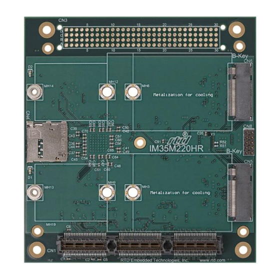
Connector Locations The following top-side photo of the IM35M220HR / IM25M220HR provides a reference for designators of the bus connectors, I/O connectors as well as their locations. PCI Connector (CN3) (if populated) Socket B (CN6) SIM 2 (Top) (CN4) Factory Use Only... -
Page 13: Attaching M.2 Modules
Two spacers are already soldered to the board for the 80mm position, and it takes the 4mm screw with no washer. Figure 6 M.2 Fasteners | www.rtd.com IM35M220HR / IM25M220HR User’s Manual RTD Embedded Technologies, Inc. -
Page 14: Functional Block Diagram
Functional Block Diagram The Figure below shows the diagram of the IM35M220HR / IM25M220HR’s dual M.2 B-Key sockets and their respective breakout and I/O connectors. The various parts of the block diagram are discussed in the following sections. PCI-104 Connector – (CN3) PCIe x1 Link M.2 B-Key (CN6) -
Page 15: Connector Functionality
PCIe Connectors (CN1 – Top, CN2 – Bottom) The IM35M220HR / IM25M220HR is a “Universal” board and can connect to either a Type 1 or Type 2 connector of a PCIe/104 or PCI-104 Express system. The position and pin assignments are compliant with the PCIe/104 Specification. (See PC/104 Specifications on page 20) PCI Connector (CN3) This connector (if populated) is used as a pass-through connector only. -
Page 16: Table 7: M.2 B-Key Pin Assignments
SIM 2 DET SIM 2 DATA PER0+ SIM 2 CLK PER0- SIM 2 RST SIM 2 PWR PET0- PE_RST PET0+ REFCLK- REFCLK+ SIM 1 DET SUSCLK 3.3V CONFIG1 3.3V 3.3V CONFIG2 | www.rtd.com IM35M220HR / IM25M220HR User’s Manual RTD Embedded Technologies, Inc. -
Page 17: Idan Connections
Weight: Approximately 0.230 Kg (0.508 lbs.) • Dimensions: 152mm L x 130 mm W x 17.0 mm H (5.98 in L x 5.12 in W x 0.67 in H) Figure 8: IDAN Dimensions | www.rtd.com IM35M220HR / IM25M220HR User’s Manual RTD Embedded Technologies, Inc. -
Page 18: Steps For Installing
11. Re-connect the power cord and apply power to the stack. 12. Boot the system and verify that all of the hardware is working properly. Figure 9: Example IDAN System | www.rtd.com IM35M220HR / IM25M220HR User’s Manual RTD Embedded Technologies, Inc. -
Page 19: Troubleshooting
If problems persist, or you have questions about configuring this product, contact RTD Embedded Technologies via the following methods: Phone: +1-814-234-8087 E-Mail: techsupport@rtd.com Be sure to check the RTD web site (http://www.rtd.com) frequently for product updates, including newer versions of the board manual and application software. | www.rtd.com IM35M220HR / IM25M220HR User’s Manual RTD Embedded Technologies, Inc. -
Page 20: Additional Information
A copy of the latest PCI and PCI Express specifications can be found on the webpage for the PCI Special Interest Group: www.pcisig.com PCI Express M.2 Specification A copy of the latest PCI Express M.2 Specification can also be found on the webpage for the PCI Special Interest Group: www.pcisig.com | www.rtd.com IM35M220HR / IM25M220HR User’s Manual RTD Embedded Technologies, Inc. -
Page 21: Limited Warranty
During the one year warranty period, RTD Embedded Technologies will repair or replace, at its option, any defective products or parts at no additional charge, provided that the product is returned, shipping prepaid, to RTD Embedded Technologies. All replaced parts and products become the property of RTD Embedded Technologies. - Page 22 RTD Embedded Technologies, Inc. 103 Innovation Boulevard State College, PA 16803 USA Telephone: 814-234-8087 Fax: 814-234-5218 www.rtd.com sales@rtd.com techsupport@rtd.com Copyright 2024 by RTD Embedded Technologies, Inc. All rights reserved.
Need help?
Do you have a question about the IM35M220HR and is the answer not in the manual?
Questions and answers