
Related Manuals for rtd ATX104HR-EXPRESS


Summary of Contents for rtd ATX104HR-EXPRESS
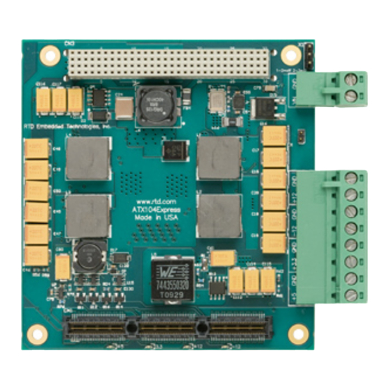
- Page 1 ATX104HR-EXPRESS High Efficiency PCI/104-Express Power Supply Module User’s Manual BDM-610020070 Rev. G...
- Page 2 User’s Manual ATX104HR-EXPRESS ATX104HR-EXPRESS Power supply module User’s Manual RTD Embedded Technologies, Inc. 103 Innovation Blvd. State College, PA 16803-0906 Phone: +1-814-234-8087 FAX: +1-814-234-5218 E-mail sales@rtd.com techsupport@rtd.com web site http://www.rtd.com ATX104HR-EXPRESS RTD Embedded Technologies, Inc.
- Page 3 11/18/2014 Added information about identifying pin one on X1 Rev G 05/18/2015 Added MTBF Published by: RTD Embedded Technologies, Inc. 103 Innovation Blvd. State College, PA 16803-0906 Copyright 1999, 2002, 2003 2004 by RTD Embedded Technologies, Inc. All rights reserved Printed in U.S.A. ATX104HR-EXPRESS RTD Embedded Technologies, Inc.
- Page 4 User’s Manual ATX104HR-EXPRESS The RTD Logo is a registered trademark of RTD Embedded Technologies. cpuModule and utilityModule are trademarks of RTD Embedded Technologies. PC/XT, PC/AT and IBM are trademarks of International Business Machines Inc. MS-DOS, Windows, Windows 95, Windows 98 and Windows NT are trademarks of Microsoft Corp. PC/104 is a registered trademark of PC/104 Consortium.
-
Page 5: Table Of Contents
Remote On/Off control............................17 Secondary +12V and -12V converters ........................18 Onboard status LED’s ............................18 Overload protection ............................18 CHAPTER 4 ATX104HR-EXPRESS SPECIFICATIONS ........... 20 Host interface ................................20 Power supply specifications ............................20 Input voltage range .............................. 20 Output Power (88W total ) .......................... - Page 6 ATX104HR-EXPRESS Figure 1: Pheonix Contact 1781043 Figure 2: Phoenix Contact 1779987 Figure 3: ATX104HR-EXPRESS powering an RTD PC/104-EXPRESS cpuModule stack. PCI bus shown with non-stack through connector. Standard is press fit stack through. Figure 4: ATX104HR-EXPRESS power supply power connections...
- Page 7 User’s Manual ATX104HR-EXPRESS ATX104HR-EXPRESS RTD Embedded Technologies, Inc.
-
Page 8: Chapter 1 Introduction
User’s Manual ATX104HR-EXPRESS NTRODUCTION Chapter 1 This user’s manual describes the operation of the ATX104HR-EXPRESS power supply unit for automotive and industrial applications. Features Some of the key features of the ATX104HR-EXPRESS include: Wide input voltage range 8-32 V DC (36V absolute max) ... -
Page 9: Mechanical Description
EMI immunity over the operating temperature range under all loads. The ATX104HR-EXPRESS can be “switched off” from a remote source. If this switch (jumper X1) is on pins 2-3 the power supply will become inactive while still powered. -
Page 10: What Comes With Your Board
(814) 234-8087. Using this manual This manual is intended to help you install your new ATX104HR-EXPRESS module and get it working quickly, while also providing enough detail about the board and its functions so that you can enjoy maximum use of its features even in the most demanding applications. -
Page 11: Chapter 2 Board Installation
OARD INSTALLATION Chapter 2 The ATX104HR-EXPRESS power supply module is very easy to connect to your industrial or automotive control system. Direct interface to PC/104-EXPRESS systems as well as EBX size boards is achieved. This chapter tells you step-by-step how to install your ATX104HR-EXPRESS into your system. -
Page 12: Installation Integrated With A Pc/104-Express Module Stack
Secure the four PC/104-EXPRESS installation holes with standoffs. Connect the board to the power supply using the power interface connectors. Figure 3: ATX104HR-EXPRESS powering an RTD PC/104-EXPRESS cpuModule stack. PCI bus shown with non-stack through connector. Standard is press fit stack through. -
Page 13: External Power Connections
User’s Manual ATX104HR-EXPRESS External power connections Pin 1 Figure 4: ATX104HR-EXPRESS power supply power connections ATX104HR-EXPRESS RTD Embedded Technologies, Inc. -
Page 14: Connector Descriptions
The output voltages are also indicated on the silk-screen on the bottom side of the module under the terminal blocks. Check these before making any external power connections. The input of the ATX104HR-EXPRESS is protected against reverse voltages, but will not withstand long term overvoltage. The transient absorbers will clip all fast disturbance and noise on the input, but may overheat if continuous overvoltage is present. -
Page 15: Chapter 3 - Hardware Description
ATX104HR-EXPRESS ARDWARE DESCRIPTION Chapter 3 This chapter describes the major features of the ATX104HR-EXPRESS, which are the following: The main +5V and +3.3V converter for the PC/104 and PC/104-EXPRESS busses The secondary power output converters +12V , –12V, 5V STDBY ... - Page 16 User’s Manual ATX104HR-EXPRESS Block diagram of the ATX104HR-EXPRESS Figure 5: ATX104HR-EXPRESS RTD Embedded Technologies, Inc.
-
Page 17: Main +5V And +3.3V Converter For The Computer
MOSFET-transistors allows operation without an additional heat-sink. Internal layers of the PCB are used to distribute heat evenly. Input circuitry of the ATX104HR-EXPRESS is protected with a 36V fast transient absorber diode and a low loss forward schottky diode. These devices are necessary to protect the input in automotive and industrial installations against fast over-voltage spikes and reverse voltage transients. -
Page 18: Secondary +12V And -12V Converters
TB3). The +12V and -12V supplies also power the PCI104-express and the PCI bus. Onboard status LED’s The ATX104HR-EXPRESS is equipped with 4 indicator LED’s. The function of the LED’s is described below. LED1 - Green. Indicates +5V power converter is operational ... - Page 19 Even though the unit can stay cooled with natural convection, enclosing the unit in a container may require heat sinking depending on the load and temperature in the container. ATX104HR-EXPRESS RTD Embedded Technologies, Inc.
-
Page 20: Chapter 4 Atx104Hr-Express Specifications
Efficiencies 5V efficiency 5V STDBY efficiency 82% 3.3V efficiency 87.6% 12V efficiency -12V efficiency 89.41% Overall Maximum Board Power dissipation (worst conditions) 13.69 Watts Output voltage regulation +-5% (max) Host bus PC/104-EXPRESS bus PC/104-Express stack-through ATX104HR-EXPRESS RTD Embedded Technologies, Inc. -
Page 21: Electromechanical
0.70 Watts @ 8V Vin 1.76 Watts @ 36V Vin Maximum power dissipated when supply is disabled 14 mWatts @ 8V Vin 135 mWatts @ 36V Vin MTPF (Environment: GB, GC - Ground Benign, Controlled at 30°C) 2,592,399 Hrs ATX104HR-EXPRESS RTD Embedded Technologies, Inc. -
Page 22: Electrical Characterization
5V Eff and Dis vs. Load 100.00% 5.000 90.00% 4.500 80.00% 4.000 70.00% 3.500 60.00% 3.000 50.00% 2.500 40.00% 2.000 30.00% 1.500 20.00% 1.000 10.00% 0.500 0.00% 0.000 Amps Max 5V Load Efficiency is 91.9% with 4.4 Watts of Dissipation. ATX104HR-EXPRESS RTD Embedded Technologies, Inc. - Page 23 -12V Eff. and Diss. vs. Load 0.800 100.00% 90.00% 0.700 80.00% 0.600 70.00% 0.500 60.00% 0.400 50.00% 40.00% 0.300 30.00% 0.200 20.00% 0.100 10.00% 0.000 0.00% Amps Max -12V Load Efficiency is 89.41% with 0.708 Watts of Dissipation. ATX104HR-EXPRESS RTD Embedded Technologies, Inc.
- Page 24 Max 3.3V Load Efficiency is 87.61% with 4.554 Watts of Dissipation. 5Vstby Eff. and Diss. vs. Load 2.500 70.00% 60.00% 2.000 50.00% 1.500 40.00% 30.00% 1.000 20.00% 0.500 10.00% 0.000 0.00% Amps Max 5Vstby Load Efficiency is 68.32% with 2.273 Watts of Dissipation. ATX104HR-EXPRESS RTD Embedded Technologies, Inc.
- Page 25 25.57 1.75 23.82 23.82 -12V 6.69 0.71 5.98 5.98 Full Load 13.69 84.59 0.86 Combined load Definition and Efficiency (Calculated). Measured at 88%. Full Load: 5V output voltage ripple P-P 20MHz BWL AC coupled. 8.8mV. ATX104HR-EXPRESS RTD Embedded Technologies, Inc.
- Page 26 User’s Manual ATX104HR-EXPRESS Full Load: 3.3V output voltage ripple P-P 20MHz BWL AC coupled. 21.4mV. ATX104HR-EXPRESS RTD Embedded Technologies, Inc.
- Page 27 User’s Manual ATX104HR-EXPRESS Full Load: 12V output voltage ripple P-P 20MHz BWL AC coupled. 12mV. ATX104HR-EXPRESS RTD Embedded Technologies, Inc.
- Page 28 User’s Manual ATX104HR-EXPRESS Full Load: -12V output voltage ripple P-P 20MHz BWL AC coupled. 16.4mV. ATX104HR-EXPRESS RTD Embedded Technologies, Inc.
- Page 29 User’s Manual ATX104HR-EXPRESS Full Load: 5VstbyV output voltage ripple P-P 20MHz BWL AC coupled. 22mV. ATX104HR-EXPRESS RTD Embedded Technologies, Inc.
- Page 30 User’s Manual ATX104HR-EXPRESS 10 to 90%: 5V output step response 20MHz BWL AC coupled. ATX104HR-EXPRESS RTD Embedded Technologies, Inc.
- Page 31 User’s Manual ATX104HR-EXPRESS 10 to 90%: 5Vstby output step response 20MHz BWL AC coupled. ATX104HR-EXPRESS RTD Embedded Technologies, Inc.
- Page 32 User’s Manual ATX104HR-EXPRESS 10 to 90%: 3.3V output step response 20MHz BWL AC coupled. ATX104HR-EXPRESS RTD Embedded Technologies, Inc.
- Page 33 User’s Manual ATX104HR-EXPRESS 10 to 90%: 12V output step response 20MHz BWL AC coupled. ATX104HR-EXPRESS RTD Embedded Technologies, Inc.
- Page 34 User’s Manual ATX104HR-EXPRESS 10 to 90%: -12V output step response 20MHz BWL AC coupled. ATX104HR-EXPRESS RTD Embedded Technologies, Inc.
- Page 35 Input surge protection. Hard step input from 0V to 36V through 3 foot power leads. The inductive spike is over 71.6V. The board never sees anything above 36V. The startup is 10.5msec with full load ATX104HR-EXPRESS RTD Embedded Technologies, Inc.
-
Page 36: Chapter 5 Return Policy And Warranty
We will not ship by next-day service without your pre-approval. Carefully package the product, using proper anti-static packaging. Write the RMA number in large (1") letters on the outside of the package. Return the package to: RTD Embedded Technologies, Inc. 103 Innovation Blvd. State College PA 16803-0906 ATX104HR-EXPRESS... - Page 37 User’s Manual ATX104HR-EXPRESS ATX104HR-EXPRESS RTD Embedded Technologies, Inc.
-
Page 38: Chapter 6 Limited Warranty
During the one year warranty period, RTD Embedded Technologies will repair or replace, at its option, any defective products or parts at no additional charge, provided that the product is returned, shipping prepaid, to RTD Embedded Technologies. All replaced parts and products become the property of RTD Embedded Technologies. -
Page 39: Chapter 7 Atx104Hrtx-Express-88W Dimensioned Drawing
User’s Manual ATX104HR-EXPRESS ATX104HRTX-E -88W D XPRESS IMENSIONED RAWING Chapter 7 Figure 6: Dimensioned Drawing ATX104HR-EXPRESS RTD Embedded Technologies, Inc. -
Page 40: Chapter 8 Idan-Atx104Hrtx-Express-88Ws Drawing And Pinouts
User’s Manual ATX104HR-EXPRESS IDAN-ATX104HRTX-E -88WS D XPRESS RAWING AND Chapter 8 INOUTS ATX104HR-EXPRESS RTD Embedded Technologies, Inc. - Page 41 User’s Manual ATX104HR-EXPRESS ATX104HR-EXPRESS RTD Embedded Technologies, Inc.
- Page 42 User’s Manual ATX104HR-EXPRESS ATX104HR-EXPRESS RTD Embedded Technologies, Inc.
- Page 43 User’s Manual ATX104HR-EXPRESS RTD Embedded Technologies, Inc. 103 Innovation Blvd. State College PA 16803-0906 Our website: www.rtd.com ATX104HR-EXPRESS RTD Embedded Technologies, Inc.
Need help?
Do you have a question about the ATX104HR-EXPRESS and is the answer not in the manual?
Questions and answers