
Related Manuals for rtd DM5856HR


Summary of Contents for rtd DM5856HR
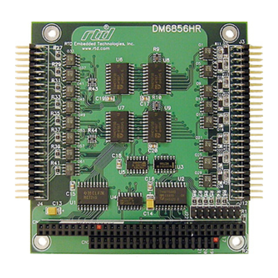
- Page 1 DM5856HR/DM6856HR Isolated digital I/O-module User’s Manual Hardware Revision 1.0 B...
- Page 2 User’s Manual DM5856HR/DM6856HR I/O- SOLATED DIGITAL MODULE User’s Manual REAL TIME DEVICES FINLAND OY LEPOLANTIE 14 FIN-00660 HELSINKI FINLAND Phone: (+358) 9 346 4538 FAX: (+358) 9 346 4539 E-Mail sales@rtdfinland.fi Website www.rtdfinland.fi DM5856HR/DM6856HR RTD Finland Oy...
- Page 3 RTD Finland Oy also reserves the right to alter the contents of this manual, as well as features and specifications of this product at any time, without prior notice.
-
Page 4: Table Of Contents
Programming the DM5856/DM6856................20 Clearing and setting bits in a port..................20 Isolated output programming ..................21 Isolated input programming .................... 21 CHAPTER 6 - DM5856/DM6856 SPECIFICATIONS ......22 CHAPTER 7 - RETURN POLICY & WARRANTY ......23 DM5856HR/DM6856HR RTD Finland Oy... -
Page 5: List Of Illustrations & Tables
List of Illustrations & Tables Illustrations Fig. 2-1: Board layout showing jumper locations Fig. 3-1: DM5856HR/DM6856HR integrated in a PC/104 dataModule stack Fig. 3-2: 19” Eurocard rack installation with an integrated PC/104 data Module and EUROCARD cpuModule computer system Fig. 3-3: Input connection for Channel number 1 Fig. -
Page 6: Chapter 1 - Introduction
Mechanical description The DM5856HR is designed on a PC/104 form factor. An easy mechanical interface to both PC/104 and EUROCARD systems can be achieved. Stack your PC/104 compatible computer directly on the DM5856HR using the onboard mounting holes. -
Page 7: What Comes With Your Board
(+358) 9 346 4538. Board accessories In addition to the items included in your DM5856HR delivery, several software and hardware accessories are available. Contact your distributor for more information and for advice on selecting the most appropriate accessories to support your instrumentation system. -
Page 8: Chapter 2 - Board Settings
OARD SETTINGS Chapter 2 The DM5856HR/DM6856HR Isolated digital I/O board has jumper settings which can be changed to suit your application. It is factory configured with a +5V input range configuration. The factory settings are listed and shown in the diagram in the beginning of this chapter. -
Page 9: Factory-Configured Jumper Settings
User’s Manual Factory-Configured Jumper Settings Table 2-1 below illustrates the factory jumper setting for the DM5856HR/DM6856HR. It also shows the board layout of the DM5856HR/DM5856HR and the locations of the jumpers. The following paragraphs explain how to change the factory jumper settings to suit your specific application. -
Page 10: Base Address Jumpers
When the jumper is removed it corresponds to a logical "0", connecting the jumper to a "1". When you set the base address of the module, record the setting inside the back cover of this manual (directly after the Appendices). DM5856HR/DM6856HR RTD Finland Oy... - Page 11 User’s Manual BASE ADDRESS JUMPER SETTINGS FOR DM5856HR/DM6858 BOARDS Base address Jumper Settings Base Address Jumper settings Hex / (Decimal) 8 7 6 5 4 3 2 1 Hex / (Decimal) 8 7 6 5 4 3 2 1 200 / (512)
-
Page 12: Chapter 3 - Board Installation
OARD INSTALLATION Chapter 3 The DM5856HR/DM6856HR Isolated Digital Interface board is very easy to connect to your industrial or automotive control system. Direct interface to PC/104 systems as well as EUROCARD boards is possible. This chapter gives step-by-step instructions on how to install the board into your system. - Page 13 The PC/104 system can easily be inserted into a 19" rack installation using the CPU as a "form factor adapter". Assemble your PC/104 data modules on a RTD single board EUROCARD computer and install the system in a 19" enclosure. Multiple DM5856HR boards can be easily connected to this system. See figure 3-2 below.
-
Page 14: External I/O Connections
- IN8 + IN9 -IN9 +IN10 - IN10 + IN11 -IN11 +IN12 - IN12 + IN13 -IN13 +IN14 - IN14 + IN15 -IN15 +IN16 - IN16 Fig: 3-3: This diagram illustrates the input connection for channel 1 DM5856HR/DM6856HR RTD Finland Oy... - Page 15 Out8 GND-8 +Vsupply-9 Out9 GND-9 +Vsupply-10 Out10 GND-10 +Vsupply-11 Out11 GND-11 +Vsupply-12 Out12 GND-12 +Vsupply-13 Out13 GND-13 +Vsupply-14 Out14 GND-14 +Vsupply-15 Out15 GND-15 +Vsupply-16 Out16 GND-16 3-4: This diagram illustrates the output connection for channel 1 DM5856HR/DM6856HR RTD Finland Oy...
-
Page 16: Chapter 4 - Hardware Description
User’s Manual ARDWARE DESCRIPTION Chapter 4 This chapter describes in detail the two major features of the DM5856HR/DM6856HR: The isolated optocoupler inputs and the isolated optocoupler outputs. Fig 4-1: DM5856HR/DM6856HR Block diagram DM5856HR/DM6856HR RTD Finland Oy... -
Page 17: Isolated Digital Inputs
User’s Manual Isolated digital inputs The Isolated output stage of the DM5856HR consists of two major parts: 1. Optocouplers 2. Input latch 1. Optocouplers Small SMD-optocouplers are used to isolate each channel of the isolated inputs. Individual optocouplers are used for each channel. The optocouplers are directly connected to the input latch in an inverting configuration. -
Page 18: Isolated Digital Outputs
User’s Manual Isolated digital outputs The Isolated input stage of the DM5856HR/DM6856HR consists of two major parts: 1. Optocouplers 2. Output registers 1. Optocouplers Small SMD-optocouplers are used to isolate each channel of the isolated outputs. Individual optocouplers are used for each channel. The optocouplers are directly connected to the Output latch. -
Page 19: Chapter 5 - Board Operation And Programming
Defining the I/O Map The I/O map of the DM5856HR/DM6856HR is shown in Table 5-1 below. As shown, the module occupies two addresses. The Base Address (designated as BA) can be set using the jumpers as described in Chapter 2 (Board settings). The following sections describe the register contents of each address used in the I/O map. -
Page 20: Base+0 I/O Register 1 (Read/Write) -Base+1 I/O Register 2 (Read/Write) Programming The Dm5856/Dm6856
This section gives you some general information about programming the DM5856HR board. It then walks you through the major programming functions of the DM5856HR. This will help you use the example program that is included with the board. All of the program descriptions use decimal values unless otherwise specified. -
Page 21: Isolated Output Programming
The optoisolated inputs are read from a data latch. These inputs can be interrogated in the following ways (examples in "C" syntax): Software controlled byte read low_data = inp(BA); high_data = inp(BA+1); Software controlled direct word read word_data = inpw(BA); DM5856HR/DM6856HR RTD Finland Oy... -
Page 22: Chapter 6 - Dm5856/Dm6856 Specifications
User’s Manual - DM5856HR/DM6856HR S PECIFICATIONS Chapter 6 Host Interface Jumper selectable base address, I/O mapped Digital Outputs (isolated) Number of lines Isolation voltage 1.500V Rms Output stage Open collector with a 4,8K pull-up 8 mA sink current, 30V Output supply voltage... -
Page 23: Chapter 7 - Return Policy & Warranty
8) Carefully package the product to be returned using anti-static packaging! We will not be responsible for products damaged in transit for repair. 7) Write the RMA number on the outside of the package. 8) Ship the package to: Real Time Devices Finland Oy Lepolantie 14 FIN-00660 Helsinki FINLAND DM5856HR/DM6856HR RTD Finland Oy... - Page 24 LIMITATIONS ON HOW LONG AN IMPLIED WARRANTY LASTS, SO THE ABOVE LIMITATIONS OR EXCLUSIONS MAY NOT APPLY TO YOU. THIS WARRANTY GIVES YOU SPECIFIC LEGAL RIGHTS, AND YOU MAY ALSO HAVE OTHER RIGHTS, WHICH VARY FROM STATE TO STATE. DM5856HR/DM6856HR RTD Finland Oy...
Need help?
Do you have a question about the DM5856HR and is the answer not in the manual?
Questions and answers