
Related Manuals for rtd DM35424HR


Summary of Contents for rtd DM35424HR
- Page 1 DM35424HR/DM35224HR PCI Express Analog I/O dataModule User’s Manual BDM-610010044 Rev. E RTD Embedded Technologies, Inc. AS9100 and ISO 9001 Certified...
- Page 2 RTD Embedded Technologies, Inc. 103 Innovation Boulevard State College, PA 16803 USA Telephone: 814-234-8087 Fax: 814-234-5218 www.rtd.com sales@rtd.com techsupport@rtd.com...
- Page 3 Failure to follow the instructions found in this manual may result in damage to the product described in this manual, or other components of the system. The procedure set forth in this manual shall only be performed by persons qualified to service electronic equipment. Contents and specifications within this manual are given without warranty, and are subject to change without notice. RTD Embedded Technologies, Inc. shall not be liable for errors or omissions in this manual, or for any loss, damage, or injury in connection with the use of this manual.
-
Page 4: Table Of Contents
DIO Connectors - 15-pin “D” Female Connector Steps for Installing ..................................29 Functional Description DMA Engine ....................................30 Analog Front-End ..................................30 DAC Loopback Mode Single-Ended Positive Input Mode Single-Ended Negative Input Mode Differential Input Mode | www.rtd.com DM35424/DM35224 User’s Manual RTD Embedded Technologies, Inc. - Page 5 POST_STOP_CAPTURE (Read/Write) 6.3.12 SAMPLE_CNT (Read Only) 6.3.13 INT_ENA (Maskable Read/Write) 6.3.14 INT_STAT (Read/Clear) 6.3.15 CLK_BUSn 6.3.16 AD_CONFIG (Maskable Read/Write) 6.3.17 CHn_FRONT_END_CONFIG (Maskable Read/Write) 6.3.18 CHn_FIFO_DATA_CNT (Read) 6.3.19 CHn_FILTER (Read/Write) 6.3.20 CHn_INT_STAT (Read/Clear) | www.rtd.com DM35424/DM35224 User’s Manual RTD Embedded Technologies, Inc.
- Page 6 BAR2 – Temperature Sensor Functional Block ........................52 6.7.1 FB_ID (Read-Only) 6.7.2 FB_DMA_CHANNELS (Read -Only) 6.7.3 FB_DMA_BUFFERS (Read-Only) 6.7.4 TEMPERATURE_VAL (Read Only) Troubleshooting Additional Information PC/104 Specifications ................................54 PCI and PCI Express Specification ............................54 Limited Warranty | www.rtd.com DM35424/DM35224 User’s Manual RTD Embedded Technologies, Inc.
- Page 7 Table 23: Multi-Channel DAC Functional Block ..............................46 Table 24: Digital I/O Functional Block..................................50 Table 25: Digital Potentiometer Functional Block ..............................51 Table 26: Temperature Sensor Functional Block ..............................52 | www.rtd.com DM35424/DM35224 User’s Manual RTD Embedded Technologies, Inc.
-
Page 8: Introduction
This board is targeted to sensors that require high precision with a low signal level, such as accelerometers, pressure transducers, and Resistance Temperature Detectors (RTD). The DAC output can provide sufficient current and voltage for the excitation voltage of most sensors. -
Page 9: Contact Information
The Intelligent Data Acquisition Node (IDAN™) building block can be used in just about any combination with other IDAN building blocks to create a simple but rugged 104™ stack. This module can also be incorporated in a custom-built RTD HiDAN™ or HiDANplus High Reliability Intelligent Data Acquisition Node. -
Page 10: Specifications
Settling Time Complete Settling Samples Delay High-Resolution Mode Samples All other modes ENOB High-Resolution Mode 15.18 Bits All other modes 15.04 High-Resolution Mode 91.92 All other modes 91.13 High-Resolution Mode -83.78 | www.rtd.com DM35424/DM35224 User’s Manual RTD Embedded Technologies, Inc. - Page 11 Change from 0x0 – 0xFF µs Write to Nonvolatile Read Nonvolatile µs Write to Output µs Calculated with Input = -1.2 dbFS @ 1 KHz, Max Sample Rate Calculated with Inputs grounded, Max Sample Rate | www.rtd.com DM35424/DM35224 User’s Manual RTD Embedded Technologies, Inc.
-
Page 12: Analog Input Fft Plots
Blackman-Hanning three term window. Three samples were taken, and the FFT data averaged. -100 -120 -140 Frequency (MHz) Figure 1: High Speed Mode FFT -100 -120 -140 Frequency (kHz) Figure 2: High Resolution Mode FFT | www.rtd.com DM35424/DM35224 User’s Manual RTD Embedded Technologies, Inc. -
Page 13: Board Connection
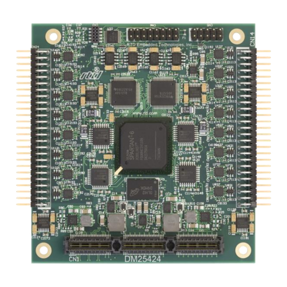
Physical Characteristics • Weight: Approximately 80 g (0.18 lbs.) • Dimensions: 90.17 mm L x 95.89 mm W (3.550 in L x 3.775 in W) Figure 3: Board Dimensions | www.rtd.com DM35424/DM35224 User’s Manual RTD Embedded Technologies, Inc. -
Page 14: Connectors And Jumpers
FCI 65043-027LF (or similar) cut-to-fit. Pin 1 is indicated by a square solder pad on the board. Table 4: CN6 Digital I/O Pin Assignments PORT0_1 PORT0_0 PORT0_3 PORT0_2 PORT0_5 PORT0_4 PORT0_7 PORT0_6 PORT0_9 PORT0_8 PORT0_11 PORT0_10 PORT0_13 PORT0_12 | www.rtd.com DM35424/DM35224 User’s Manual RTD Embedded Technologies, Inc. -
Page 15: Analog I/O Connectors: Cn14 And Cn24
FCI 65043-027LF (or similar) cut-to-fit. Pin 1 is indicated by a square solder pad on the board. Table 7: CN6 Digital I/O Pin Assignments PORT0_1 PORT0_0 PORT0_3 PORT0_2 PORT0_5 PORT0_4 PORT0_7 PORT0_6 PORT0_9 PORT0_8 PORT0_11 PORT0_10 PORT0_13 PORT0_12 | www.rtd.com DM35424/DM35224 User’s Manual RTD Embedded Technologies, Inc. -
Page 16: Analog I/O Connectors: Cn14
ADC0 Channel 6+ AGND AGND AGND DAC1 Channel 3 ADC0 Channel 7- ADC0 Channel 7+ AGND AGND Note: CN3 is for Factory Use only 3.3.4 UMPERS There are no jumpers on the DM35424. | www.rtd.com DM35424/DM35224 User’s Manual RTD Embedded Technologies, Inc. -
Page 17: Steps For Installing
10. Attach any necessary cables to the PC/104 stack. 11. Re-connect the power cord and apply power to the stack. 12. Boot the system and verify that all of the hardware is working properly. Figure 5: Example 104™Stack | www.rtd.com DM35424/DM35224 User’s Manual RTD Embedded Technologies, Inc. -
Page 18: Idan Connections
Weight: Approximately 0.35 Kg (0.78 lbs.) • Dimensions: 152 mm L x 130 mm W x 34 mm H (5. in L x 5.12 in W x 1.34 in H) Figure 6: DM35424 IDAN Dimensions | www.rtd.com DM35424/DM35224 User’s Manual RTD Embedded Technologies, Inc. -
Page 19: Dm35224 Physical Characteristics
Weight: Approximately 0.22 Kg (0.48 lbs.) • Dimensions: 152 mm L x 130 mm W x 17 mm H (5. in L x 5.12 in W x 0.67 in H) Figure 7: IDAN Dimensions | www.rtd.com DM35424/DM35224 User’s Manual RTD Embedded Technologies, Inc. -
Page 20: Connectors
Connectors 4.4.1 DM35424 E I/O C XTERNAL ONNECTORS AIO 1-8 Connector - 68-pin Subminiature “D” Female Connector (SCSI type) | www.rtd.com DM35424/DM35224 User’s Manual RTD Embedded Technologies, Inc. -
Page 21: Table 9: Idan- Dm35424 68-Pin Subminiature "D" Connector
The 68-pin connector is a SCSI type connector. The pinout in the table above differs from the industry standard SCSI pin-out. Note: in the IDAN image on the previous page, SCSI pin 2 is positioned below pin 1. | www.rtd.com DM35424/DM35224 User’s Manual RTD Embedded Technologies, Inc. -
Page 22: Aio 5-16 Connector - 68-Pin Subminiature "D" Female Connector
ADC1 Channel 3- CN24 CN24 AGND CN24 AGND CN24 DAC3 Channel 0 CN24 AGND CN24 ADC1 Channel 4+ CN24 ADC1 Channel 4- CN24 AGND CN24 AGND CN24 DAC3 Channel 1 CN24 AGND | www.rtd.com DM35424/DM35224 User’s Manual RTD Embedded Technologies, Inc. -
Page 23: Aio 1-8 Connector - 62-Pin High Density "D" Female Connector
ADC0 Channel 6- CN14 AGND CN14 DAC1 Channel 3 CN14 ADC0 Channel 2+ CN14 ADC0 Channel 7- CN14 AGND Reserved CN14 ADC0 Channel 3+ Reserved CN14 AGND Reserved CN14 ADC0 Channel 4+ Reserved | www.rtd.com DM35424/DM35224 User’s Manual RTD Embedded Technologies, Inc. -
Page 24: Aio 5-16 Connector - 62-Pin High Density "D" Female Connector
ADC1 Channel 6- CN24 AGND CN24 DAC3 Channel 3 CN24 ADC1 Channel 2+ CN24 ADC1 Channel 7- CN24 AGND Reserved CN24 ADC1 Channel 3+ Reserved CN24 AGND Reserved CN24 ADC1 Channel 4+ Reserved | www.rtd.com DM35424/DM35224 User’s Manual RTD Embedded Technologies, Inc. -
Page 25: Dio Connectors - 15-Pin "D" Female Connector
Sample Mating Connector: Amp 1658611-3 Table 13: IDAN- DM35424 15-Pin "D" Connector IDAN Pin# Signal DM35424 Pin # PORT0_0 PORT0_2 PORT0_4 PORT0_6 PORT0_8 PORT0_10 PORT0_12 PORT0_1 PORT0_3 PORT0_5 PORT0_7 PORT0_9 PORT0_11 PORT0_13 | www.rtd.com DM35424/DM35224 User’s Manual RTD Embedded Technologies, Inc. -
Page 26: Dm35224 External I/O Connectors
ADC0 Channel 3- CN14 AGND CN14 AGND CN14 DAC1 Channel 0 CN14 AGND CN14 ADC0 Channel 4+ CN14 ADC0 Channel 4- CN14 AGND CN14 AGND CN14 DAC1 Channel 1 CN14 AGND | www.rtd.com DM35424/DM35224 User’s Manual RTD Embedded Technologies, Inc. -
Page 27: Aio 1-8 Connector - 62-Pin High Density "D" Female Connector
ADC0 Channel 6- CN14 AGND CN14 DAC1 Channel 3 CN14 ADC0 Channel 2+ CN14 ADC0 Channel 7- CN14 AGND Reserved CN14 ADC0 Channel 3+ Reserved CN14 AGND Reserved CN14 ADC0 Channel 4+ Reserved | www.rtd.com DM35424/DM35224 User’s Manual RTD Embedded Technologies, Inc. -
Page 28: Dio Connectors - 15-Pin "D" Female Connector
Sample Mating Connector: Amp 1658611-3 Table 16: IDAN- DM35424 15-Pin "D" Connector DM35424 Pin # IDAN Pin# Signal PORT0_0 PORT0_2 PORT0_4 PORT0_6 PORT0_8 PORT0_10 PORT0_12 PORT0_1 PORT0_3 PORT0_5 PORT0_7 PORT0_9 PORT0_11 PORT0_13 | www.rtd.com DM35424/DM35224 User’s Manual RTD Embedded Technologies, Inc. -
Page 29: Steps For Installing
10. Attach any necessary cables to the IDAN system. 11. Re-connect the power cord and apply power to the stack. 12. Boot the system and verify that all of the hardware is working properly. Figure 8: Example IDAN System | www.rtd.com DM35424/DM35224 User’s Manual RTD Embedded Technologies, Inc. -
Page 30: Functional Description
The DM35424 analog front-end consist of two filters and a differential programmable gain amplifier, PGA. The two filters are, one RF filter with a 3dB cutoff frequency of 1MHZ and the second filter is a single-pole pass filter with a 3dB cutoff frequency of 64KHz. Refer to Figure 10 for analog front-end design. | www.rtd.com DM35424/DM35224 User’s Manual RTD Embedded Technologies, Inc. -
Page 31: Dac Loopback Mode
80Ω 100pF Figure 10: DM35424 Front-End Note: For custom cutoff frequency for front-end filter contact RTD Sales. The DM35424 also features four input modes. These modes can be selected by using the CHn_FRONT_END_CONFIG (Maskable Read/Write) register of the ADC on page 43. A description of each mode can be found below. -
Page 32: Single-Ended Positive Input Mode
There are several steps to initialize the Analog to Digital converter. The initialization prepares the converter and the front-end to capture samples. Following the example programs and using the drivers provided by RTD will ensure that these steps are followed in the correct order. -
Page 33: Data Formatting
The DM35424 has an adjustable voltage reference controlled by a digital potentiometer. This allows the voltage references that are used for the ADC’s and DAC’s to be adjusted by ±0.5%. By adjusting the reference to a partially ADC or DAC, you can correct the gain error of the device. | www.rtd.com DM35424/DM35224 User’s Manual RTD Embedded Technologies, Inc. -
Page 34: Register Address Space
Channel Threshold Inverted– All of the channels are within the High and Low threshold. 0x0A: CLK_BUS2 Inverted 0x0B: CLK_BUS3 Inverted 0x0C: CLK_BUS4 Inverted 0x0D: CLK_BUS5 Inverted 0x0E: CLK_BUS6 Inverted 0x0F: CLK_BUS7 Inverted | www.rtd.com DM35424/DM35224 User’s Manual RTD Embedded Technologies, Inc. -
Page 35: Bar0 - General Board Control
This register contains the format ID that is used in this board. The current value is 0x01. 6.1.5 GBC_PDP (R This register contains the PDP number for this board. 6.1.6 GBC_BUILD (R This register contains a unique 32-bit build number for the FPGA code. | www.rtd.com DM35424/DM35224 User’s Manual RTD Embedded Technologies, Inc. -
Page 36: Gbc_Sys_Clk_Freq (Read Only)
This is the offset from the beginning of the Functional Block section in BAR2 that this Functional Block resides in. 6.1.12 FB _DMA (R FFSET This is the offset from the beginning of the Functional Block section in BAR2 that the Functional Block DMA Registers reside in. | www.rtd.com DM35424/DM35224 User’s Manual RTD Embedded Technologies, Inc. -
Page 37: Bar2 - Functional Block Standard Dma
The user may also write a value to this register and then poll the register to see when the value changes. This method can be used to detect when the DMA engine services the channel without an Action change. | www.rtd.com DM35424/DM35224 User’s Manual RTD Embedded Technologies, Inc. -
Page 38: Fb_Dmam_Setup (Read/Write)
B[9:0] This is the amount of space available in the write FIFO in bytes. Software can use this to determine when the FIFO is full. A value of 0x3FC indicated that there are 1020 or more bytes of space available. B15: WR_FULL- ‘1’ indicates that the write FIFO is full | www.rtd.com DM35424/DM35224 User’s Manual RTD Embedded Technologies, Inc. -
Page 39: Fb_Dmam_Addressn (Read/Write)
The DMA engine will set the error bit and PAUSE if it is ready to use this descriptor and the Used bit is set, unless the IgnoreUsed bit is set. The bits are cleared by writing 0x00 to the byte. | www.rtd.com DM35424/DM35224 User’s Manual RTD Embedded Technologies, Inc. -
Page 40: Bar2 - Adc Functional Block
FB + 0xC0 CH5_LAST_SAMPLE FB + 0xC4 CH6_FRONT_END_CONFIG (Maskable register – 16-bit) FB + 0xC8 CH6_FIFO_DATA_CNT FB + 0xCC CH6_INT_ENA CH6_INT_STAT CH6_FILTER Reserved FB + 0xD0 CH6_THRESH_HIGH FB + 0xD4 CH6_THRESH_LOW | www.rtd.com DM35424/DM35224 User’s Manual RTD Embedded Technologies, Inc. -
Page 41: Fb_Id (Read-Only)
0x05: Wait to re-arm – Waiting until local FIFO is empty so the pre-trigger buffer can be filled. 0x07: Done capturing 6.3.5 CLK_SRC (R RITE Selects the source for CLK_DIV from the clock bus. Refer to Clock Source on page 34 for list of valid values. | www.rtd.com DM35424/DM35224 User’s Manual RTD Embedded Technologies, Inc. -
Page 42: Start_Trig (Read/Write)
B6: Sampling has completed and the FIFO is empty (all data transferred to host) B7: Pacer – The pacer clock has ticked. 6.3.15 CLK_BUS NOTE: If a CLK_BUS is unassigned in all function blocks, it defaults to System Clock/Immediate. | www.rtd.com DM35424/DM35224 User’s Manual RTD Embedded Technologies, Inc. -
Page 43: Ad_Config (Maskable Read/Write)
± 1.25 V 1.25 - 3.75 V ± 625 mV 1.875 - 3.125V ± 312.5 mV 2.1875 - 2.8125V ± 156.25 mV 2.34375 - 2.65625 V ± 78.125 mV 2.421875 - 2.578125V | www.rtd.com DM35424/DM35224 User’s Manual RTD Embedded Technologies, Inc. -
Page 44: Chn_Filter (Read/Write)
Figure 11: Filter Response with each ORDER Value ORDER -3 dB Cutoff 0.114791 * f 0.045995 * f 0.021236 * f 0.010255 * f 0.005042 * f 0.002501 * f 0.001246 * f | www.rtd.com DM35424/DM35224 User’s Manual RTD Embedded Technologies, Inc. -
Page 45: Chn_Int_Stat (Read/Clear)
ADC range unexpected results will occur. 6.3.24 CH_LAST_SAMPLE (R The last sample read from the ADC Converter, after filtering. This is the same value that is written to the DMA FIFO. | www.rtd.com DM35424/DM35224 User’s Manual RTD Embedded Technologies, Inc. -
Page 46: Bar2 - Dac Functional Block
0x04 – Uninitialized. This is the power-on state. No converter initialization has taken place. Sampling is stopped, and all counters are reset and the triggering state machine is reset. Transition to any of the other Modes will start converter initialization (sampling will not start until initialization is complete). | www.rtd.com DM35424/DM35224 User’s Manual RTD Embedded Technologies, Inc. -
Page 47: Clk_Src (Read/Write)
This is useful when using a slow sample clock. 6.4.10 POST_STOP_CONVERSIONS (R RITE Number of conversions to send after the Stop Trigger. 6.4.11 CONVERSION_CNT (R Total number of conversions. It also continues counting after a Re-Arm. | www.rtd.com DM35424/DM35224 User’s Manual RTD Embedded Technologies, Inc. -
Page 48: Int_Ena (Maskable Read/Write)
DAC. This allows an automated indication to the application software as to the state of the data being sent to the DAC. Marker bit 7 corresponds to bit 31 of the DAC data, and Marker bit 0 corresponds to bit 24 of the DAC data. | www.rtd.com DM35424/DM35224 User’s Manual RTD Embedded Technologies, Inc. -
Page 49: Int_Ena (Read/Write)
The last value sent to the DAC Converter. If the current Mode is “Reset” or the associated DMA engine is set to “Clear”, a write to this register will immediately update the DAC Converter. | www.rtd.com DM35424/DM35224 User’s Manual RTD Embedded Technologies, Inc. -
Page 50: Bar2 - Digital I/O Functional Block
The value to be output if the pins are configured as output. Bit assignments are the same as above. 6.5.6 DIO_DIRECTION (R RITE Selects the direction of the I/O bit. 0=input, 1=output. Bit assignments are the same as above. During power up Digital I/O defaults to inputs. | www.rtd.com DM35424/DM35224 User’s Manual RTD Embedded Technologies, Inc. -
Page 51: Bar2 - Reference Adjustment Digital Potentiometer Functional Block
Copy ADC adjustment nonvolatile memory to volatile memory 0x3200: Copy DAC adjustment nonvolatile memory to volatile memory 0x3300: Copy Both nonvolatile memory to volatile memory XX: is the data value range (0x0 – 0xFF) | www.rtd.com DM35424/DM35224 User’s Manual RTD Embedded Technologies, Inc. -
Page 52: Bar2 - Temperature Sensor Functional Block
This register is updated every second. ���������������������� = ���������������� ���������� ∗ 0.0078125 �� Temperature (ºC) Register Value 0x3E80 0x0C80 0.0625 0x0008 0x0000 -0.0625 0xFFF8 0xF380 0xE480 | www.rtd.com DM35424/DM35224 User’s Manual RTD Embedded Technologies, Inc. -
Page 53: Troubleshooting
If problems persist, or you have questions about configuring this product, contact RTD Embedded Technologies via the following methods: Phone: +1-814-234-8087 E-Mail: techsupport@rtd.com Be sure to check the RTD web site (http://www.rtd.com) frequently for product updates, including newer versions of the board manual and application software. | www.rtd.com DM35424/DM35224 User’s Manual RTD Embedded Technologies, Inc. -
Page 54: Additional Information
A copy of the latest PC/104 specifications can be found on the webpage for the PC/104 Embedded Consortium: www.pc104.org PCI and PCI Express Specification A copy of the latest PCI and PCI Express specifications can be found on the webpage for the PCI Special Interest Group: www.pcisig.com | www.rtd.com DM35424/DM35224 User’s Manual RTD Embedded Technologies, Inc. -
Page 55: Limited Warranty
During the one year warranty period, RTD Embedded Technologies will repair or replace, at its option, any defective products or parts at no additional charge, provided that the product is returned, shipping prepaid, to RTD Embedded Technologies. All replaced parts and products become the property of RTD Embedded Technologies. - Page 56 RTD Embedded Technologies, Inc. 103 Innovation Boulevard State College, PA 16803 USA Telephone: 814-234-8087 Fax: 814-234-5218 www.rtd.com sales@rtd.com techsupport@rtd.com Copyright 2023 by RTD Embedded Technologies, Inc. All rights reserved.
Need help?
Do you have a question about the DM35424HR and is the answer not in the manual?
Questions and answers