Table of Contents
Advertisement
Quick Links
Advertisement
Table of Contents

Related Manuals for IWILL mP4G2 Series


Summary of Contents for IWILL mP4G2 Series
- Page 1 Iwill mP4G2 Series Motherboard User’s Manual mP4G2 Series Version 1.0...
- Page 2 Series Motherboard User’s Manual...
- Page 3 Preface FCC Compliance Statement This equipment has been tested and found to comply with limits for a Class B digital device, pursuant to Part 15 of the FCC rules. These limits are designed to provide reasonable protection against harmful interference in residential installations.
- Page 4 Series Motherboard Disclaimer The information in this document is subject to change without notice. The manufacturer makes no representa- tions or warranties regarding the contents of this manual and specifically disclaims any implied warranties of merchantability or fitness for any particular purpose.
-
Page 5: Table Of Contents
Preface Table of Contents 1: Introduction ............1-1 About This Manual ............1-2 Package Contents ............. 1-2 2: Hardware Configuration ........2-1 Components ..............2-1 Connectors ................ 2-1 Jumpers ................2-1 External I/O Ports .............. 2-1 Motherboard Layout ............2-2 Motherboard Layout Key ........... - Page 6 Integrated Peripherals Screen ........... 4-5 Power Management Setup Screen ........4-6 PnP/PCI Configurations ............ 4-7 PC Health Status ............... 4-8 IWILL Smart Setting ............4-8 Load Fail-Safe Defaults ............. 4-9 Load Optimized Defaults ..........4-10 Setting Supervisor/User Password ........4-10 Save &...
- Page 7 Preface 5: Drivers and Utilities ..........5-1 Running the Power Installer Disc ........5-1 Drivers and Utilities Screen ..........5-2 Drivers Installation Screen ..........5-3 Software Utility Screen ............5-4 Make Driver Screen ............5-5 6: Specifications ............6-1 mP4G2 Motherboard ............6-1 mP4G2S Motherboard ............
- Page 8 Series Motherboard User’s Manual viii...
-
Page 9: 1: Introduction
200/266 MHz DDR SDRAM (mP4G2) or 100 MHz SDRAM (mP4G2S) using two DIMM memory sockets. Two 32-bit PCI slots provide expansion flexibility. The mP4G2 Series motherboard uses the latest Intel 845GV chipset (mP4G2) or 845GL chipset (mP4G2S) to integrate all system control functions. -
Page 10: About This Manual
6. Specifications, lists the technical specifications of the motherboard. Package Contents The motherboard package should contain the following items: • mP4G2 Series motherboard • IDE connector cables • Floppy Disk Drive connector cables • Three spare Jumper caps • Power Installer software & utilities disc •... -
Page 11: 2: Hardware Configuration
Chapter 2 Hardware Configuration 2: Hardware Configuration This chapter describes the motherboard layout and shows the location, function, and configuration of key compo- nents, including sockets, slots, connectors and jumpers as well as the external I/O ports. Before installing this motherboard read the following pages carefully for location and function of these items. -
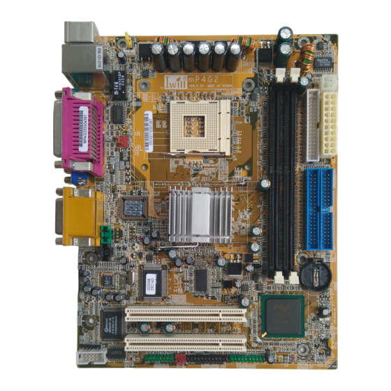
Page 12: Motherboard Layout
Series Motherboard Motherboard Layout The location of motherboard components is shown below. mP4G2 WOL1 ATX2x2 DDR1 DDR2 IDE1 IDE2 IDE2 AC'97 Codec ALC650 PCI1 INTEL 82801DB PCI2 COM2 User’s Manual 2 - 2... -
Page 13: Motherboard Layout Key
Chapter 2 Hardware Configuration Motherboard Layout Key These components, connectors and jumpers are located in the motherboard layout graphic on the facing page. Component Function CPU1 mPGA478 CPU socket ATX, ATX 2x2 Power connectors for ATX power supply DDR1, DDR2 DIMM memory sockets for DDR SDRAM modules (mP4G2 version) SDR1, SDR2... -
Page 14: Jp1: Clear Cmos Jumper
Series Motherboard JP1: Clear CMOS Jumper This jumper switch, JP1, clears the CMOS Setup con- figuration that is stored in the real-time clock’s CMOS memory. If configuration becomes corrupted, or if the CMOS settings are changed to an unsuitable configura- tion, the motherboard may not work properly. -
Page 15: Jp3: Ps/2 Standby Voltage Jumper
Chapter 2 Hardware Configuration JP3: PS/2 Standby Voltage Jumper This jumper switch, JP3, sets the USB port voltage status. Normal(Default) K/B Wake up (S/B) CPU Socket & Cooling Fan / Heatsink Frame The mPGA478B CPU socket supports a 478-pin Intel Pentium 4 processor. -
Page 16: Atx Power Connectors
Series Motherboard ATX Power Connectors The two ATX power connectors let you attach the two leads from an ATX power supply to the motherboard. There is the standard 20-pin ATX connector plus a 4-pin ATX12V connector. ATX12V ATX2x2 ATX Connector... -
Page 17: System Memory Sockets
Chapter 2 Hardware Configuration System Memory Sockets These DIMM system memory sockets support 200MHz (PC1600) or 266MHz (PC2100) DDR SDRAM system memory modules (mP4G2). The mP4G2S version of this motherboard supports PC133 SDRAM memory modules (mP4G2S). Note the difference in slots below. See the section on installing memory in Chapter 3. -
Page 18: Drive Connectors
Series Motherboard Drive Connectors There are drive connectors on the motherboard for connecting IDE and floppy disk drives. FDD: Floppy Disk Drive Connector The connector FDD lets you attach one floppy disk drive to the motherboard using a standard FDD ribbon cable. -
Page 19: J5, J4, J7: Cpu & System Fan Connectors
Chapter 2 Hardware Configuration J5, J4, J7: CPU & System Fan Connectors These 3-pin connectors provide power to the CPU cooling fan (J5) and to the Housing cooling fan (J4, J7). These connectors all support fan speed monitoring. A tempera- ture monitor detects the CPU and internal system tem- peratures. -
Page 20: J6: Ir Connector
Series Motherboard J6: IR Connector This connector, J6, lets you attach an Infrared (IR) port module. J6 supports both IrDA and ASKIR infrared port modules. Review the module’s instructions for installation information. To use this feature you must configure the motherboard using the CMOS Setup Utility, see the Integrated Peripherals section of Chapter 4. -
Page 21: Jp2: 6-Channel Audio Port Bracket Connector
Chapter 2 Hardware Configuration JP2: 6-Channel audio port bracket connector This connector, JP2, lets you attach the optional 6-channel audio port bracket. JP2 supports any of the three optional 6-channel port brackets, 6CH, 6CHG, and SuperAudio. The port bracket offers additional audio connections for a 5.1 speaker system. -
Page 22: J10, J11: Cd-In & Aux Audio Connectors
Series Motherboard J10, J11: CD-In & Aux Audio Connectors These two audio connectors, J10 and J11, let you attach audio-in cables from internal peripherals, such as a CD- ROM or DVD-ROM drive. The connectors provide an audio input connection between a device and the inte- grated audio subsystem. -
Page 23: J25: Front Panel Connector
Chapter 2 Hardware Configuration J25: Front Panel Connector This connector, J25, connects the following system housing front panel features: • Reset Switch (Reset in diagram) • IDE device LED (IDE LED in diagram) • ACPI Suspend LED (ACPI in diagram) •... -
Page 24: External I/O Ports
Series Motherboard External I/O Ports On the rear edge of the motherboard there are several external Input/Output ports. These ports are color-coded for easy identification. PS/2 Keyboard PS/2 Mouse USB 0/ USB1 COM1 Parallel Port Line Out Line In... -
Page 25: Ps/2 Ports
Chapter 2 Hardware Configuration PS/2 Ports The PS/2 ports are for a system keyboard and mouse or other tracking device. It is recommended that you do not plug or unplug devices when the system is on. PS/2 Keyboard PS/2 Mouse USB Ports There are two high-speed USB 2.0 ports, USB 0 and USB 1, for connecting either USB 1.1 or 2.0 devices to... -
Page 26: Com 1 Serial Port
Series Motherboard COM 1 Serial Port The LAN Port is an RJ-45 connector for standard Cat 5 LAN cabling. The connector attaches to the onboard Realtek LAN controller. It does not matter if the system is on when connecting or disconnecting a LAN cable. -
Page 27: Parallel Port
Chapter 2 Hardware Configuration Parallel Port The LAN Port is an RJ-45 connector for standard Cat 5 LAN cabling. The connector attaches to the onboard Realtek LAN controller. It does not matter if the system is on when connecting or disconnecting a LAN cable. Parallel Port Joystick Port The LAN Port is an RJ-45 connector for standard Cat 5... -
Page 28: Audio Jacks & Connectors
Series Motherboard Audio Jacks & Connectors The audio jacks are for connecting external audio devices to the onboard audio subsystem. The three audio jacks are: Line In: provides audio input connector for an external audio source. Line Out: offers output to two stereo speakers, or the Front Left and Right speakers in a 5.1 speaker system... -
Page 29: 3: Motherboard Installation
Please read the sections below and follow the instructions carefully. Installing a CPU The mP4G2 series motherboards support the Intel Pentium 4 processor. You must install both the Intel Pentium 4 and its cooling assembly carefully and in accordance with the procedures below. If you fail to follow these procedures, it could result in either improper operation or damage to the CPU or motherboard. -
Page 30: Selecting A Processor
MP4G Series Motherboard Selecting a Processor This motherboard supports all Intel Pentium 4 processors. The motherboard’s BIOS automatically detects the required settings and configures the CMOS Setup Utility. Installing the Processor It is important to review all of the instructions before beginning the installation procedure. - Page 31 Chapter 3 Motherboard Installation 2. Position the CPU above the socket such that its marked corner matches the base of the socket lever. 3. Press it firmly on the socket while you push down the socket lever to secure the CPU. User’s Manual 3 - 3...
- Page 32 MP4G Series Motherboard 4. After installing the CPU you may need to apply the Thermal Interface Material (TIM) to the top of the installed CPU (Fig. 2). The TIM is supplied in an applicator with the boxed Pentium 4 processors. The TIM secures the Fan/Heatsink to the CPU.
-
Page 33: Installing The Fan/ Heatsink
Chapter 3 Motherboard Installation Installing the Fan/ Heatsink To install the Fan/Heatsink assembly: 5. When installing the Fan/Heatsink and clip assembly it is important to make sure the Fan/Heatsink does not rotate or twist on the processor. Securing the Fan/ Heatsink while closing the clip lever will ensure the thermal interface material (TIM) is not damaged and the processor will operate correctly. - Page 34 MP4G Series Motherboard 7. Align the Heatsink and clip assembly with the Reten- tion Mechanism and place it on the processor. The Heatsink is symmetrical. 8. With the clip levers in the up position (E), push down on all four clip frame corners to secure to the Reten- tion Mechanism hooks (F).
-
Page 35: Installing System Memory
Installing System Memory Review this section carefully before installing the memory modules. Memory Specifications The mP4G2 series of motherboards has two DIMM module sockets that support either DDR SDRAM (mP4G2) or SDRAM (mP4G2S). See Chapter 2: Hard- ware Configuration. Memory specifications are: DDR SDRAM (mP4G2) •... -
Page 36: Installing Memory Modules
MP4G Series Motherboard Installing Memory Modules To install a memory module, you insert a module into its socket and secure it with the socket retaining arms. The modules are notched so that you cannot insert them incorrectly. The BIOS recognizes the installed memory and configures the CMOS Setup Utility automatically. -
Page 37: Installing The Motherboard In The Chassis
Chapter 3 Motherboard Installation Installing the Motherboard in the Chassis After installing the CPU and memory modules, you can install the motherboard in the system housing. There are many system housing designs and you should consult your system housing documentation for specific installation information. -
Page 38: Connecting Front Panel Components
MP4G Series Motherboard Connecting Front Panel Components After installing the motherboard in the system housing, you should connect the front panel components to the Front Panel Connector, J25. Check the figure below for pin assignments. System LED Speaker Power On ACPI IDE LED Reset... -
Page 39: Running The Cmos Setup Utility
Chapter 4 BIOS Setup 4: BIOS Setup After you have installed the motherboard and assembled the system hardware, you can power up the system. The motherboard uses the most recent Award BIOS CMOS chip. The ROM setup instructions for configuring the motherboard’s BIOS (Basic Input Output System) are contained on this chip. -
Page 40: Entering Setup
Series Motherboard Entering Setup Each time the system is turned on, the BIOS performs Power-On Self Test (POST) routines. These routines run through a series of diagnostic checks. If an error occurs, it is reported in one of two ways: 1. -
Page 41: Standard Cmos Features
Chapter 4 BIOS Setup Standard CMOS Features The Standard CMOS Features screen lets you reset time and date settings to suit your location. The IDE devices are autodetected, but you can change these settings manually if necessary. The floppy drive settings and other settings are standard defaults, that you can also change if necessary. -
Page 42: Advanced Chipset Features
Series Motherboard Advanced BIOS Features Screen Advanced Chipset Features The Advanced Chipset Features screen configures the chipset, BIOS caching and the AGP. Unless you fully understand the function of these settings, it is recom- mended that you do not change the default settings. -
Page 43: Integrated Peripherals Screen
Chapter 4 BIOS Setup Integrated Peripherals Screen The Integrated Peripherals screen configures the periph- eral features integrated onto the motherboard. The settings on this screen are all optimized defaults. The IDE settings are autodetected and the port settings are standard set- tings. -
Page 44: Power Management Setup Screen
Series Motherboard Power Management Setup Screen The Power Management Setup screen configures power management settings. The settings on this screen are all optimized defaults. Windows ACPI power management overrides most of these settings. There are Minimum and Maximum configurations avail- able in addition to the User Defined defaults. -
Page 45: Pnp/Pci Configurations
Chapter 4 BIOS Setup PnP/PCI Configurations The PnP/PCI Configurations screen configures Plug and Play and other PCI bus settings. The default is for BIOS control of these functions. Set Reset Configuration Data to Enabled if a problem occurs after installing an expansion card. This rewrites the ESCD. -
Page 46: Pc Health Status
This information is autodetected. PC Health Status Screen IWILL Smart Setting The IWILL Smart Setting screen configures CPU settings and enables the onboard ATA-133 and Serial-ATA control- lers. The default settings for the CPU and PCI Clock are autodetected. You should not change these autodetected settings. -
Page 47: Load Fail-Safe Defaults
Chapter 4 BIOS Setup IWILL Smart Setting Screen Load Fail-Safe Defaults Selecting “Y” for this item loads the minimum set of configuration settings. The Fail-Safe Defaults let the system start for troubleshooting of hardware problems. Load Fail-Safe Defaults User’s Manual... -
Page 48: Load Optimized Defaults
Series Motherboard Load Optimized Defaults Selecting “Y” after choosing this item loads the optimized set of default settings. Use these default settings if the configuration is corrupted or if a mistake is made in the configuration. You should also load these settings after performing the Clear CMOS procedure. -
Page 49: Save & Exit Setup
Chapter 4 BIOS Setup Set User Password 2 To enter a new password type in the password using no more than eight characters or numbers and press Enter. Note that passwords are case sensitive. To delete a password, press enter when the password dialog box appears. -
Page 50: Exit Without Saving
Series Motherboard Save & Exit Setup Exit Without Saving This item lets you exit the utility and restart the system without changing the saved configuration record. Exit Without Saving User’s Manual 4- 12... -
Page 51: 5: Drivers And Utilities
Chapter 5 Drivers and Utilities 5: Drivers and Utilities The mP4G2 Series motherboard comes bundled with a Power Installer CD-ROM disc that includes driver and utility software. This chapter describes installing and using this software. Running the Power Installer Disc The Power Installer CD-ROM install interface runs under Microsoft Windows 9X, NT 4.0, 2000, or XP. -
Page 52: Drivers And Utilities Screen
Series Motherboard Drivers and Utilities Screen This screen has five selections. Choose a selection to open its respective screen, which are described below. The User’s Manual selection opens the motherboard docu- mentation. Choose Exit to leave this screen. Drivers and Utilities Screen User’s Manual... -
Page 53: Drivers Installation Screen
Chapter 5 Drivers and Utilities Drivers Installation Screen Click Driver Installation in the Drivers and Utilities screen and the Driver Installation screen appears. Choose drivers in sequence to open their respective install pro- grams. Select the installation guides to review installation information. -
Page 54: Software Utility Screen
Series Motherboard Software Utility Screen Click Software Utility in the Drivers and Utilities screen and the Software Utility screen appears. To install the Adobe Acrobat Reader or McAfee Anti-Virus software packages, click on the item you wish to install and follow the instructions. -
Page 55: Make Driver Screen
Chapter 5 Drivers and Utilities Make Driver Screen Click Make Driver in the Drivers and Utilities screen and the Make Driver utility screen appears. This utility gives you a convenient way to make driver floppy disks. You can use this utility to make driver disks for the Highpoint RAID driver and utility, the onboard Realtek audio subsystem driver, the ATA-133 IDE driver and the Serial- ATA RAID driver. - Page 56 Series Motherboard User’s Manual 5 - 6...
-
Page 57: 6: Specifications
Chapter 6 Specifications 6: Specifications Technical specifications for the mP4G2 series of mother boards are listed below. mP4G2 Motherboard Processor Single processor for Intel 478 Pentium 4 System Bus: 100MHz/133MHz Auto detects CPU type, external clock and multiplier. CPU external clock adjustment at 1MHz/step by BIOS. - Page 58 Series Motherboard 2.1/2.2 Compliant RealTek 8100 LAN on board RJ-45 connector USB 2.0 Two USB 2.0 external port on the rear panel Four USB 2.0 internal port by pin header for front panel Audio AC’97 Low cost One audio connector at rear panel to support LINE IN/...
- Page 59 Chapter 6 Specifications 2Mb Flash ROM Flash write Protection for BIOS Support ACPI S1, S3 BIOS feature set BIOS setup features Auto configuration for IDE hard disk type Multiple boot options Power Supply ATX12V System Management Winbond hardware monitor One 3-pin CPU Fan headers Three 3-pin Chassis Fan headers One CPU temperature sensor Seven Voltage monitoring (Vcore, +1.5V, +2.5V, +3.3V,...
- Page 60 Series Motherboard Spec 1. ACPI 1.1 2. PC2001 3. PCI 2.2 4. APM 1.2 5. SMBIOS 2.3 6. BIOS boot Spec. 1.01 7. WfM 2.0 8. DMI 2.0 4 Layer Certification WHQL 1.Windows 2000 Approval FCC class B CE mark 89/336/ECC(EMV) and acc. To EU User’s Manual...
-
Page 61: Mp4G2S Motherboard
Chapter 6 Specifications mP4G2S Motherboard Processor Single processor for Intel 478 Pentium 4 System Bus: 100MHz/133MHz Auto detects CPU type, external clock and multiplier. CPU external clock adjustment at 1MHz/step by BIOS. CPU Power Follows VRM 9.0 spec VRD design Three phases Memory PC133 SDRAM... - Page 62 Series Motherboard USB 2.0 Two USB 2.0 external port on the rear panel Four USB 2.0 internal port by pin header for front panel Audio AC’97 Low cost One audio connector at rear panel to support LINE IN/ LINE OUT/MIC IN and Game port...
- Page 63 Chapter 6 Specifications Power Supply ATX12V System Management Winbond hardware monitor One 3-pin CPU Fan headers Three 3-pin Chassis Fan headers One CPU temperature sensor Seven Voltage monitoring (Vcore, +1.5V, +2.5V, +3.3V, +5V, +12V, Battery, 5VSTB) One 3-pin Chassis intrusion header Form Factor Micro ATX Stacked PS/2 Mouse/Keyboard ports...
- Page 64 Series Motherboard Certification WHQL 1.Windows 2000 Approval FCC class B CE mark 89/336/ECC(EMV) and acc. To EU User’s Manual 6 - 8...
Need help?
Do you have a question about the mP4G2 Series and is the answer not in the manual?
Questions and answers