APsmart RSD-S-PLC Installation & User Manual
Rapid shutdown system
Hide thumbs
Also See for RSD-S-PLC:
- Installation and user manual (19 pages) ,
- Installation & user manual (18 pages) ,
- Quick installation manual (2 pages)

Subscribe to Our Youtube Channel
Related Manuals for APsmart RSD-S-PLC


Summary of Contents for APsmart RSD-S-PLC
- Page 1 Installation /User Manual APsmart Rapid Shutdown System Rev1.0 2023/08/15 RSD-S-PLC TRANSMITTER-PLC TRANSMITTER-PLC OUTDOOR KIT © All Rights Reserved...
-
Page 2: Table Of Contents
TABLE OF CONTENTS IMPORTANT SAFETY INSTRUCTIONS----------------------------------------------------------------------1 RSD PRODUCTS-----------------------------------------------------------------------------------------------2 TRANSMITTER PRODUCTS----------------------------------------------------------------------------------3 SYSTEM WIRING DIAGRAM---------------------------------------------------------------------------------4 RSD-S-PLC INSTALLATION----------------------------------------------------------------------------------6 TRANSMITTER-PLC INSTALLATION ---------------------------------------------------------------------10 TECHNICAL DATA—RSD-S-PLC----------------------------------------------------------------------------13 TECHNICAL DATA—TRANSMITTER-PLC-----------------------------------------------------------------14 TECHNICAL DATA—TRANSMITTER-PLC-OUTDOOR KIT----------------------------------------------15 ORDERING INFORMATION --------------------------------------------------------------------------------16... -
Page 3: Important Safety Instructions
· Before installing or using the RSD-S-PLC, please read all instructions and cautionary markings in the technical documents. · Be aware that the body of the operating RSD-S-PLC is a heat sink and can reach high temperature. To reduce risk of burns, do not touch the body of the RSD-S-PLC. -
Page 4: Rsd Products
*(1) RSD-S-PLC does not have automatic shutdown function for arc detection. When the system is abnormal, the transmitter signal is cut off by pulling the gate, which triggers shutdown. *(2) RSD-S-PLC is designed to reduce the risk of fire suppression but does not solve the risk of a arc fire. User Manual... -
Page 5: Transmitter Products
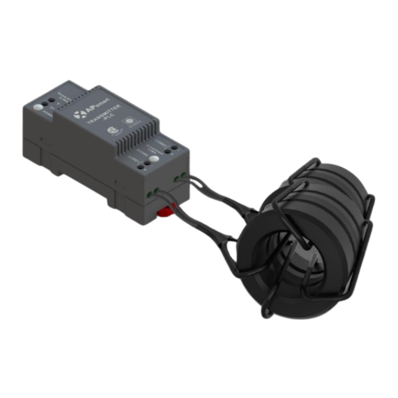
TRANSMITTER PRODUCTS Transmitter-PLC · Meets NEC 2017&2020 (690.12) requirements · Switching off Transmitter-PLC results in rapid shutdown of the output of PV modules · Meets SunSpec requirements · Equipped with single/dual core · Optional 85-264VAC power supply · Optional 180-550VAC power supply Transmitter-PLC-Outdoor Kit ·... -
Page 6: System Wiring Diagram
APsmart RSD-S-PLC, a PV module rapid shutdown unit. While powered on, the Transmitter-PLC sends a signal to the RSD-S-PLC units to keep the PV modules connected and supplying energy. RSD-S-PLC units automatically enter rapid shutdown mode when the Transmitter-PLC is switched off and resume energy production when power is restored to the Transmitter-PLC. - Page 7 SYSTEM WIRING DIAGRAM *PV1+ *PV2+ *Homerun only PV+ cable through core ① RSD-S-PLC ② Transmitter-PLC-Outdoor Kit ③ Inverter *PV1+ *PV2+ *Homerun only PV+ cable through core *④optional ① RSD-S-PLC ② Transmitter-PLC-Outdoor Kit ③ Inverter ④ Emergency stop button box(optional): Press the emergency stop button, the transmitter AC power supply is disconnected, the RSD closes the output, and the system rapid shutdown.
-
Page 8: Rsd-S-Plc Installation
RSD-S-PLC INSTALLATION ① RSD-S-PLC ② Inverter* * Inverter in diagram includes an integrated SunSpec-certified Rapid Shutdown Transmitter. User Manual... - Page 9 ② Be aware that only qualified professionals should install and/or replace the RSD-S-PLC. ③ Before installing or using an RSD-S-PLC, please read all instructions and warnings in the technical documents and on the inverter system itself as well as on the PV array.
- Page 10 Buckle RSD-D onto the PV module frame. NOTE: Do not place the RSD-S-PLC (including DC connectors) where exposed to the sun, rain or snow, even gap between modules. Allow a minimum of 3/4’’(1.5cm.) between the roof and the bottom of the RSD-S-PLC to allow proper air flow.
- Page 11 RSD-S-PLC INSTALLATION Step 2: Connect the input connectors of the RSD-S-PLC to the junction box, the device output DC voltage is within the range of 0.6 to 1v. NOTE: Do not short-circuit the RSD-S-PLC output connectors, otherwise it will be damaged.
- Page 12 NOTE: When installing RSD-S cable, the bending radius of the cable near the casing must be greater than 50 mm. Step 3: Connect the output connectors of the RSD-S-PLC in series to the string, the string open-air DC voltage is within the range of (0.6 ~ 1v) X #RSD-S-PLCs. (This range may vary due to different on-site environment.)
-
Page 13: Transmitter-Plc Installation
PLC fails to work, the Signal LED will not be blinking. If the Power LED is also not lit, check the power supply first. NOTE: Install the RSD-S-PLC before powering the Transmitter-PLC. • Mount Transmitter-PLC and power supply on DIN rail •... - Page 14 TRANSMITTER-PLC INSTALLATION NOTE: Install the RSD-S-PLC before powering the Transmitter-PLC. NOTE: The waterproof jacket and related accessories are not configured before delivery and customers need to buy by themselves. • Pass either positive or negative cables through cores (either both positive cables or both negative cables. Do not use one positive and one negative cable.) •...
- Page 15 TRANSMITTER-PLC INSTALLATION Drilling Guide for .75" Conduit Drilling Guide for 1" Conduit Note: The Outdoor Kit was not punched before delivery and customer need to make it themselves according to the actual situation. The figure is only for reference. User Manual...
-
Page 16: Technical Data-Rsd-S-Plc
TECHNICAL DATA—RSD-S-PLC Model RSD-S-PLC Input Data (DC) Input Operating Voltage Range 8-80V Maximum Cont. Input Current (Imax) Maximum Short Circuit Current(Isc) Output Data (DC) Output Operating Voltage Range 8-80V Maximum System Voltage 1000V/1500V Maximum Series Fuse Rating Mechanical Data Operating Ambient Temperature Range F to +185 F (-40 °C to + 85 °C) -
Page 17: Technical Data-Transmitter-Plc
TECHNICAL DATA—TRANSMITTER-PLC Mode Transmitter-PLC Main electrical data Input Voltage 12VDC Input Current 0.8A Communication Power Supply Residential(optional) 85-264VAC Input, 12VDC Output, 90 mm x 17.5 mm x 58.4 mm Commercial(optional) 180-550VAC Input, 12VDC Output, 125.2 mm x 32 mm x 102 mm Core data 25mm Core 11mm Core... -
Page 18: Technical Data-Transmitter-Plc-Outdoor Kit
TECHNICAL DATA—TRANSMITTER-PLC-OUTDOOR KIT Model Transmitter-PLC-Outdoor Kit Main electrical data Main electrical data Input Voltage 12VDC Input Current 0.8A Communication Power Supply Residential(optional) 85-264VAC Input, 12VDC Output, 90 mm x 17.5 mm x 58.4 mm Commercial(optional) 180-550VAC Input, 12VDC Output, 125.2 mm x 32 mm x 102 mm Core data 29mm Core Max.Current... -
Page 19: Ordering Information
Dual Core Transmitter-PLC-Outdoor Kit, 180-550VAC Power Supply, Emergency button 408012 Single Core Transmitter-PLC-Outdoor Kit, 85-264VAC Power Supply, Emergency button 408013 Dual Core Transmitter-PLC-Outdoor Kit, 85-264VAC Power Supply, Emergency button RSD-S-PLC 415002 1500V UL, 1.2m cable, Stäubli MC4 PV-KBT4&KST4 415001 1000V UL, 1.2m cable, Customized connector 8627 N Mopac Expy, Suite 150, Austin, TX 78759 | +1-737-218-8486 | +1-866-374-8538 | support@APsmartGlobal.com | APsmartGlobal.com...
Need help?
Do you have a question about the RSD-S-PLC and is the answer not in the manual?
Questions and answers