APsmart RSD-S-PLC Quick Installation Manual
Hide thumbs
Also See for RSD-S-PLC:
- Installation & user manual (19 pages) ,
- Installation and user manual (19 pages) ,
- Quick installation manual (2 pages)
Advertisement
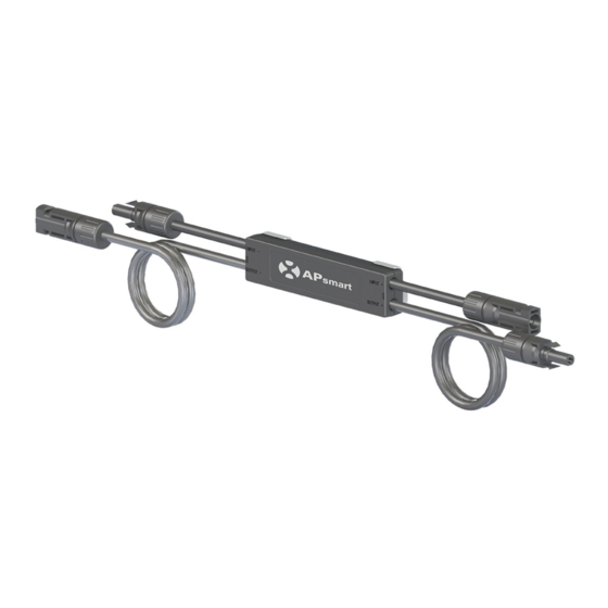
RSD-S-PLC Quick Installation Guide
INPUT-
OUTPUT-
Step1. Buckle RSD-S-PLC onto the PV module frame.
A.Back buckle
B.Front buckle
Step 2. Connect the input connectors of the RSD-S-PLC to the junction box, the device
output DC voltage is within the range of 0.6 to 1v.
NOTE: Do not short-circuit the RSD-S-PLC output connectors, otherwise it will be damaged.
NOTE: When installing RSD-D cable, the bending radius of the cable near the casing must be greater than 50 mm.
smart
INPUT+
OUTPUT+
Mounting brackets
1
2021/08/06 Rev2.6 | Quick Installation Guide
Advertisement
Table of Contents

Related Manuals for APsmart RSD-S-PLC


Summary of Contents for APsmart RSD-S-PLC
- Page 1 A.Back buckle B.Front buckle Step 2. Connect the input connectors of the RSD-S-PLC to the junction box, the device output DC voltage is within the range of 0.6 to 1v. NOTE: Do not short-circuit the RSD-S-PLC output connectors, otherwise it will be damaged.
- Page 2 √ × Step 3. CConnect the output connectors of the RSD-S-PLC in series to the string, the string open-air DC voltage is within the range of (0.6 ~ 1v) X #RSD-S-PLCs. (This range may vary due to different on-site environment.) NOTE: Do not connect homerun to inverter before finishing all strings connections and tests.
Need help?
Do you have a question about the RSD-S-PLC and is the answer not in the manual?
Questions and answers