APsmart RSD-S-PLC Installation & User Manual
Apsmart rapid shutdown system
Hide thumbs
Also See for RSD-S-PLC:
- Installation & user manual (19 pages) ,
- Installation and user manual (19 pages) ,
- Quick installation manual (2 pages)

Subscribe to Our Youtube Channel
Related Manuals for APsmart RSD-S-PLC


Summary of Contents for APsmart RSD-S-PLC
- Page 1 Installation / User Manual APsmart rapid shutdown system Rev2.0 2020/11/26 RSD-S-PLC TRANSMITTER-PLC TRANSMITTER-PLC OUTDOOR KIT © All Rights Reserved...
-
Page 2: Table Of Contents
TABLE OF CONTENTS IMPORTANT SAFETY INSTRUCTIONS---------------------------------------------------------1 RSD PRODUCTS----------------------------------------------------------------------------------2 TRANSMITTER PRODUCTS---------------------------------------------------------------------3 SYSTEM WIRING DIAGRAM--------------------------------------------------------------------4 RSD-S-PLC INSTALLATION---------------------------------------------------------------------6 TRANSMITTER-PLC INSTALLATION ----------------------------------------------------------9 TECHNICAL DATA—RSD-S-PLC---------------------------------------------------------------12 TECHNICAL DATA—TRANSMITTER-PLC-----------------------------------------------------13 TECHNICAL DATA—TRANSMITTER-PLC-OUTDOOR KIT----------------------------------14 ORDERING INFORMATION --------------------------------------------------------------------15... -
Page 3: Important Safety Instructions
· Before installing or using the RSD-S-PLC, please read all instructions and cautionary markings in the technical documents. · Be aware that the body of the running RSD-S-PLC is the heat sink and can reach high temperatures. To reduce risk of burns, do not touch the body of the RSD-S-PLC. -
Page 4: Rsd Products
· Meets SunSpec requirements RSD-S-PLC meets SunSpec requirements,maintaining normal function by continually receiving a heart-beat signal from the APsmart Transmitter-PLC. The RSD executes rapid system shutdown when Transmitter-PLC signal is absent. Users can manually execute rapid shutdown using Transmitter-PLC breaker switch. -
Page 5: Transmitter Products
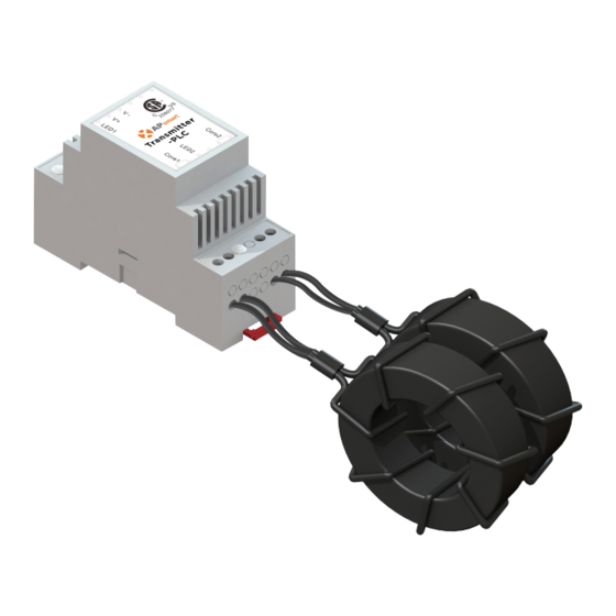
TRANSMITTER PRODUCTS Transmitter-PLC · Meets NEC 2017&2020 (690.12) requirements · Switch o Transmitter-PLC, rapid shutdown the output of PV modules · Meets SunSpec requirements · Equipped with single/dual core · Optional 85-264VAC power supply · Optional 180-550VAC power supply Transmitter-PLC-Outdoor Kit ·... -
Page 6: System Wiring Diagram
The APsmart Rapid Shutdown System Transmitter-PLC is part of a rapid shutdown solution when paired with APsmart RSD-S-PLC, a PV module rapid shutdown unit. While powered on, the Transmitter-PLC sends a signal to the RSD-S-PLC units to keep their PV modules connected and supplying energy. - Page 7 … *PV1+ *PV2+ … *Only (+) or (-) through core ① RSD-S-PLC ② Transmitter-PLC-Outdoor Kit ③ Inverter PV1+ PV1- PV2+ PV2- ① RSD-S-PLC ② Inverter * The inverter integrates a SunSpec certified Rapid ShutdownTransmitter.
-
Page 8: Rsd-S-Plc Installation
② Be aware that only qualified professionals should install and/or replace the RSD-S-PLC. ③ Before installing or using an RSD-S-PLC, please read all instructions and warnings in the technical documents and on the inverter system itself as well as on the PV array. - Page 9 Step 1: Install the RSD-S-PLC. DC input - DC input + DC output - DC output + Mounting brackets A. Back buckle B. Front buckle Note: Both installations can be installed anywhere on the PV module frame.
- Page 10 Step 2: According to the PV module arrangement, connect the output port of the RSD-S-PLC and connect the input port to the junction box. Input- Input + Input- Input + Output- Output + Output- Output + Step 3: Connect the output ports of two adjacent RSD-S-PLCs in series and then connect to the inverter with a self-made exten- sion cable.
-
Page 11: Transmitter-Plc Installation
Signal LED will not be blinking. If the Power LED is also not lit, check the power supply first. te: Install RSD-S-PLC before powering on Transmitter-PLC. • Mount Transmitter-PLC and power supply on DIN rail •... - Page 12 Note: 180/550Vac power supply isolation class I requires grounding. 85/264Vac power supply isolation class II does not require grounding. Note: Install RSD-S-PLC before powering on Transmitter-PLC. Max number Of Strings Per Core : DC cable Diameter Φ5.9mm Φ6.35mm Φ7mm...
- Page 13 Drilling Guide for .75" Conduit Single Core Dual Core 2x∅28 3x∅28 2x∅28 ∅28 Drilling Guide for 1" Conduit Single Core Dual Core...
-
Page 14: Technical Data-Rsd-S-Plc
Model RSD-S-PLC Input Data (DC) Input Operating Voltage Range 8-80V Maximum Cont. Input Current (Imax) Output Data (DC) Output Operating Voltage Range 8-80V Maximum S em oltage 1000V/1500V Mechanical Data Operating Ambient Temperatu r e Range -40 °F to + 185°F(-40°C to + 85°C) Dimensions (without cable &... -
Page 15: Technical Data-Transmitter-Plc
TECHNICAL DATA—TRANSMITTER-PLC Model Transmitter-PLC Main Electrical Data Input Voltage 12VDC Input Current 0.8A Communication P LC Power Supply Residential(optional) 85-264 VAC Input, 12VDC Output, 90 mm x 17.5 mm x 58.4 mm 180-550 VAC Input, 12VDC Output, Commercial(optional) 125.2 mm x 32 mm x 102 mm Core Data 29mm Core 11mm Core... -
Page 16: Technical Data-Transmitter-Plc-Outdoor Kit
TECHNICAL DATA—TRANSMITTER-PLC OUTDOOR KIT Model Transmitter-PLC Outdoor Kit Main Electrical Data Input Voltage 12VDC Input Current 0.8A Communication Power Supply Residential(optional) 85-264 VAC Input, 12VDC Output, 90 mm x 17.5 mm x 58.4 mm Commercial(optional) 180-550VAC Input, 12VDC Output, 125.2 mm x 32 mm x 102 mm Core Data Max. -
Page 17: Ordering Information
Dual Core Transmitter-PLC Outdoor Kit, 180-550VAC Power Supply 408006 Single Core Transmitter-PLC Outdoor Kit, 85-264VAC Power Supply 408007 Dual Core Transmitter-PLC Outdoor Kit, 85-264VAC Power Supply RSD-S-PLC 405002 1500V UL/1000V TUV, 1.2m cable, MC4 405001 1000V UL/TUV, 1.2m cable, Customized connector...
Need help?
Do you have a question about the RSD-S-PLC and is the answer not in the manual?
Questions and answers