APsmart RSD-D Quick Installation Manual
Hide thumbs
Also See for RSD-D:
- Installation & user manual (21 pages) ,
- Quick installation manual (2 pages) ,
- Installation & user manual (16 pages)
Advertisement
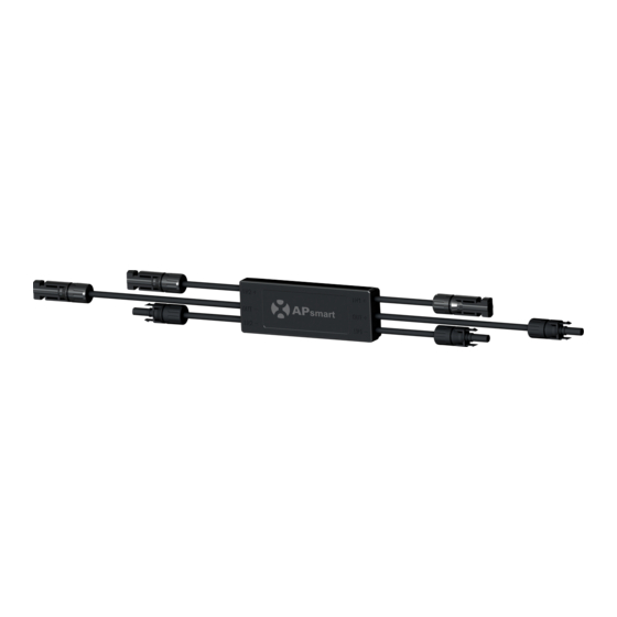
RSD-D Quick Installation Guide
INPUT2+
OUTPUT-
INPUT2-
Step1. Buckle RSD-D onto the PV module frame.
A.Back buckle
B.Front buckle
NOTE: Do not place the RSD-D (including DC connectors) where exposed to the sun, rain or snow, even gap
between modules. Allow a minimum of 3/4''(1.5cm.) between the roof and the bottom of the RSD-D to
allow proper air flow.
Step 2. Connect the INPUT1 connectors of the RSD-D to the first PV module junction box
and connect the INPUT2 connectors to second PV module, the device DC output voltage
is within the range of 1.2 ~ 2v.
NOTE: Do not short-circuit the RSD-D output connectors, otherwise it will be damaged.
smart
INPUT1+
INPUT1-
OUTPUT+
Mounting brackets
1
2022/05/27 Rev2.8 | Quick Installation Guide
Advertisement
Table of Contents

Subscribe to Our Youtube Channel
Related Manuals for APsmart RSD-D


Summary of Contents for APsmart RSD-D
- Page 1 A.Back buckle B.Front buckle NOTE: Do not place the RSD-D (including DC connectors) where exposed to the sun, rain or snow, even gap between modules. Allow a minimum of 3/4’’(1.5cm.) between the roof and the bottom of the RSD-D to allow proper air flow.
- Page 2 NOTE: When installing RSD-D cable, the bending radius of the cable near the casing must be greater than 50 mm. Bending Radius of the cable >50mm √ × √ × Step 3. Connect the output connectors of RSD-D in series to the string, the string open-air DC voltage is within the range of (1.2 ~ 2v) X #RSD-Ds.
Need help?
Do you have a question about the RSD-D and is the answer not in the manual?
Questions and answers