APsmart RSD-S-PLC Installation And User Manual
Rapid shutdown device & transmitter
Hide thumbs
Also See for RSD-S-PLC:
- Installation & user manual (19 pages) ,
- Installation and user manual (19 pages) ,
- Quick installation manual (2 pages)
Table of Contents
Advertisement
Quick Links
Advertisement
Table of Contents

Subscribe to Our Youtube Channel
Related Manuals for APsmart RSD-S-PLC


Summary of Contents for APsmart RSD-S-PLC
- Page 1 Installation /User Manual APsmart Rapid Shutdown Device & Transmitter Rev2.0 2020/11/26 RSD-S-PLC TRANSMITTER-PLC TRANSMITTER-PLC OUTDOOR KIT © All Rights Reserved 19925 Stevens Creek Blvd, Suite 100, Cupertino, CA 95014 +1 737-218-8486 | info@APsmartGlobal.com | APsmartGlobal.com...
-
Page 2: Table Of Contents
TABLE OF CONTENTS IMPORTANT SAFETY INSTRUCTIONS----------------------------------------------------------------------1 RSD PRODUCTS-----------------------------------------------------------------------------------------------2 TRANSMITTER PRODUCTS----------------------------------------------------------------------------------3 SYSTEM WIRING DIAGRAM---------------------------------------------------------------------------------4 RSD-S-PLC INSTALLATION----------------------------------------------------------------------------------6 TRANSMITTER-PLC INSTALLATION -----------------------------------------------------------------------9 TECHNICAL DATA—RSD-S-PLC----------------------------------------------------------------------------12 TECHNICAL DATA—TRANSMITTER-PLC-----------------------------------------------------------------13 TECHNICAL DATA—TRANSMITTER-PLC-OUTDOOR KIT----------------------------------------------14... -
Page 3: Important Safety Instructions
· Before installing or using the RSD-S-PLC, please read all instructions and cautionary markings in the technical documents. · Be aware that the body of the operating RSD-S-PLC is a heat sink and can reach high temperature. To reduce risk of burns, do not touch the body of the RSD-S-PLC. -
Page 4: Rsd Products
· Meets SunSpec requirements The RSD-S-PLC meets SunSpec requirements, maintaining normal function by continually receiving a heartbeat signal from the APsmart Transmitter. The RSD-S-PLC executes rapid system shutdown when the Transmitter signal is absent. Users can manually execute rapid shutdown using the Transmitter breaker switch. -
Page 5: Transmitter Products
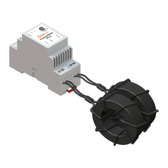
TRANSMITTER PRODUCTS Transmitter-PLC · Meets NEC 2017&2020 (690.12) requirements · Switching off Transmitter-PLC results in rapid shutdown of the output of PV modules · Meets SunSpec requirements · Equipped with single/dual core · Optional 85-264VAC power supply · Optional 180-550VAC power supply Transmitter-PLC-Outdoor Kit ·... -
Page 6: System Wiring Diagram
APsmart RSD-S-PLC, a PV module rapid shutdown unit. While powered on, the Transmitter-PLC sends a signal to the RSD-S-PLC units to keep the PV modules connected and supplying energy. RSD-S-PLC units automatically enter rapid shutdown mode when the Transmitter-PLC is switched off and resume energy production when power is restored to the Transmitter-PLC. - Page 7 ① RSD-S-PLC ② Transmitter-PLC-Outdoor Kit ③ Inverter ① RSD-S-PLC ② Inverter* * Inverter in diagram includes an integrated SunSpec-certified Rapid Shutdown Transmitter. User Manual...
-
Page 8: Rsd-S-Plc Installation
② Be aware that only qualified professionals should install and/or replace the RSD-S-PLC. ③ Before installing or using an RSD-S-PLC, please read all instructions and warnings in the technical documents and on the inverter system itself as well as on the PV array. - Page 9 Step 1: Install the RSD-S-PLC. DC input - DC input + DC output - DC output + Mounting brackets A. Back buckle B. Front buckle Note: Both installation methods can be used anywhere on the PV module frame. User Manual...
- Page 10 Step 2: According to the PV module arrangement, connect the output port of the RSD-S-PLC and connect the input port to the junction box. Step 3: Connect the output ports of two adjacent RSD-S-PLCs in series and then connect to the inverter with a self-made DC extension cable.
-
Page 11: Transmitter-Plc Installation
PLC fails to work, the Signal LED will not be blinking. If the Power LED is also not lit, check the power supply first. Note: Install the RSD-S-PLC before powering the Transmitter-PLC. • Mount Transmitter-PLC and power supply on DIN rail •... - Page 12 Note: Install the RSD-S-PLC before powering the Transmitter-PLC. • Pass either positive or negative cables through cores (either both positive cables or both negative cables. Do not use one positive and one negative cable.) • Connect wires to AC side of power supply...
- Page 13 Drilling Guide for .75" Conduit Drilling Guide for 1" Conduit User Manual...
-
Page 14: Technical Data-Rsd-S-Plc
TECHNICAL DATA—RSD-S-PLC Model RSD-S-PLC Input Data (DC) Input Operating Voltage Range 8-80V Maximum Cont. Input Current (Imax) Output Data (DC) Output Operating Voltage Range 8-80V Maximum System Voltage 1000V/1500V Mechanical Data Operating Ambient Temperature Range F to +185 F (-40 °C to + 85 °C) Dimensions (without cable&connectors) -
Page 15: Technical Data-Transmitter-Plc
TECHNICAL DATA—TRANSMITTER-PLC Model Transmitter-PLC Main electrical data Main electrical data Input Voltage 12VDC Input Current 0.8A Communication Power Supply Residential(optional) 85-264VAC Input, 12VDC Output, 90 mm x 17.5 mm x 58.4 mm Commercial(optional) 180-550VAC Input, 12VDC Output, 125.2 mm x 32 mm x 102 mm Core data 29mm Core 11mm Core... -
Page 16: Technical Data-Transmitter-Plc-Outdoor Kit
TECHNICAL DATA—TRANSMITTER-PLC-OUTDOOR KIT Model Transmitter-PLC-Outdoor Kit Main electrical data Main electrical data Input Voltage 12VDC Input Current 0.8A Communication Power Supply Residential(optional) 85-264VAC Input, 12VDC Output, 90 mm x 17.5 mm x 58.4 mm Commercial(optional) 180-550VAC Input, 12VDC Output, 125.2 mm x 32 mm x 102 mm Core data 29mm Core Max.Current...
Need help?
Do you have a question about the RSD-S-PLC and is the answer not in the manual?
Questions and answers