
Subscribe to Our Youtube Channel
Related Manuals for FlowLine EchoBeam LR80 Series


Summary of Contents for FlowLine EchoBeam LR80 Series
- Page 1 EchoBeam ® 80 GHz Radar Liquid & Solid Level Transmitter LR80, LR81, LR83 & LR85 Series Manual Flowline, Inc. | 10500 Humbolt Street, Los Alamitos, CA 90720 p 562.598.3015 f 562.431.8507 w flowline.com MN310255 Rev 10...
-
Page 2: Table Of Contents
Introduction Section One TABLE OF CONTENTS Section One | Introduction: ..................2 Table of Contents: ....................2 Sensor Models: ....................6 Operating Principle: .................... 7 Features: ......................7 Benefits: ......................7 Limitations: ......................7 Specifications: ..................... 8 Dimensions: ...................... 12 Safety Precautions: ................... - Page 3 Introduction Section One TABLE OF CONTENTS (CONTINUED) Section Six | Configuration Using LevelTap™ App: ..........43 Using the LevelTap™ Bluetooth App: ..............43 Connecting EchoBeam ® to LevelTap™: ............. 43 Bluetooth Connections: ..................44 Using LevelTap™ App: ..................44 Measure the Tank (Basic Dimensions): .............. 45 Confirm the Measurements: ................
- Page 4 Introduction Section One TABLE OF CONTENTS (CONTINUED) Section Eleven | Diagnostics: ..................73 EchoCurve Diagnostics: ..................73 What is a Good EchoCurve?: ................74 What is a Bad EchoCurve?: ................74 False EchoCurve: ....................76 Simulation: ......................77 Sensor Status: ....................77 Section Twelve | Data Sampling: ................
- Page 5 Navigation: ......................87 Sensors: ....................88 Configurations: ..................88 Documentation: ..................89 Technical Support:.................. 90 About LevelTap: ..................91 About Flowline: ..................91 Account: ....................92 General: ....................93 Privacy: ....................93 Security: ....................93 Notifications: ................... 94 Help: ....................... 94 Logout: ....................
-
Page 6: Sensor Models
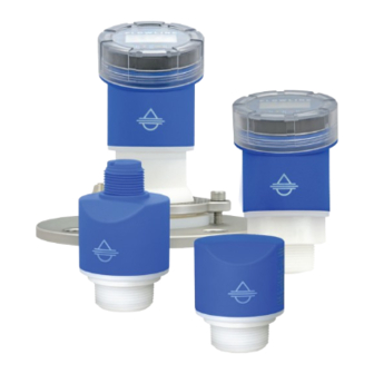
Introduction Section One SENSOR MODELS Offered in four different models, EchoBeam is an FMCW radar level sensor that provides a continuous output ® proportional to the liquid level in a tank or sump. Available outputs include 4-20mA, 4-20mA w/ HART, ModBus RTU and SDI-12. -
Page 7: Operating Principle
Section One OPERATING PRINCIPLE Flowline’s EchoBeam is frequency modulated continuous wave (FMCW) radar that operates at 80 GHz normally. The antenna transmits high frequency as well as the frequency modulated radar signal. The frequency of the radar signal linearly increases. The transmitter radar signal is reflected by the dielectric of the liquid and/or solid to be measured and received by antenna. -
Page 8: Specifications
Introduction Section One SPECIFICATIONS Measurement range: LR80 Max. range liquids: 32.81 feet (10m) with media dielectric ≥1.6 and no agitation* LR80 Max. range solids: 16.40 feet (5m) with media dielectric ≥ 6 and no dust LR81 Max. range liquids: 98.42 feet (30m) with media dielectric ≥10 and no agitation* LR81 Max. - Page 9 Introduction Section One Max. consumption: 4-20mA (HART): 22.5 mA Modbus & SDI-12: 1.5 watt Process temperature: LR80: F: -40° to 140° C: -40° to 60° LR81: F: -40° to 176° C: -40° to 80° LR83: F: -40° to 212° C: -40° to 100° LR85: F: -40°...
- Page 10 Introduction Section One Mounting Gasket: Viton GLT (required with 1½” G and M80 x 3 versions only) Air purge conn.: ¼” tube compression fitting (LR85 series only) Mount gasket: Viton GLT (fluoroelastomer), 1½” G version only Classification: General Purpose, Approvals: General purpose: cCSAus (UL 61010-1:2012 &...
- Page 11 Introduction Section One ACCURACY TABLES MN310255 Rev 10...
-
Page 12: Dimensions
Introduction Section One DIMENSIONS LR80 Series – Vertical Orientation MN310255 Rev 10... - Page 13 Introduction Section One DIMENSIONS LR81 Series – Vertical Orientation LR81 Series – Horizontal Orientation MN310255 Rev 10...
- Page 14 Introduction Section One DIMENSIONS LR83 Series MN310255 Rev 10...
- Page 15 Introduction Section One DIMENSIONS LR85 Series (Flange Mount) MN310255 Rev 10...
- Page 16 Introduction Section One DIMENSIONS LR85 Series (3” NPT Thread Mount) MN310255 Rev 10...
-
Page 17: Safety Precautions
PRODUCT. This manual includes information on the EchoBeam ® Radar Level Transmitter from FLOWLINE. Please refer to the part number located on the sensor label to verify the exact model which you have purchased. User’s Responsibility for Safety: Flowline manufactures a broad range of level sensing technologies. -
Page 18: Section Two | Getting Started
Prior to purchasing the sensor, you may have to submit a Level Application Questionnaire (flowline.com/LAQ). Based upon the information provided, it resulted in a suggested part number. Therefore, confirm that the suggested part number matches the part number of the purchased sensor. If any of the above does not match and/or meet your application requirements, please contact your distributor. -
Page 19: Using The Leveltap™ App
Getting Started Section Two CONFIGURATION METHODS The main method for configuring the EchoBeam® is to use the LevelTap™ App on a Smartphone. This can be used to configure and communicate with the EchoBeam® transmitter. The Bluetooth signal has a maximum range of 26’... -
Page 20: Connecting An Echobeam ® Transmitter To Leveltap™ App
Getting Started Section Two CONNECTING ECHOBEAM ® TO LEVELTAP™ When accessing LevelTap™, you will initially see a list of sensors that are connected or paired, as well as any unpaired sensors. Prior to your first sensor configuration, the screen will only show powered sensors that are unpaired. - Page 21 Getting Started Section Two LEVELTAP™ SENSOR INFORMATION LevelTap™ provides key information about each sensor. Sensor’s Menu • 14.001 m – This is the value the sensor is displaying. • LEVEL HEIGHT / LIQUID – This is what the display is showing (either Level Height, Distance, Current or Percentage) as well as confirming the media is either a liquid or a solid.
-
Page 22: Basic Requirements
Getting Started Section Two BASIC REQUIREMENTS When the antenna transmits the frequency-modulated continuous wave, it has a certain transmission angle or Beam Angle. Series LR80 LR81 LR83 LR85 Beam Angle 8° 8° 6° 4° Min. Distance 7.9” 7.9” 7.9” 19.7” from Side Wall (200mm) (200mm) -
Page 23: Part Number
Section Two PART NUMBER Prior to purchasing the sensor, you may have submitted a Level Application Questionnaire (flowline.com/LAQ). Based upon the information provided it resulted in a suggested part number. Where so, confirm the suggested part number matches the part number of the sensor. The part number can be found on the outside label on the... -
Page 24: Section Three | Measure The Tank
Measure the Tank Section Three BASIC DIMENSIONS Properly locating the sensor and correctly measuring the tank, sets the foundation for sensor configuration. In doing so, consider the sensor’s mounting location with respect to relevant fittings, risers, dome tops or cone bottoms, and identify where the measurements are taken from the sensor. -
Page 25: Cone Bottom Tanks
Measure the Tank Section Three CONE BOTTOM TANKS When installing EchoBeam® on a tank with a cone shaped bottom, the sensor’s mounting location and tank geometry may influence the sensor’s configuration setting. If your requirement is to measure into the cone, location of the sensor is critical. -
Page 26: Top Of Tank Considerations
Measure the Tank Section Three TOP OF TANK CONSIDERATIONS When installing EchoBeam® on an enclosed tank top, the installed position of the sensor’s antenna or measurement location, above or below the top, must be taken into consideration when determining your sensor configuration settings. -
Page 27: Section Four | Install The Transmitter
Consider any effects from the application temperature, pressure or media. RADIO COMPLIANCE See the radio addendum supplementary instructions for radar level measuring instruments with radio approvals at www.flowline.com regarding the safe and regulatory compliant use of this device. MN310255 Rev 10... -
Page 28: Mounting Position
Install the Transmitter Section Four MOUNTING POSITION Mount the Sensor Perpendicular to the Liquid Level Always mount the sensor perpendicular to the surface of the liquid. This will enable the return echoes to reach the sensor. Mounting the sensor off-axis will result in weaker return echoes or no return echoes, depending on the degree of angle. - Page 29 Install the Transmitter Section Four SIDE WALL The minimum distance (independent of beam angle) that the transmitter can be mounted next to the straight side wall of the tank is 7.9” (200mm) for the LR80, LR81 and LR83 series and 19.7” (500mm) for the LR85 series as measured from the transmitter centerline to the side wall.
- Page 30 Install the Transmitter Section Four CONE BOTTOM TANKS (LIQUIDS) In cone bottom tanks, it can be advantageous to mount the sensor in the center of the tank, making it possible for the sensor to measure closer to the bottom of the tank. If the sensor is mounted over an angled bottom, and the level drops below the angle, the echo will be deflected away from the sensor, resulting in poor operation.
- Page 31 Install the Transmitter Section Four FLANGE RISER INSTALLATION The transmitter can be installed within a riser if the material (liquids or solids) has a strong reflective property (dielectric constant) providing a strong echo return. When installing the transmitter on a flange with a riser (or any fitting that is tall and narrow), make sure the ends of the riser are smooth and without bulges or burrs.
-
Page 32: Beam Angle
Install the Transmitter Section Four BEAM ANGLE The emitted frequency-modulated continuous wave signal will expand along its specified beam angle for the entire height of the tank. Place the transmitter so that objects will not interfere with the beam path underneath the sensor. -
Page 33: Bypass Installation
Install the Transmitter Section Four BYPASS INSTALLATION Bypass installations can avoid issues from turbulence, substantial foam or other equipment in the sensors beam path. Note: The use of a bypass is not recommended with liquids that significantly coat or scale. As a rule, if the inside wall of the tank has material build-up, then the inside of the bypass will also have build-up that will affect the transmitter’s operation. -
Page 34: Standpipe Installation
Install the Transmitter Section Four STANDPIPE INSTALLATION An alternative to a metal bypass is to install the transmitter on a metal standpipe mounted inside of the tank. To avoid issues from turbulence, substantial foam or other equipment in the sensors beam path such as mixers, install the sensor within a standpipe (still well). -
Page 35: Weir Installation
Install the Transmitter Section Four WEIR INSTALLATION When installing EchoBeam in a Weir application, always defer to the installation requirements from the Weir ® manufacturer. Below are some typical installation requirements. • Mount the transmitter upstream from the weir. Always install it in the center of the weir. •... -
Page 36: Flume Installation
Install the Transmitter Section Four FLUME INSTALLATION When installing EchoBeam in a Flume application, always defer to the installation requirements from the ® Flume manufacturer. Below are some typical installation requirements. • Always install it in the center of the flume. Keep the transmitter no less than 15.75”... -
Page 37: Section Five | Wire The Transmitter
Wire the Transmitter Section Five SUPPLY VOLTAGE Always check the part number to determine the output and supply voltage of your transmitter. 4-20MA LOOP POWERED OUTPUT Transmitter power supply and current signal share the same two-wire shielded cable. The sensor supply voltage should never exceed 30 VDC and be greater than 12 VDC. -
Page 38: Wiring To Displays, Controllers & Plcs (General Purpose)
Wire the Transmitter Section Five WIRING TO DISPLAYS, CONTROLLERS & PLC’S (GENERAL PURPOSE) Below are examples of how to wire EchoBeam to common displays, controllers and PLC’s. ® DataView™ LI55 Series Level Controller DataLoop™ LI23 Series DataLoop™ LI23 Series Level Indicator Level Indicator (Without Backlight) (With Backlight) - Page 39 Wire the Transmitter Section Five WIRING TO DISPLAYS, CONTROLLERS & PLC’S (GENERAL PURPOSE) DataPoint™ LC52 Series DataPoint™ LC52 Series Level Controller Level Controller (*JWA Mode - Factory Setting) (*JWB Mode) *See LC52 manual for jumper settings *See LC52 manual for jumper settings Generic Loop Generic PLC Powered Display...
-
Page 40: Hart Loop Powered Output
Wire the Transmitter Section Five 4-20MA / HART LOOP POWERED OUTPUT The advantage of a HART protocol is that it can communicate over existing 4–20 mA analog current loops. HART shares the two wires used by the 4-20mA signal wires. The transmitter’s supply voltage should never exceed 30 VDC and be greater than 12 VDC. -
Page 41: Modbus / Rs485 Output
Wire the Transmitter Section Five MODBUS/RS485 OUTPUT Transmitter power supply is provided with 2 wires and the RS485 communication is provided on two separate wires. A single 4-conductor shielded cable can be used or two separate 2-conductor cables can be used with the Modbus / RS485 output. -
Page 42: Sdi-12 Output
Wire the Transmitter Section Five SDI-12 OUTPUT Serial Digital Interface at 1200 Baud (SDI-12) is an asynchronous, serial data transmission protocol. It is often used as a communication platform between data loggers and transmitters in environmental applications. Transmitter power is supplied through Power / Red, and the Ground is through Ground / Black. The SDI-12 output is provided through Data / White. -
Page 43: Using The Leveltap™ Bluetooth App
Configuration Using LevelTap™ App Section Six USING THE LEVELTAP™ BLUETOOTH APP EchoBeam® is configured through LevelTap™ App, an application-based software program that uses Bluetooth to communicate with EchoBeam® via your smartphone or tablet. LevelTap™ is downloaded via the App Store for iOS and iPadOS operating systems, and Google Play or Baidu for the Android operating system. -
Page 44: Bluetooth Connections
Configuration Using LevelTap™ App Section Six BLUETOOTH CONNECTION A Smartphone with the LevelTap™ App as used to configure and communicate with the EchoBeam ® transmitter. The Bluetooth signal has a maximum range of 26 feet (8m) under ideal conditions (direct line of sight without obstructions). -
Page 45: Measure The Tank (Basic Dimensions)
Configuration Using LevelTap™ App Section Six MEASURE THE TANK (BASIC DIMENSIONS) EchoBeam measures the distance between the ® sensor and the liquid surface below. Measuring the tank is one of the most important aspects in configuring the transmitter. When measuring the tank, consider the location of the transmitter with respect to fittings, risers, dome tops and bottoms, and identify where the measurements are taken... -
Page 46: Step By Step Configuration
Configuration Using LevelTap™ App Section Six STEP BY STEP CONFIGURAITON Use this option for first time configurations. This method will walk you through all the information needed to configure your transmitter. Step 1 will ask for the following settings: Sensor Name •... -
Page 47: Step 3 - Set The Fill-Height (20Ma)
Configuration Using LevelTap™ App Section Six STEP BY STEP CONFIGURAITON (CONTINUED) Step 3 – Setting the Fill-Height (20mA): Input the distance from the bottom • of the tank to the maximum fill level which defines the 20mA set point. Step 4 - Setting the Display Value: Select the level height, air gap •... -
Page 48: Step 5 - Check The Echo Curve
Configuration Using LevelTap™ App Section Six CHECK THE ECHOCURVE This function graphically displays the primary echo return(s) the transmitter sees, the location and amplitude of the return(s), and the numeric air gap distance from the bottom of the transmitter to the level below. Note: This step should only be performed after having completed the prior four configuration steps and with the transmitter installed on the tank. -
Page 49: Section Seven | Quick Adjust
Quick Adjust Section Seven The Quick Adjust is ideal for making changes to the main level settings. It can also as a quick configuration method for experienced users of LevelTap™ App. To access Quick Adjust, Open Configuration and then select Quick Adjust. •... -
Page 50: Section Eight | Advanced Configuration
Advanced Configuration Section Eight PROCESS ADJUSTMENTS OVERVIEW These optional functions are intended to improve transmitter performance in applications with the below process and/or installation characteristics. The Advanced Configuration has 4 categories for enhancing the performance of EchoBeam . The categories ®... -
Page 51: Settings
Advanced Configuration Section Eight SETTINGS Settings have 4 categories (Range Adjust, HART, Level Variables and Signal Properties). RANGE ADJUST These settings are used to fine tune EchoBeam ® Dead Band (d) • o This setting defines the minimum distance that the EchoBeam will ®... - Page 52 Advanced Configuration Section Eight SETTINGS Settings have 4 categories (Range Adjust, HART, Level Variables and Signal Properties). RANGE ADJUST These settings are used to fine tune EchoBeam ® Maximum Range (d) • o This setting defines the maximum distance that the sensor will detect valid echo returns.
- Page 53 Note: This function should only be performed by a trained technician. Never change this setting unless instructed by a Flowline representative. Note: Record this setting if a Factory reset is performed. Write to Unit is used to save any changes to the sensor. Any changes made are not saved into EchoBeam ®...
-
Page 54: Hart
HART 7.0 certified and can be configured using a HART ® communicator. The Device Descriptor (DD) files have been released on the Flowline website and can be installed onto your communicator. The files can be found on the individual EchoBeam ®... -
Page 55: Level Variable
Advanced Configuration Section Eight SETTINGS Settings has 4 categories (Range Adjust, HART, Level Variables and Signal Properties) LEVEL VARIABLES Low Dielectric • o Used when measuring a medium with a low dielectric constant and the reflection from the bottom of the tank is stronger than the medium reflection. - Page 56 Advanced Configuration Section Eight SETTINGS Settings has 4 categories (Range Adjust, HART, Level Variables and Signal Properties) LEVEL VARIABLES Multiwave • o Used when there are multiple return echoes displayed in the EchoCurve. o Selections are YES or NO with NO as the default. Below is one valid echo that is above the envelop curve and is wide with the actual...
-
Page 57: Signal Properties
Advanced Configuration Section Eight SETTINGS Settings has 4 categories (Range Adjust, HART, Level Variables and Signal Properties) SIGNAL PROPERTIES First Echo • o Used when the sensor has difficulty seeing the first echo return. o This setting adjusts the peak strength (dB) of the first echo. o Default is Normal…settings are listed below: Normal - No adjustment ... - Page 58 Advanced Configuration Section Eight SETTINGS Settings has 4 categories (Range Adjust, HART, Level Variables and Signal Properties) SIGNAL PROPERTIES False Echo Memory • Performing a False Echo Memory will help the sensor filter out any false signals caused by obstructions (mixer blades, side wall weld joints, fill pipes, etc.) or abnormalities within the measurement range.
- Page 59 Advanced Configuration Section Eight SETTINGS Settings has 4 categories (Range Adjust, HART, Level Variables and Signal Properties) SIGNAL PROPERTIES Echo Threshold (dB) • o Echo Threshold and Envelope Level are both tied to the Envelope. o Echo Threshold is the difference the return signal must exceed above the Envelope so that the return signal can be considered a valid level (liquid or solids).
-
Page 60: Volumetric
Advanced Configuration Section Eight VOLUMETRIC When volume is selected, the 4-20 mA output from the sensor will be proportional to the volume of the tank, not the height of the tank. This means that the current output will track the volume of the tank (in gallons or liters). -
Page 61: Tank Properties
Advanced Configuration Section Eight TANK PROPERTIES Use this section to confirm the units of measurement and units of volume as well as entering the dimensions for the tank. Confirm Units of Measurement • o Options include in, ft, mm, cm or Confirm Units of Volume •... -
Page 62: Volumetric Adjustments & Output At Fill Height
Advanced Configuration Section Eight VOLUMETRIC ADJUSTMENTS & OUTPUT AT FILL HEIGHT Use this feature to adjust the volume output to match the size of your tank and to confirm the outputs for the configuraitons. VOLUMETRIC ADJUSTMENTS Calculated Max Volume: XXXXXX •... -
Page 63: Strapping Table
Advanced Configuration Section Eight VOLUMETRIC (STRAPPING TABLE) In the event the tank shape is not listed under Select Tank Shape, choose Strapping Table to manually enter a height vs. volume table for the tank. TANK PROPERTIES (STRAPPING TABLE) Confirm Units of Measurement •... -
Page 64: How Tank Shape Effects Tank Volume
Advanced Configuration Section Eight HOW TANK SHAPE EFFECTS VOLUME In the examples below, the sensors are also configured with SH = 64” and FH = 60”. The current output in a linear tank will act as expected with volume increase matching equal changes to level. However, the current output in the Non-Linear tank will reflect the actual changes in volume. -
Page 65: Flume Flow
Advanced Configuration Section Eight FLUME FLOW This setting is used to change the output of the transmitter from a linear signal proportional to the height of liquid in the tank into a non-linear signal that corresponds to the flow rate in a Flume. Select Flume Shape •... - Page 66 Advanced Configuration Section Eight FLUME PROPERTIES Use this section to confirm the units of flow, sensor height and flume size. Units of Flow • o Options include M^3/s, M^3/min, M^3/hour, M^3/day, Liter/min, Liter/hour, Liter/day, MLiter/Day, ft^3/Min, ft^3/hour, ft^3/day, Gal/min, Gal/hour, Gal/day, MGal.day, Gal_Imp/min, Gal_imp/hour and Gal_imp/day.
- Page 67 Advanced Configuration Section Eight FLUME FLOW VARIABLES Use this section to confirm the flow variables associated with the selected flume. Maximum Height (Max H) • o The is the maximum height of the flume. The height is predetermined from the selection of the length or angle of •...
-
Page 68: Weir Flow
Advanced Configuration Section Eight WEIR FLOW Configure the sensor to convert weir level height into flow rate and output in flow rate units. Select Weir Shape • o First step is to select the Weir Shape that best fits your application. o Options include V-Notch, Rectangular Contracted, Rectangular Suppressed and Cipolleti. - Page 69 Advanced Configuration Section Eight WEIR PROPERTIES Use this section to confirm the units of flow, sensor height and weir length/angle. Units of Flow • o Options include M^3/s, M^3/min, M^3/hour, M^3/day, Liter/min, Liter/hour, Liter/day, MLiter/Day, ft^3/Min, ft^3/hour, ft^3/day, Gal/min, Gal/hour, Gal/day, MGal.day, Gal_Imp/min, Gal_imp/hour and Gal_imp/day.
- Page 70 Advanced Configuration Section Eight WEIR FLOW VARIABLES Use this section to confirm the flow variables associated with the slected weir. Maximum Height (Max H) • o The is the maximum height of the weir. The height is predetermined from the selection of the length or angle of •...
-
Page 71: Section Nine | Configuration File
Configuration File Section Nine CONFIGURATION FILE Save, load or export a configuration. SAVE • Configuration Name o Input a name to identify the configuration. o This feature will save the configuration on the EchoBeam and will ® allow the configuration to be loaded onto other transmitters. o Configuration name is limited to 36 characters. -
Page 72: Section Ten | Configuration Photos
Configuration Photos Section Ten CONFIGURATION PHOTOS Use this feature to take a photo of the EchoBeam installed in the ® application. UPLOAD PHOTOS Click on the Camera Icon to take a Photo. • o You can either take a photo directly with your Smartphone camera or select from your photo library. -
Page 73: Section Eleven | Diagnostics
Diagnostics Section Eleven ECHOCURVE DIAGNOSTICS This function graphically displays the primary echo return(s) the sensor sees, the location and amplitude of the return(s), and the numeric air gap distance from the bottom of the transmitter to the level below. The distance vs. -
Page 74: What Is A Good Echocurve
Diagnostics Section Eleven WHAT IS A GOOD ECHOCURVE? EchoCurve presents a physical representation of the return signal across the operational range for the radar transmitter. There are two components to observe when looking at the EchoCurve: Check the Peak(s) along the EchoCurve •... - Page 75 Diagnostics Section Eleven WHAT IS A BAD ECHOCURVE? There are several elements to watch out for with a Bad EchoCurve. The number one solution for correcting a Bad EchoCurve will be the creation of a False EchoCurve. Multiple Peaks before or after the liquid or solids level •...
-
Page 76: False Echocurve
Diagnostics Section Eleven FALSE ECHOCURVE Performing a False EchoCurve will help the sensor filter out any false signals caused by obstructions (mixer blades, side wall weld joints, fill pipes, etc.) or abnormalities within the measurement range. This function maps all echo returns within the tank, differentiating between actual and false echoes. Echoes identified as false will be stored into the False EchoCurve and will not be considered in the level measurement of liquids or solids. -
Page 77: Simulation
Diagnostics Section Eleven SIMULATION Simulate various level conditions. • Simulation Simulate various level conditions by manually adjusting the output of EchoBeam ® . This can be used to confirm functionality of a system without having to wait for the level in the tank to rise or fall to a specific level (i.e., If you need a high alarm to activate at 9.5 feet you can use Simulate to output the equivalent current for 95% without having to raise the liquid or solids level to the actual 9.5 feet). -
Page 78: Section Twelve | Data Sampling
Data Sampling Section Twelve SETUP AND ENABLE Select data intervals and activate. Measured from the edge of the antenna, this function allows 1,000 points of air gap distance data and 10 EchoCurve data plots to be captured and stored in sensor memory. When the memory is full, new data will be saved and the oldest data will be erased. - Page 79 Data Sampling Section Twelve EchoCurve Interval • Set the time between EchoCurves. The minimum interval is 3 minutes, and the maximum is 24 hours. o Use scroll to set into Hour, Minute, Second format and click on Confirm to save interval. o The Data Window value (seen underneath the time interval field) will show the length of time the data covers.
-
Page 80: Distance Data
Data Sampling Section Twelve DISTANCE DATA View data plot of distance over time. Distance Data • o The Distance plot shows the last 1,000 points stored within the sensor’s log. If power has been lost at any time during this window, it will be indicated with a zero value. -
Page 81: Export Data
Data Sampling Section Twelve EXPORT DATA Email configuration and data files. Email Export Data • o Export and send a CSV file of data, 10 plot images, and a configuration summary text file via email. o Enter Email address of recipient of data. o Click Export to send the Email. -
Page 82: Section Thirteen | Security
Security Section Thirteen WRITE PROTECT Requires a PIN code to alter critical settings. Write Protect • o Enables the sensor to be protected with a 6-digit security code. o The code prevents the changing of parameters without entering the code prior to making any change. Note: This function should only be performed by a trained technician. -
Page 83: Factory Reset
Security Section Thirteen FACTORY RESET Reset sensor back to factory settings. Default Configurations • o Click on the Factory Reset button to return the EchoBeam ® back to its original factory settings. Series LR80 LR81 LR83 LR85 Sensor Name LR80 LR81 LR83 LR85... -
Page 84: Section Fourteen | Troubleshooting
Troubleshooting Section Fourteen TROUBLESHOOTING OVERVIEW Begin with the table below to help troubleshoot EchoBeam ® Problem Solution Move closer to the transmitter. Line of Sight with the transmitter works best. Cannot pair to transmitter Make sure no one else is currently paired to the transmitter. Only one device can be paired to the transmitter at a time. -
Page 85: Error Codes
Troubleshooting Section Fourteen ERROR CODES – 4-20MA/HART WITH DISPLAY Error Code Display Code Error Definition Display communication error. Typically appears when display module is CommErr not attached correctly. May also indicate communication error between the display and the main electronics. ROM write error. -
Page 86: Sdi-12
Troubleshooting Section Fourteen ERROR CODES – SDI-12 Error Code Display Code Error Definition StateOK Display communication error. Typically appears when display CommErr module is not attached correctly. May also indicate communication error between the display and the main electronics. ROM write error. EEPROM is no longer operational broken. -
Page 87: Section Fifteen
About Flowline • This feature provides a brief description of Flowline™. • Survey This feature links to a brief survey on Flowline™ and the LevelTap™ App. Account • This feature reviews the basic information provided to the LevelTap™ App. Notifications •... -
Page 88: Sensors
Appendix Section Fifteen SENSORS This returns to the Sensor’s Menu. CONFIGURATIONS This feature lists all saved configurations. Clicking on any saved configuration will show the key configuration settings for that configuration. MN310255 Rev 10... -
Page 89: Documentation
Appendix Section Fifteen DOCUMENTATION This feature provides links to technical documents that support EchoBeam . Access to the internet (via ® Cellular or Wi-Fi) is required. Web Page Data Sheet Quick Start Manual Wiring MN310255 Rev 10... -
Page 90: Technical Support
Appendix Section Fifteen TECHNICAL SUPPORT LevelTap™ support is available via phone during business hours or email anytime. MN310255 Rev 10... -
Page 91: About Leveltap
Appendix Section Fifteen ABOUT LEVEL TAP This feature provides a brief description of the LevelTap™ App as well as Release Notes and License Agreements. ABOUT FLOWLINE This feature provides a brief description of Flowline™. MN310255 Rev 10... -
Page 92: Account
Appendix Section Fifteen ACCOUNT This feature reviews the basic information provided to the LevelTap™ App. General • Language and Notifications. Privacy • Configuration file and location sharing. Security • Password, touch and Face ID verification. MN310255 Rev 10... -
Page 93: General
LevelTap. PRIVACY Location Sharing • Sharing your location will allow Flowline to better respond and communicate. Your location data will always be kept private and secure. SECURITY Update Password • Use a strong password using at least 8 characters, upper and lowercase letters, a number, and at least one special character. -
Page 94: Notifications
Appendix Section Fifteen NOTIFICATIONS This feature lists all configurations that have been sent to the LevelTap™ App. An orange dot will appear if the configuration has not been imported. HELP This feature list different options for getting help with the LevelTap™ App or with the level transmitter. Options include access to documentation, technical support, etc. -
Page 95: Logout
Appendix Section Fifteen LOG OUT This feature logs out the end user from the LevelTap™ App. When Log Out is selected, your session with LevelTap™ will have ended. MN310255 Rev 10... -
Page 96: Factory Settings
Appendix Section Fifteen FACTORY SETTINGS Below are the Sensor Height (4mA) and Fill-Height (20mA) factory settings for each sensor. Sensor Name: LR81 LR81 LR83 LR85 Application: Liquids Liquids Liquids Solids Units of Measurement: Fail-Safe Output: 20.5mA 20.5mA 20.5mA 20.5mA Sensor Height: 32.81 ft 98.42 ft 98.42 ft... -
Page 97: Lr80 Maximum Liquid Range Deration
Appendix Section Fifteen LR80 MAXIMUM RANGE DERATION FOR LIQUIDS The maximum range (under ideal conditions) for the LR80 series is 32.81’ (10m). There are several factors which will reduce the maximum range of the radar transmitter. The two key factors are the dielectric constant for the liquid being measured and the surface of the liquid. -
Page 98: Lr81 Maximum Liquid Range Deration
Appendix Section Fifteen LR81 MAXIMUM RANGE DERATION FOR LIQUIDS The maximum range (under ideal conditions) for the LR81 series is 98.42’ (30m). There are several factors which will reduce the maximum range of the radar transmitter. The two key factors are the dielectric constant for the liquid being measured and the surface of the liquid. -
Page 99: Modbus Output Definitions
Appendix Section Fifteen MODBUS RTU OUTPUT DEFINITIONS Communication Parameters: Hardware interface: RS485 Baud rate: 9600 Modbus RTU: 8, N, 1 Error Checking: CRC16 polynomial A001 Default Address: Modbus function codes supported: Function 03 - Read Register/s. Function 06 - Write Single Register Examples: Function 03 - Read Register/s. - Page 100 Appendix Section Fifteen Register Mapping: 0x0000 Distance measurement in centimeters (read only) 0x0001 Distance measurement in millimeters (read only) 0x0002 Level measurement in centimeters (read-only) 0x0003 Level measurement in millimeters (read-only) 0x0004 Measurement status (read-only); = Normal = Comm Err - Display not connected or broken = EEProm Err - write failure, EEPROM is broken = PLL Err - antennae circuit is broken = SYSBUSY - Slow response due to large data request or low supply voltage...
-
Page 101: Sdi-12 Output Definitions
Appendix Section Fifteen SDI-12 OUTPUT DEFINITIONS Serial Port Setting SDI 1200 baud rate 1 start, 7 data, 1 parity even, 1 stop. Supports SDI 1.4 Supported Commands Name Command Response Continuous spacing Break for at least 12 None milliseconds Acknowledge a<CR><LF>... - Page 102 Appendix Section Fifteen Supported Commands (continued) No. Name Response Command Start Concurrent Atttnn<CR><LF> Measurement aCC! and Request Additional Concurrent Atttnn<CR><LF> Measurement aCC1! … aCC9! and Request Continuous Measurements A<values><CRC><CR><LF> aRC0! … ARC9! and Request a<value><CR><LF> value +0, meter; +1 feet; +2 in; +3 cm; +4 Extended Read Unit aXRDU! Commands...
- Page 103 Appendix Section Fifteen This Page Left Intentionally Blank MN310255 Rev 10...
-
Page 104: Section Sixteen | Warranty, Returns And Limitations
PERSON IS AUTHORIZED TO MAKE ANY OTHER WARRANTIES OR REPRESENTATIONS ON BEHALF OF FLOWLINE. This warranty will be interpreted pursuant to the laws of the State of California. If any portion of this warranty is held to be invalid or unenforceable for any reason, such finding will not invalidate any other provision of this warranty.
Need help?
Do you have a question about the EchoBeam LR80 Series and is the answer not in the manual?
Questions and answers