Table of Contents
Advertisement
Quick Links
Advertisement
Table of Contents

Related Manuals for FlowLine EchoBeam LR83 Series


Summary of Contents for FlowLine EchoBeam LR83 Series
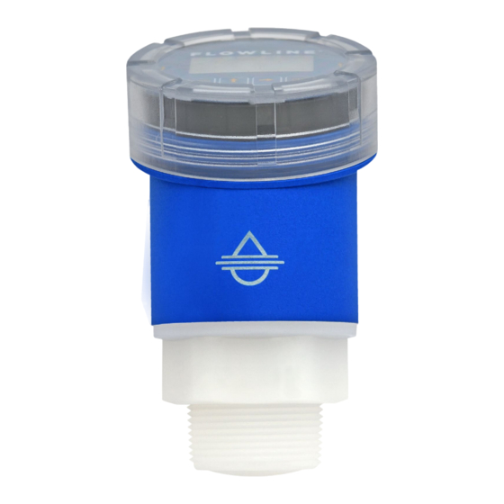
- Page 1 EchoBeam ® 80 GHz Radar Liquid & Solid Level Transmitter LR83 Series Quick Start Guide ©2023 Flowline, Inc. All Rights Reserved Flowline, Inc. | 10500 Humbolt Street, Los Alamitos, CA 90720 p 562.598.3015 f 562.431.8507 w flowline.com QS310320 Rev A...
-
Page 2: Transmitter Models
® with an advanced configuration such as open channel flow, please refer to the EchoBeam ® Manual or visit the Flowline website at www.flowline.com. WE DO YOUR LEVEL BEST ® Thank you for purchasing EchoBeam . We appreciate your business and look forward to reliably serving your level requirements, now and in the future. -
Page 3: Radio Compliance
RADIO COMPLIANCE See the Radio Addendum Supplementary Instructions for radar level measuring instruments with radio approvals at www.flowline.com regarding the safe and regulatory compliant use of this device. SAFETY AND USE The sensor is a general-purpose device and should not be used in classified hazardous environments with or near flammable or explosive media. - Page 4 Note: The Sensor PIN Code will be the 6-digit manufacturer’s date code located in the upper right corner of the label. Note: For information on using the display for configuration, see the EchoBeam ® display manual at www.flowline.com. QS310320 Rev A...
-
Page 5: Basic Configuration Overview
6) Check the Echo Curve • This tool allows you to view the echo signal returns and filter any that may be problematic. Note: For information on using the display for configuration, see the EchoBeam ® display manual at www.flowline.com. QS310320 Rev A... -
Page 6: Step 1 - Measure The Tank
STEP 1 – MEASURE THE TANK Properly locating the sensor and correctly measuring the tank sets the foundation for sensor configuration. In doing so, consider the sensor’s mounting location with respect to relevant fittings, risers, dome tops or cone bottoms, and identify where the measurements are taken from the sensor. - Page 7 TOP OF TANK CONSIDERATIONS When installing EchoBeam ® on an enclosed tank top, the installed position of the sensor’s antenna or measurement location, above or below the top, must be taken into consideration when determining your sensor configuration settings. Tank Top Installation Short Riser Installation Tall Riser Installation SENSOR OUTPUT TO LOCAL DISPLAY/CONTROLLER...
-
Page 8: Step 2 - Install The Transmitter
STEP 2 – INSTALL THE TRANSMITTER EchoBeam ® measures the air gap distance between the bottom edge of the sensor’s antenna and the liquid or solid media surface. To properly install the sensor, adhere to the following installation best practices: 1) Locate the sensor where there are no obstructions between the bottom edge of the sensor’s installed antenna and the bottom of the empty tank, including its measurement beam angle. -
Page 9: Step 3 - Wire The Transmitter
5) Install the sensor in accordance with all applicable national, state or local safety requirements such as the United States National Electrical Code (ANSI/NFPA 70) or the Canadian Electrical Code. 6) While adhering to the minimum free space requirements, based on the model, install the sensor with the following minimum distances away from the tank side walls: LR83: >... - Page 10 The Terminal (1) or Positive (+) and Terminal (2) or Negative (- ) terminals are for connection to a 12-30 VDC power supply or to a 4-20 mA loop power source. The wire to the terminals can be extended up to 1,000 feet using 16-22 gauge wire.
- Page 11 Modbus Wiring QS310320 Rev A...
- Page 12 WIRING TO DISPLAYS, CONTROLLERS & PLC’S Below are examples of how to wire EchoBeam ® to common displays, controllers and PLC’s. DataView™ LI55 Series Generic PLC Level Controller Generic Loop Powered Display DataLoop™ LI23 Series Level Indicator (With Backlight) ELECTRICAL, USAGE AND SAFETY 1.
- Page 13 Advanced. For first time configuration, we suggest using the Step-by-Step Configuration method. If you need to make any changes later, then we suggest using the Quick Adjust method. Sensors Screen Configuration Menu Note: For information on using the display for configuration, see the EchoBeam ® display manual at www.flowline.com. QS310320 Rev A...
- Page 14 Screen 1 – Basic Settings • Sensor Name o Input a unique name to identify the device (location, tank and/or media) within 12 characters. • Application o Select the type of media (liquid or solids) that the sensor will measure. •...
- Page 15 Screen 3 – Set the Fill-Height (20mA) Input the distance from the bottom of the tank to the maximum fill level, which defines the 20mA set point. Screen 4 - Set the Display Value Select the level height, air gap distance, current or percent of span value that the sensor will display.
- Page 16 STEP 6 – CHECK THE ECHO CURVE This function graphically displays the primary echo return(s) the transmitter sees, the location and amplitude of the return(s), and the numeric air gap distance from the transmitter’s measurement location to the level below. Note: This step should only be performed after having completed the prior four configuration steps and with the transmitter installed on the tank.
- Page 17 What is a Good EchoCurve? EchoCurve presents a physical representation of the return signal across the operational range for the radar transmitter. There are two components to observe when looking at the EchoCurve: • Check the Peak(s) along the EchoCurve o Ideally, there should be a significant peak which represents the liquid or solids level in the tank.
- Page 18 • Multiple peaks before or after the liquid or solids level ® o If there are multiple peaks, the EchoBeam have trouble identifying which is the correct peak (liquid or solids level). o Performing a False EchoCurve will allow the EchoBeam ®...
- Page 19 DIAGNOSTICS • False EchoCurve o Obstructions in the tank (mixer blades, side wall weld joints, material build-up, submersible pumps, piping or other apparatus), tall tank risers or installation fittings can create false signal returns that impair the transmitter’s measurement. o This function maps all echo returns within the tank, differentiating between good and false echoes.
-
Page 20: Quick Adjust
QUICK ADJUST Quick Adjust is ideal for making changes to the main level settings. It can also as a quick configuration method for experienced users of the LevelTap™ App. To access Quick Adjust, open Configuration and then select Quick Adjust. •... -
Page 21: Warranty
WARRANTY Flowline warrants to the original purchaser of its products that such products will be free from defects in material and workmanship under normal use and service in accordance with instructions furnished by Flowline for a period of two years from the date of manufacture of such products. Flowline's obligation under this warranty is...
Need help?
Do you have a question about the EchoBeam LR83 Series and is the answer not in the manual?
Questions and answers