Table of Contents
Advertisement
Quick Links
Advertisement
Table of Contents

Related Manuals for FlowLine EchoBeam LR85 Series


Summary of Contents for FlowLine EchoBeam LR85 Series
- Page 1 80 GHz Radar Liquid & Solid Level Transmitter LR83 & LR85 Series Display Manual (Addendum to LevelTap™ Manual) ©2023 Flowline, Inc. All Rights Reserved Flowline, Inc. | 10500 Humbolt Street, Los Alamitos, CA 90720 p 562.598.3015 f 562.431.8507 w flowline.com AD310320 Rev A...
-
Page 2: Table Of Contents
Introduction Section One TABLE OF CONTENTS Section One | Introduction ..................... 4 Sensor Models ...................... 4 Section Two | Getting Started ..................5 Setup Overview ....................5 Section Three | Configuration Using Display ............... 6 Using the Display ....................6 Changing Display Values .................. - Page 3 Introduction Section One Echo Threshold ..................36 Envelope Level ..................37 Damping Time ..................38 False Echo Edit ..................39 Near Band Detect ................... 41 Section Five | Diagnostics .................... 42 Entering Diagnostics Menu ................. 42 Choose Curve ..................... 43 What is a Good EchoCurve ................
-
Page 4: Section One | Introduction
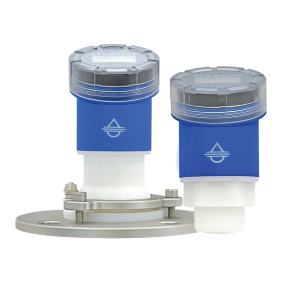
Introduction Section One SENSOR MODELS Offered in two different models, EchoBeam is an FMCW radar level sensor that provides a continuous output ® proportional to the liquid or solids level in a tank or sump. Available outputs include 4-20mA, 4-20mA w/ HART and ModBus RTU. -
Page 5: Section Two | Getting Started
Getting Started Section Two SETUP OVERVIEW The below list highlights the initial steps required to set up your transmitter for operation. Step 1: Set the Units of Measurement Select the Units of Measurement (inches, feet, millimeters, centimeters or meters) that will be used by the sensor and displayed by the App (and sensor push button display module if applicable to your model). -
Page 6: Section Three | Configuration Using Display
Configuration Using Display Section Three USING THE DISPLAY The display module features a dot matrix LCD display with 4 push buttons on a removable puck. Out of the box, the display indicates level in feet and depicts the level on a bar graph at the right side of the display. The four buttons perform the following functions: •... -
Page 7: Changing Display Values
Configuration Using Display Section Three CHANGING DISPLAY VALUES The numeric values are set using the Right Arrow and Up Arrow buttons. Press the Right Arrow button to select the next digit and the Up Arrow button to increment the digit value. The digit being changed is highlighted. -
Page 8: Measure The Tank (Basic Dimensions)
Configuration Using Display Section Three MEASURE THE TANK (BASIC DIMENSIONS) EchoBeam measures the distance between the ® sensor and the liquid or solids surface below. Measuring the tank is one of the most important aspects in configuring the transmitter. When measuring the tank, consider the location of the transmitter with respect to fittings, risers, dome tops and bottoms, and identify where the... -
Page 9: Confirm The Tank Measurements
Configuration Using Display Section Three CONFIRM THE TANK MEASUREMENTS All measurements with EchoBeam are referenced from the bottom of the transmitter. Once the transmitter ® has been installed, you may need to adjust your original measurements due to the location of the EchoBeam ®... -
Page 10: Basic Configuration Overview Using Push Button Display
Configuration Using Display Section Three BASIC CONFIGURATION OVERVIEW USING PUSH BUTTON DISPLAY Below are the 8 basic steps to configure the sensor for operation. Each step is described in detail on the following pages: Step 1: Set the Units of Measurement Select the Units of Measurement (inches, feet, millimeters, centimeters or meters) that will be used by the sensor and displayed by the App (and sensor push button display module if applicable to your model). -
Page 11: Step 1 - Set The Units Of Measurement
Configuration Using Display Section Three STEP 1 - SET THE UNITS OF MEASUREMENT This function sets the units for all measurement values to be entered into the transmitter. Options for units of measurement are inches, feet, millimeters, centimeters or meters. 1) From the Main Screen, press OK to advance into the Main Menu. -
Page 12: Step 2 - Set The Application Medium
Configuration Using Display Section Three STEP 2 - SET THE APPLICATION MEDIUM This function informs the transmitter of the media that is being measured. 1) From the Main Screen, press OK to advance into the Main Menu. 2) Press OK to advance into the Configuration Menu. 3) Press OK to advance into Basic Menu (Application screen will appear). -
Page 13: Step 3 - Set The Fail-Safe Option
Configuration Using Display Section Three STEP 3 - SET THE FAIL-SAFE OPTION This function sets the default output when EchoBeam is not able to acquire a valid return signal. ® 1) From the Main Screen, press OK to advance into the Main Menu. 2) Press OK to advance into the Configuration Menu. -
Page 14: Step 4 - Set The Sensor Height (4Ma)
Configuration Using Display Section Three STEP 4 - SET THE SENSOR HEIGHT (4MA) This function sets the Sensor Height set point for the transmitter corresponding 4mA to empty. 1) From the Main Screen, press OK to advance into the Main Menu. 2) Press OK to advance into the Configuration Menu. -
Page 15: Step 5 - Set The Fill-Height (20Ma)
Configuration Using Display Section Three STEP 5 - SET THE FILL-HEIGHT (20MA) This function sets the Fill-Height set point for the transmitter corresponding 20mA to full. 1) From the Main Screen, press OK to advance into the Main Menu. 2) Press OK to advance into the Configuration Menu. -
Page 16: Step 6 - Set The Display Value
Configuration Using Display Section Three STEP 6 - SET THE DISPLAY VALUE EchoBeam can display (on the local display or within the LevelTap™ App) either the liquid/solids level or the ® air gap above the liquid/solids. 1) From the Main Screen, press OK to advance into the Main Menu. -
Page 17: Step 7 - Set The Sensor Name
Configuration Using Display Section Three STEP 7 - SET THE SENSOR NAME This enables you to provide a unique name or identifier for each transmitter. This is the name of the transmitter that appears as the main identifier when using the LevelTap™ App. Note: It is easier to use the LevelTap™... -
Page 18: Step 8 - Check The Echocurve
Configuration Using Display Section Three STEP 8 - CHECK THE ECHOCURVE EchoCurve presents a physical representation of the return signal across the operational range for the radar transmitter. From the Main Screen, press ESC to view the EchoCurve. There are two components to observe when looking at the EchoCurve: Check the Peak(s) along the EchoCurve •... -
Page 19: Section Four | Advanced Configuration Using Display
Advanced Configuration Using Display (Range Adjust) Section Four ADVANCED ADJUSTMENTS OVERVIEW These optional functions are used to change the transmitter output characteristics. Note: These adjustments should only be performed after having completed the configuration steps previously described with the transmitter installed on the tank. Where so, perform the following applicable Advanced Adjustments. -
Page 20: Dead Band
Advanced Configuration Using Display (Range Adjust) Section Four DEAD BAND This setting defines the minimum distance that the EchoBeam will detect valid echo returns. EchoBeam ® ® will not read a level above this setting. All values will be in the Units previous defined during configuration. Default setting will be at 90% of the difference between the Sensor Height and Fill-Height values. - Page 21 Advanced Configuration Using Display (Range Adjust) Section Four While the Dead Band setting is typically configured to be at the same level as Fill-Height, they are completely independent settings. Dead Band Equals Fill-Height In this example, the Dead Band is located at the same level as the Fill- Height setting.
-
Page 22: Maximum Range
Advanced Configuration Using Display (Range Adjust) Section Four MAXIMUM RANGE This setting defines the maximum distance that the sensor will detect valid echo returns. EchoBeam will not ® read a level beyond this setting. All values will be in the Units previously defined during configuration. Suggested setting will be 105% greater than the Sensor Height value. -
Page 23: Reverse Ma
Advanced Configuration Using Display (Range Adjust) Section Four REVERSE MA This function sets the current output at either 4-20 mA or 20-4 mA. Selecting 4-20 mA sets the output with 4mA @ bottom and 20mA @ top of the tank. This is the standard output used in most applications. Selecting 20-4 mA sets the output with 20mA @ bottom and 4mA @ top of the tank. -
Page 24: Distance Adjust
This function allows the factory set distance of a measured value to be adjusted. Note: This function should only be performed by a trained technician. Never change this setting unless instructed by a Flowline representative. Be sure to record this setting if a Factory Reset is performed. -
Page 25: Hart
Advanced Configuration Using Display (HART) Section Four ADVANCED ADJUSTMENTS OVERVIEW - HART HART supports an operation mode capable of supporting multiple HART instruments on the same pair of wires. This is known as multidrop mode. A unique address number must be assigned to each device to differentiate one sensor from another. -
Page 26: Hart
Note: This function should only be performed by a trained technician. Never change this setting unless instructed by a Flowline representative. Be sure to record this setting if a Factory Reset is performed. 1) From the Main Screen, press OK to advance into the Main Menu. -
Page 27: Level Variables
Advanced Configuration Using Display (Level Variables) Section Four PROCESS ADJUSTMENTS OVERVIEW (LEVEL VARIABLES) These optional functions are intended to improve transmitter performance in applications with the below process and/or installation characteristics. Note: These adjustments should only be performed when (after having completed the configuration steps previously described with the transmitter installed on the tank) the transmitter is not performing to your satisfaction. -
Page 28: Low Dielectric
Advanced Configuration Using Display (Level Variables) Section Four LOW DIELECTRIC Used when measuring a medium with a low dielectric constant and the reflection from the bottom of the tank is stronger than the medium reflection. Selections are YES or NO with the Default being NO. If YES is selected, then enter the Empty Span value (distance from tank bottom to the bottom of the sensor) so the transmitter can filter out the tank bottom. -
Page 29: Turbulent Or Agitated Surface
Advanced Configuration Using Display (Level Variables) Section Four TURBULENT OR AGITATED SURFACE If the liquid surface is turbulent or agitated, set Turbulent Surface to Yes. Note: Turbulent or agitated surfaces can occur when tanks are filled from the top without a down pipe, or when a mixer or air agitation is used within the tank. -
Page 30: Fast Filling Or Emptying
Advanced Configuration Using Display (Level Variables) Section Four FAST FILLING OR EMPTYING If the speed of liquid level rise or fall within the tank is greater than a rate of 1” per second (25.4mm/sec), set Fast Level Change to YES. Note: Fast filling or emptying can occur when multiple pumps are operating or when a weather event increases the amount of liquid entering the tank. -
Page 31: Multiwave
Advanced Configuration Using Display (Level Variables) Section Four MULTIWAVE Used when there are multiple return echoes displayed in the EchoCurve. 1) From the Main Screen, press OK to advance into the Main Menu. 2) Press OK to advance into the Configuration Menu. -
Page 32: Signal Properties
Advanced Configuration Using Display (Signal Properties) Section Four PROCESS ADJUSTMENTS OVERVIEW These optional functions are intended to improve transmitter performance in applications with the below process and/or installation characteristics. Note: These adjustments should only be performed when (after having completed the configuration steps previously described with the transmitter installed on the tank) the transmitter is not performing to your satisfaction. -
Page 33: First Echo
Advanced Configuration Using Display (Signal Properties) Section Four FIRST ECHO Used when the sensor has difficulty seeing the first echo return. This setting adjusts the peak strength (dB) of the first echo. Default is Normal. The settings are listed below: Normal –... -
Page 34: Echo Lost Timeout
Advanced Configuration Using Display (Signal Properties) Section Four ECHO LOST TIMEOUT Sets the length of time the transmitter will look for a valid reading. If the time set is passed, the output will switch to the Fail-Safe setting. When this occurs, the display will show E14 (no signal). Time value can be set from 1 to 10000.0 seconds. -
Page 35: False Echo Memory
When done, press ESC to return to the Signal Properties Menu, press ESC to return to the Advanced Menu, press ESC again to return to the Configuration Menu and press ESC a fourth time to return to the Main Screen. Note: Flowline suggests setting False Echo Memory value to 0.95 x Valid Distance Value. AD310320 Rev A... -
Page 36: Echo Threshold
Advanced Configuration Using Display (Signal Properties) Section Four ECHO THRESHOLD Echo Threshold and Envelope Level are both tied to the Envelope. Echo Threshold is the difference the return signal must exceed above the Envelope so that the return signal can be considered a valid level (liquid or solids). -
Page 37: Envelope Level
Advanced Configuration Using Display (Signal Properties) Section Four ENVELOPE LEVEL Echo Threshold and Envelope Level are both tied to the Envelope. Envelope Level is the difference between the EchoCurve, and the actual Envelope, and it adjusts with the shape of the EchoCurve. Envelope Level is in units of dB. -
Page 38: Damping Time
Advanced Configuration Using Display (Signal Properties) Section Four DAMPING TIME This function sets the sampling rate for which the sensor updates the current output. The value is entered in seconds with a default of 20 seconds. Decreasing the value will make the output more responsive to level changes. -
Page 39: False Echo Edit
Advanced Configuration Using Display (Signal Properties) Section Four FALSE ECHO EDIT Allows for any identified False Echo to be edited. Use this setting after a False EchoCurve has been created. Enter the starting point distance, starting point intensity (dB), end point distance, and end point intensity (dB) according to the menu prompts. - Page 40 Advanced Configuration Using Display (Signal Properties) Section Four 7) Press Right Arrow (at least six times) to scroll to False Echo Edit. 8) Press OK to edit the False EchoCurve. 9) Enter the Starting Point Distance (Start) using the Up Arrow and Right Arrow.
-
Page 41: Near Band Detect
Advanced Configuration Using Display (Signal Properties) Section Four NEAR BAND DETECT This function is used when level is close to the bottom of the sensor. When enabled, the EchoBeam will use an alternative algorithm to determine the actual level within 3.28 ft (1m) from the transmitter. Note: the alternative algorithm will ignore the envelope within this window. -
Page 42: Section Five | Diagnostics
Diagnostics Section Five The features below are used to view EchoCurve, False EchoCurve, activate a simulation or observe the sensor’s status. Choose Curve • This setting enables the selection of the standard EchoCurve or the False EchoCurve for viewing. Simulation •... -
Page 43: Choose Curve
Diagnostics Section Five CHOOSE CURVE This function allows the selection to view either the EchoCurve (default) or the False EchoCurve. The EchoCurve graphically displays the primary echo return(s) the transmitter sees, the location and amplitude of the return(s), and the numeric air gap distance from the bottom of the transmitter to the level below. The False EchoCurve graphically displays the echoes which are removed from consideration as acceptable media return signals. - Page 44 Diagnostics Section Five 1) From the Choose Curve (2.1) screen, press OK to enter Choose Curve. 2) Select either EFF Curve or False Echo. a. Press Up Arrow or Right Arrow to toggle between the two curves. b. Press Right Arrow to move one segment to the right. Right Arrow will scroll left to right and then back to the first segment.
-
Page 45: What Is A Good Echocurve
Diagnostics Section Five WHAT IS A GOOD ECHOCURVE? EchoCurve presents a physical representation of the return signal across the operational range for the radar transmitter. There are two components to observe when looking at the EchoCurve: Check the Peak(s) along the EchoCurve •... - Page 46 Diagnostics Section Five WHAT IS A BAD ECHOCURVE? Multiple peaks before or after the liquid or solids level • o If there are multiple peaks, the EchoBeam ® may have trouble identifying which is the correct peak (liquid or solids level). o Performing a False EchoCurve will allow the EchoBeam to filter out the false signals.
-
Page 47: Simulation
Diagnostics Section Five SIMULATION Simulate various level conditions by manually adjusting the output of EchoBeam . This can be used to ® confirm functionality of a system without having to wait for the level in the tank to rise or fall to a specific level. For example, if you need a high alarm to activate at 95%, you can use Simulate to output the •... -
Page 48: Sensor Status
Diagnostics Section Five SENSOR STATUS View all values measured by the transmitter including: (T) Temperature – Internal temperature of the transmitter • DB – Value is in dB with a range from 0 to 150 • Volt – The voltage being read by the sensor •... -
Page 49: Section Six | Data Sampling
Data Sampling Section Six DATA SAMPLING EchoBeam can sample the last 1,000 data points as well as the last 10 EchoCurves. The data and the ® EchoCurves can be exported for review with the use of the LevelTap™ App. These values are stored in the memory of the transmitter following a first in, first out logic. -
Page 50: Entering Data Sampling Menu
Data Sampling Section Six ENTERING DATA SAMPLING MENU To enter Data Sampling, follow below: 1) From the Main Screen, press OK to advance into the Main Menu. 2) Press Right Arrow twice to move the triangle to Data Sampling. 3) Press OK to advance into Data Sampling. 4) Use the Right Arrow and Up Arrow screens to toggle between the Enable Log (3.1), Distance Log Interval (3.2), Curve Log Interval (3.3), View Distance Log (3.4), View Curve log (3.5) and Reset Log Data (3.6) screens. -
Page 51: Distance Log Interval
Data Sampling Section Six DISTANCE LOG INTERVAL Use this feature to set the time interval for each sample. Up to 1,000 points will be stored following the first in, first out protocol. Distance Log Interval can be set from a minimal interval of 5 seconds to a maximum interval of 24 hours. -
Page 52: Curve Log Interval
Data Sampling Section Six CURVE LOG INTERVAL Use this feature to set the time interval between each EchoCurve sample. Up to 10 EchoCurves will be stored following the first in, first out protocol. Curve Log Interval can be set from a minimal interval of 3 minutes to a maximum interval of 24 hours. -
Page 53: View Curve Log
Data Sampling Section Six VIEW CURVE LOG Use this feature to view the stored EchoCurves. Use the Right Arrow and Up Arrow to toggle between the various EchoCurves (up to 10 will be stored). Data on an EchoCurve is shown with the X-axis representing distance away from the sensor and the Y-axis representing the strength of the signal. -
Page 54: Section Seven | Information
Information Section Seven INFORMATION These features are used to provide enhanced information about the EchoBeam , to change the language ® shown on the display, and to reset the device. Information • Lists the basic information for the EchoBeam® including the product type (Type), the serial number (ID) and the Production Date (PD). -
Page 55: Entering Information Menu
Information Section Seven ENTERING INFORMATION MENU To enter Information, follow below: 1) From the Main Screen, press OK to advance into the Main Menu. 2) Press Right Arrow three times to move the triangle to Information. 3) Press OK to advance into Information. 4) Use the Right Arrow and Up Arrow to toggle between the Information (4.1), Software Version (4.2), Write Protect (4.3), Language (4.4), Reset (4.5) and BLE Password (4.6) screens. -
Page 56: Write Protect
Information Section Seven WRITE PROTECT Enables the sensor to be protected with a 6-digit security code. The code prevents the changing of parameters without entering the code prior to making any change. Note: This function should only be performed by a trained technician. The code must be stored in a safe location. -
Page 57: Reset
Information Section Seven RESET Enables all the sensor’s settings to be returned to the factory settings. If this feature is enacted, you will need to re-configure the device for operation in the application. 1) From the Information (4.1) screen, press Right Arrow (four times) to switch to Reset. -
Page 58: Section Eight | Troubleshooting
Troubleshooting Section Eight TROUBLESHOOTING OVERVIEW Problem Solution Transmitter output is Check wiring for open circuit. between 0mA to 3.9mA Check the installation of the transmitter. Bad installation fittings will cause Transmitter jumps to a false signals near the top of the tank, which typically translates to a signal current reading between 19 between 19 and 20 mA. -
Page 59: Error Codes: 4-20Ma/Hart With Display
Troubleshooting Section Eight ERROR CODES – 4-20MA/HART WITH DISPLAY Error Code Display Code Error Definition Display communication error. Typically appears when display module is CommErr not attached correctly. May also indicate communication error between the display and the main electronics. ROM write error. -
Page 60: Section Nine | Appendix
Appendix Section Nine FACTORY SETTINGS Below are the Sensor Height (4mA) and Fill-Height (20mA) factory settings for each sensor. Sensor Name LR83 LR85 Application Liquids Solids Units of Measurement Fail-Safe Output 20.5mA 20.5mA Sensor Height 98.42 ft 393.7 ft Fill-Height 97.42 ft 392.7 ft Display Value... -
Page 61: Modbus Output Definitions
Appendix Section Nine MODBUS OUTPUT DEFINITIONS Communication Parameters: Hardware interface: RS485 Baud rate: 9600 Modbus RTU: 8, N, 1 Error Checking: CRC16 polynomial A001 Default Address: Modbus function codes supported: Function 03 - Read Register/s Function 06 - Write Single Register Examples: Function 03 - Read Register/s Read Registers - Address = 1, starting from register 00H through 0AH (10 registers) - Page 62 Appendix Section Nine Register Mapping: 0x0000 Distance measurement in centimeters (read only) 0x0001 Distance measurement in millimeters (read only) 0x0002 Level measurement in centimeters (read-only) 0x0003 Level measurement in millimeters (read-only) 0x0004 Measurement status (read-only); = Normal = Comm Err - Display not connected or broken = EEProm Err - write failure, EEPROM is broken = PLL Err - antennae circuit is broken = SYSBUSY - Slow response due to large data request or low supply voltage...
-
Page 63: Section Ten | Warranty, Returns And Limitations
Step Ten WARRANTY Flowline warrants to the original purchaser of its products that such products will be free from defects in material and workmanship under normal use and service in accordance with instructions furnished by Flowline for a period of two years from the date of manufacture of such products. Flowline's obligation under this...
Need help?
Do you have a question about the EchoBeam LR85 Series and is the answer not in the manual?
Questions and answers