Table of Contents
Advertisement
Quick Links
Advertisement
Table of Contents

Related Manuals for IKA RC 5 control


Summary of Contents for IKA RC 5 control
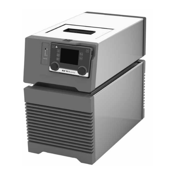
- Page 1 IKA RC 5 control Operating instructions...
-
Page 2: Device Setup
Device setup Fig. 1 Item Designation Filling opening lid Wireless Controller (WiCo) Handle Venting grid RS 232 port USB port External temperature sensor socket Multifunction port Pump connector IN Pump connector OUT Power switch Power socket Backflow Overflow... -
Page 3: Table Of Contents
Inserting battery into the WiCo ����������������������������������������������������������������������������������������������������������������������� 9 Mounting the WiCo to the station ������������������������������������������������������������������������������������������������������������������� 9 Filling and draining ������������������������������������������������������������������������������������������������������������������������������������������� 9 Fluids (Standard information for IKA fluid) ����������������������������������������������������������������������������������������������������� 11 Moving the device ����������������������������������������������������������������������������������������������������������������������������������������� 12 Charging the Battery Pack RB 1 (rechargeable battery) ������������������������������������������������������������������������������������ 12 Changing battery to WiCo �����������������������������������������������������������������������������������������������������������������������������... -
Page 4: Eu Declaration Of Conformity
Directive: 2014/53/EU Standards: EN 300328, EN 301489-17, EN 301489-1, EN 60950-1 A copy of the complete EU Declaration of Conformity can be requested at sales@ika�com� Note for USA (FCC) This equipment complies with Part 15 of the FCC rules� Any changes or modifications not expressly approved by the Manufacturer could void the user's authority to operate the equipment�... -
Page 5: Safety Instructions
Disposal of the device: • Process pathogenic material only in closed vessels under • The device must be disposed of in accordance with na- a suitable fume hood� Please contact IKA application tional or local regulations support if you have any question�... -
Page 6: Fluids
- Ferrous water� cause a fire� • The lithium polymer battery pack must only be used and Refrigerant: charged in IKA products designed for use with this bat- The device is not allowed to be tery pack� WARNING used in an ATEX (Atmosphere EX- •... -
Page 7: Disposal Instructions
The safety of the user cannot be guaranteed: fluids� - If the device is operated with accessories that are not supplied or recommended by the IKA� Range of use: - If the device is operated improperly or in contrary to the Indoor environments similar to that a laboratory of re- IKA specifications�... -
Page 8: Unpacking
Unpacking Unpacking: Delivery scope: - Please unpack the device carefully� - RC 5 control with WiCo - Any damage should be notified immediately to the shipping - Power cables agent (post office, railway network or logistics company)� - Hose olive NW 8 (2 pieces) see Fig�... -
Page 9: Inserting Battery Into The Wico
Check fluid heat expansion! - Connect the “Backflow” connection to IKA calorimeter with a suitable hose� When IKA calorimeter is not connected, please close the “Backflow” connection with included backflow cap� External system Note: If the WiCo need be permanently attached to the station, we strictly recommend to fasten the unlocking button with the integrated screw (turn counter clock wise)�... - Page 10 - Check and make sure that the drain valve is closed (ro- - To drain the fluid from the bath, connect a hose to the tate clockwise to the stop position, see Fig� 10)� drain port and turn the drain valve in counter clockwise direction with a straight screwdriver�...
-
Page 11: Fluids (Standard Information For Ika Fluid)
Fluid (Standard information for IKA fluid): Operating temperature Operating temperature Safety temperature Flash point Designation range for open bath range for closed bath (°C) (°C) application applications (°C) (°C) CF�EG28�N10�80�8 -10 ��� 80 -10 … 80 CF�EG39�N20�80�16 -20 … 80 -20 …... -
Page 12: Moving The Device
Moving the device: Empty all fluid in the bath before move device from one place to other place� The device must be lifted by two persons with the upper handles� It can also be moved on flat surface by lifting and pushing the front of the device�... -
Page 13: Operator Panel And Display
Operator panel and display station: High Fluid level Fig. 16 Item Designation Function Fluid level indicator: Indicate the bath fluid level (when the fluid level is too low or too high, the bottom or the top LED segment change into red color)� LED bar: Display different status of the circulator with different color�... -
Page 14: Commissioning And Operating
Commissioning and operating Note: Before commissioning, make sure that the device has Then the working screen appears and the device is ready not been moved for one hour! for operation� Check whether the voltage given on the type plate cor- responds to the available power voltage�... -
Page 15: Useful Information
Useful information The station is controlled via a WiCo� If the WiCo is Depending on the structure of the building, the WiCo can mounted on the station, data is exchanged between the be operated at a distance up to 15 m from the station, station and WiCo via the contacts (C)�... -
Page 16: Menu Navigation And Structure
Battery pack: Pump: This symbol indicates the charging status of the RB 1 bat- This symbol indicates that the pump is activated� tery pack within the WiCo� The charging symbol appears if the WiCo Warning: - Is connected to a PC via a USB cable This symbol indicates that warning is active�... - Page 17 Menu structure: Factory Settings TEMPERING Control Control Mode Internal (int) activated External (ext) Control Parameters Automatic activated Manual Internal (Kp, Ti, Td, Ts, Prop_Bp, Prop_Bn) 3.0, 20.0, 2.0, 3s, +2.00, -1.00 External (Kp, Ti, Td, Ts, Prop_Bp, Prop_Bn) 3.0, 20.0, 2.0, 3s, +2.00, -1.00 Information (Kp, Ti, Td, Ts, Prop_Bp, Prop_Bn) Fluids CF.EG28.N10.80.8...
-
Page 18: Menu (Details)
Ti-values that are too small temperature� See table in the section “Fluids (Standard in- can lead to instability of the controller� formation for IKA fluid)“� Td: Differential time The maximum and minimum temperature values of the The differential time Td (s) is the derivative time and de- selected fluid can be set within these limitations�... - Page 19 3� Temperature sensor: 1) Calibration: The internal and external temperature measurement can be calibrated and adjusted� You can select 2-point calibration or 3-point calibration for internal and external measurement� Calibration proceeding (example: 2-point calibration): > Temperature Sensor > Calibration > Calibration > Internal >...
- Page 20 MODE PROGRAMS Under programs, 10 user-defined temperature-time pro- 1� Operating Mode A: files can be created� A program can consist of up to 10 After power-on/power failure no automatic restart of segments� functions� Once a program has been selected, the following options are available: 2�...
- Page 21 Edit: Edit/change the selected program parameters� Note: Prior to using the “Refill” menu option, check the function of the buoyage� Delete: Delete the selection highlighted in yellow pro- The “Refill” menu option has higher priority than the pro- gram segment� gram M1 segment settings�...
- Page 22 SAFETY SETTING 1� Time out: 1� Languages: The “Language“ option allows the user to select the de- 1) Set: sired language� In the menu “Set”, the user can determine a time limit in the event of a communication breakdown between the 2�...
-
Page 23: Interface And Output
1�1)� The NAMUR commands and the additional specific IKA co mmands serve only as low level commands for communication between the device and the PC� With a suitable terminal or communications programme these commands can be transmit- ted directly to the circulator equipment�... - Page 24 IN_TMODE Read temperature control: (0: internal control) (1: external control) OUT_SP_1 xxx Set the internal setting temperature XXX (if 0: internal control) Set the external setting temperature XXX (if 1: external control) OUT_SP_12@n Set the WD safety temperature with echo of the set (defined) value� OUT_SP_4 xxx Set the pump speed XXX OUT_SP_42@n...
- Page 25 Connection WiCo to station: USB micro B USB micro A USB micro B USB micro A USB cable Fig. 31 Connection the device to PC: 9-pin RS 232 9-pin RS 232 RS 232 USB micro B USB A USB micro B USB A USB micro B USB A...
-
Page 26: Maintenance And Cleaning
For repair, please request the “Decontamination Certifi- cate” from IKA, or download printout of it from the IKA Note: Don’t touch the heating exchanger surface with website www�ika�com�... -
Page 27: Error Codes
Error codes Any malfunctions during operation will be identified by an error message on the display� Proceed as follows in such cases: Switch off device using the main switch at the back of the device� Carry out corrective measures� ... -
Page 28: Accessories
PUR tube (nominal width 8 mm) H�PUR�12 PUR tube (nominal width 12 mm) Additional accessories: H�FKM�8 FKM tube (nominal width 8 mm) PC 1�1 Cable (RS 232) H�FKM�12 FKM tube (nominal width 12 mm) Labworldsoft ® See more accessories on www�ika�com�... -
Page 29: Technical Data
Technical data Nominal voltage 230 ± 10% 100 ��� 115 ± 10% Frequency 50 / 60 Max� input power 1100 Working temperature range °C - 30 ��� RT Operating temperature range (with external heating) °C - 30 ��� + 80 Temperature stability –... - Page 30 WiCo Permitted on time Max� communication distance (dependent on the building) Dimensions (W x D x H) 160 x 40 x 105 Weight 0�3 Ambient temperature + 5 ��� + 40 Ambient humidity (relative) IP code according to EN 60 529 IP 40 Interface RB 1 Battery pack...
-
Page 31: Warranty
Warranty In accordance with IKA warranty conditions, the warranty The warranty does not cover worn out parts, nor does it period is 24 months� For claims under the warranty please apply to faults resulting from improper use, insufficient contact your local dealer� You may also send the machine... - Page 32 VIETNAM IKA Vietnam Company Limited Phone: +84 28 38202142 eMail: sales�lab-vietnam@ika�com Discover and order the fascinating products of IKA online: www�ika�com IKAworldwide IKAworldwide /// #lookattheblue @IKAworldwide Technical specifications may be changed without prior notice�...
Need help?
Do you have a question about the RC 5 control and is the answer not in the manual?
Questions and answers