IKA EUROSTAR 20 Manual
High speed control
Hide thumbs
Also See for EUROSTAR 20:
- Operating instructions manual (236 pages) ,
- User manual (108 pages) ,
- User manual (12 pages)
Table of Contents
Advertisement
Quick Links
Advertisement
Table of Contents

Related Manuals for IKA EUROSTAR 20


Summary of Contents for IKA EUROSTAR 20
- Page 1 20000003967a EUROSTAR_092016 ® EUROSTAR 20 high speed control...
- Page 2 EUROSTAR Wireless Controller station (WiCo) Fig. 2 Fig. 4 Fig. 1 Fig. 3 RS 232 Temp. Sensor Fig. 5 Fig. 6 Fig. 7 Fig. 8...
-
Page 3: Table Of Contents
Drive Error codes Motor protection Warranty Speed – normal operation Accessories Speed – overload operation Permitted IKA ® stirrer tools Output shaft Technical data Speed display Declaration of conformity We declare under our sole responsibility that this product corresponds to the regulations 2014/35/EU, 2006/42/EC, 2014/30/EU and 2011/65/ EU and conforms with the standards or standardized documents EN 61010-1, EN 61010-2-051, EN 61326-1, EN 60529 und EN ISO 12100. -
Page 4: Safety Instructions
fire or explo- - projectile parts sions or comprehensive monitoring equipment. Furthermore, users - body parts, hair, clothing and jewelry getting caught. must make sure that the OFF switch of the IKA ® product can be Beware of the risk of: accessed immediately, directly and without risk at any time. -
Page 5: Correct Use
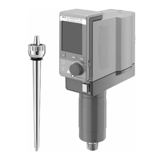
- An open-end wrench - A hook spanner • Delivery scope - A protective cover - EUROSTAR 20 high speed control stirrer with a Wireless Controller - A warranty card (WiCo) - OS 1.0 power supply unit - An operating instructions - USB cable micro A –... -
Page 6: Drive
OS 1.0 power supply unit (for Wireless Controller (WiCo)) Adapter Adapter Adapter Adapter Europe, Switzerland USA, China England Australia Drive The rotary knob (B, see Fig. 1) of the Wireless Controller (WiCo) allows the speed of the stirrer to be adjusted over the entire speed range. Motor protection The stirring instrument is suitable for continuous operation. -
Page 7: Securing
Fig. 6. Slide the R 6000 precision shaft (P) into the conical attachment on Once the EUROSTAR 20 high speed control has been connected the output shaft (N). Tighten the retaining nut (O) using a hook span- to the PC using the USB data cable, it will then transmit information ner and a single open-end wrench. -
Page 8: Switching On The Instrument
LED (F, see Fig. 1) on the stirrer (station) will light up. Useful information The EUROSTAR 20 high speed control stirrer is controlled via a The Wireless Controller can be attached to the stirrer (station), or Wireless Controller (WiCo). If the Wireless Controller is attached to... - Page 9 Working screen at the time of delivery: Home: The start screen appears for a few seconds after the This symbol means that the Wireless Controller is connected to the Wireless Controller is switched on. The device name EUROSTAR station and is communicating with the EUROSTAR Torque: Back Reset Torque...
- Page 10 Menu structure Factory settings Stirring Speed Limit ………………………………………………………………………… 6000 rpm Torque Limit ……………………………………………………………..………… 20 Ncm Torque Display ……………………………………………………………………… activated Intermittent Mode Run/Stop …………………………………..- Interval Run Time…..…………... 00:00 [mm:ss] Stop Time………………. 00:00 [mm:ss] Torque Calibration…………………………………………………………..... - Temperature Probe Temperature……………………………………………………………… - Display……………………………………………………………………………..
- Page 11 The ”Speed Limit” menu allows the user to set the desired maximum The ”Torque Display” menu allows the user to specify that the upper speed limit for the EUROSTAR 20 high speed control stirrer. torque is shown in the display. A tick shows that the option is acti- The initial setting is the maximum permissible speed of the stirrer.
- Page 12 Edit: When the highlighted "edit" symbol appear on the right top of the Operating Mode: screen, the user could change the speed (rpm), time value or inter- Operating Mode A: mittent mode setting. In this operating mode, the set speed is not saved when the current Note: The speed (rpm) value can be changed during the speed limit run comes to an end or the device is switched off.
- Page 13 Example for editing the program: PROGRAM 1 PROGRAM 1 Programs Programs Programs Time Interm. Time Interm. hh:mm Mode hh:mm Mode Program 1 Program 1 Program 1 00:00 00:00 Program 2 Program 2 Program 2 Program 3 Program 3 Program 3 Program 4 Program 4 Program 4...
-
Page 14: Interfaces And Outputs
- Commands are generally sent from the computer (Master) to the face from http://www.ika.com/ika/lws/download/usb-driver.zip and stirrer machine (Slave). install the driver by running the setup file. Then connect the IKA ® - The stirrer machine sends only at the computer’s request. Even fault vice through the USB data cable to the PC. - Page 15 IN_SP_6 Read the speed limit value ment, rev. 1.1). IN_SP_8 Read the safety speed value The NAMUR commands and the additional specific IKA ® co mmands OUT_SP_4 Adjust the rated speed value serve only as low level commands for communication between the...
-
Page 16: Maintenance And Cleaning
When ordering spare parts, please give: - machine type Cleaning - serial number, see type plate - item and designation of the spare part see www.ika.com, For cleaning disconnect the main plug! spare parts diagram and spare parts list - Software version. -
Page 17: Warranty
Warranty In accordance with IKA ® warranty conditions, the warranty period is The warranty does not cover worn out parts, nor does it apply to 24 months. For claims under the warranty please contact your local faults resulting from improper use, insufficient care or maintenance dealer. -
Page 18: Technical Data
IP 40 Protection class Excess voltage category Contamination level Protection at overload yes / motor current limitation Fuse (on mains plate) T 4 A (IKA ® Ident. No. 2585100) Ambient temperature °C + 5 ... + 40 Ambient humidity (rel.)
Need help?
Do you have a question about the EUROSTAR 20 and is the answer not in the manual?
Questions and answers