Table of Contents
Advertisement
SERVICE MANUAL
A80UH1EX & 80G1UHEX Gas Furnace
This is a safety alert symbol and should never be ignored. When you see this symbol on labels or in manuals, be alert to
the potential for personal injury or death.
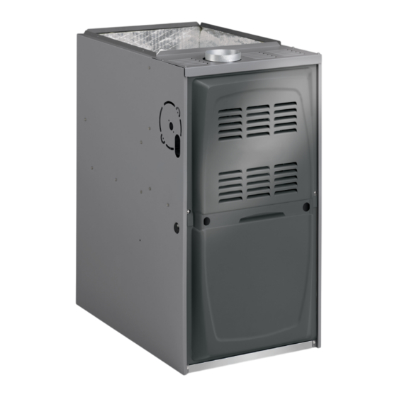
A80UH1EX & 80G1UHEX series units are mid-efficiency
gas furnaces used for upflow or horizontal applications
only, manufactured with heat exchangers formed of
aluminized steel. A80UH1EX & 80G1UHEX units are
available in heating capacities of 40,000 to 100,000 Btuh
and cooling applications 2 to 5 tons. Refer to Engineering
Handbook for proper sizing.
A80UH1EX & 80G1UHEX model units are equipped with a
hot surface ignition system. The A80UH1EX & 80G1UHEX
units meet the new California 14 ng/J Nitrogen Oxides
(NOx) Standards and California Seasonal Efficiency
requirements. All units use a redundant gas valve to assure
safety shut-off as required by C.S.A.
All specifications in this manual are subject to change.
Procedures outlined in this manual are presented as a
recommendation only and do not supersede or replace
local or state codes. In the absence of local or state codes,
the guidelines and procedures outlined in this manual
(except where noted) are recommended only and do not
constitute code.
Improper installation, adjustment, alteration, service
or maintenance can cause property damage, personal
injury or loss of life. Installation and service must be
performed by a licensed professional HVAC installer (or
equivalent), service agency or the gas supplier.
As with any mechanical equipment, contact with sharp
sheet metal edges can result in personal injury. Take
care while handling this equipment and wear gloves
and protective clothing.
508031-02
WARNING
CAUTION
Table of Contents
Technical Specifications ..............................................2
Blower Performance ....................................................3
Parts Arrangement.......................................................5
Unit Components .........................................................6
Placement and Installation ........................................16
Start-Up .....................................................................16
Heating System Service Checks ...............................16
Typical Operating Characteristics ..............................20
Maintenance ..............................................................21
Wiring and Sequence of Operation ...........................24
Operation ...................................................................29
Electric shock hazard.
Can cause injury or death. Before attempting
to perform any service or maintenance,
turn the electrical power to unit OFF at
disconnect switch(es). Unit may have
multiple power supplies.
*P508031-02*
Issue 2135
WARNING
(P) 508031-02
Page 1 of 29
Advertisement
Table of Contents
Troubleshooting

Related Manuals for Allied A80UH1EX


Summary of Contents for Allied A80UH1EX
-
Page 1: Table Of Contents
Unit Components ............6 Handbook for proper sizing. Placement and Installation ........16 Start-Up ..............16 A80UH1EX & 80G1UHEX model units are equipped with a Heating System Service Checks .......16 hot surface ignition system. The A80UH1EX & 80G1UHEX Typical Operating Characteristics ......20 units meet the new California 14 ng/J Nitrogen Oxides Maintenance ..............21... -
Page 2: Technical Specifications
Technical Specifications Physical and Electrical Data Max. Time Approx Nominal Volts/ Nominal Input Output AFUE Delay Trans Shipping Model Cooling Inlet Full Load (Btuh) (Btuh) (ICS) Breaker or (VA) Weight Capacity (in.) Phase Amps Fuse (lbs) A80UH1E040A12X 40,000 32,700 3 Ton 120-60-1 80G1UHE040A12X A80UH1E060A12X... -
Page 3: Blower Performance
Blower Performance A80UH1EX / 80G1UHEX 040A*12 Performance (less filter) Air Volume / Watts at Various Blower Speeds External Static High Medium-High Medium Medium-Low Pressure in. w.c. Watts Watts Watts Watts Watts 0.00 1430 1200 1025 0.10 1395 1165 1005 0.20... - Page 4 A80UH1EX / 80G1UHEX 100C*20 Performance (less filter) Air Volume / Watts at Different Blower Speeds Bottom Return Air, Side Return Air with Optional Return Air Single Side Return Air − Air volumes in bold require field fabricated External Base, Return Air from Both Sides or Return Air from Bottom and transition to accommodate 20 x 25 x 1 in.
-
Page 5: Parts Arrangement
Parts Arrangement Heat Exchanger Combustion Air Inducer Gas Valve Intake Screen Intake Air Elbow Control Box (includes integrated control, interlock switch and transformer) Access Panel Blower Assembly Power Choke (4 and 5 Ton Only) Figure 1. 508031-02 Issue 2135 Page 5 of 29... -
Page 6: Unit Components
Integrated Control (A92) Unit Components WARNING A80UH1EX & 80G1UHEX unit components are shown in Figure 1. The gas valve, combustion air inducer and Shock hazard. burners can be accessed by removing the upper access Disconnect power before servicing. Control is not field panel. - Page 7 Pin # Function 1/4” Quick Connect Terminals Combustion Air Inducer Line 120HUM Humidifier 120VAC Ignitor Line LINE 120VAC Combustion Air Inducer Neutral XFMR Transformer 120VAC Ignitor Neutral CIRC Indoor blower 120VAC Table 1. 4-Pin Terminal Designation Indoor air quality accessory 120VAC NEUTRALS Common 120VAC Pin #...
- Page 8 Red LED Flash Code Diagnostic Codes / Status of Furnace No power to control or board fault detected Heartbeat Control powered - displayed during all modes of operation if no errors are detected Continuous Rapid Flash Call For Heat / Burner Operation 1 flash Reverse line voltage polarity 2 flashes...
- Page 9 5 SEC Trial for Blower Post Ignitor Warm-up Pre-Purge Ignition Purge “On” Delay Demand Ignitor Gas Valve Indoor Blower * Blower on time will be 30 seconds after flame is sensed. Blower off time will depend on “OFF TIME” setting. Figure 4.
- Page 10 Air Gas Plenum Burner Gasket Gas Valve Sensor Ignitor Gas Manifold Gas Orifice Air Orifice Intake Air Screen Thermal Intake Air Switch Elbow (location) Figure 6. Heating Components Thermal Switch (Figure 6) passed through the flame and sensing electrode. The control allows the gas valve to remain open as long as The auto-reset switch is located on the front of the intake flame signal is sensed.
- Page 11 Combustion Air Inducer (B6) All A80UH1EX & 80G1UHEX units use a combustion air inducer to move air through the burners and heat exchanger during heating operation. The blower uses a 120VAC motor. The motor operates during all heating operation and is controlled by integrated control A92.
- Page 12 Test 1 Remove 5-pin plug from control Check ohms reading across terminals 1and 5 Ohm value should be between 39 - 70. Meter (set to ohms) Integrated control detail Test 2 Seperate the 2-pin jack plug near the manifold and check resistance of the ignitor. If the reading is correct, then then there is a problem with the wiring between the jack plug and control.
- Page 13 Each blower is statically and dynamically balanced as an assembly before installation in the unit. A80UH1EX & 80G1UHEX units are equipped with a constant torque ECM motor. It has a DC motor coupled to an electronic control module both contained in the same motor housing.
- Page 14 Multi−Meter (set to VAC) Multi−Meter (set to VAC) Test 1 Test 3 (if necesssary) Turn on power to unit. Check for 120 volts across terminals Check for 120 volts across terminals “CIRC” and “Neutrals” “L” and “N” on input plug P48. If voltage is present, continue on the integrated control.
- Page 15 Replacing the Motor Module Check the resistances between each of the three motor connector pins. These should all read approximately Disconnect electrical power to unit. the same resistance within an ohm. Remove unit access panel. Check to see if the blower wheel spins freely. Unplug the two harnesses from the motor control module.
-
Page 16: Placement And Installation
Move gas valve switch to OFF position. Do not force. Shock and burn hazard. See Figure 16. A80UH1EX & 80G1UHEX units are equipped with a hot Replace the upper access panel. surface ignition system. Do not attempt to light manually. - Page 17 Gas Piping Do not use matches, candles, flame or any other source of ignition to check for gas leaks. Gas supply piping should not allow more than 0.5” w.c. drop in pressure between gas meter and unit. Supply gas pipe must not be smaller than unit gas connection. Gas Pressure Adjustment Gas Flow (Approximate) Compounds used on gas piping threaded joints should be...
- Page 18 High Altitude After allowing unit to stabilize for 5 minutes, record manifold pressure and compare to value given in Table Units may be installed at altitudes up to 7,500 ft. above 18. Make manifold adjustment if necessary. sea level. See Table 10 for de-rate manifold values. Units installed at altitude of 4,501 - 7,500 feet require a pressure Shut unit off and remove manometer as soon as an switch change which can be ordered separately.
- Page 19 Proper Ground and Voltage CHECK VOLTAGE BETWEEN LINE HOT A poorly grounded furnace can contribute to poor flame AND LINE NEUTRAL sense signal. Use the following procedure to check for ground and voltage to the integrated control. 1. Measure the AC voltage between Line Neutral (spade terminals) and “C”...
-
Page 20: Typical Operating Characteristics
OFF position. Seal the hole when the check is complete. Temperature Rise (Figure 20) EXTERNAL STATIC PRESSURE Temperature rise for A80UH1EX & 80G1UHEX units Supply Duct Static depends on unit input, blower speed, blower horsepower Return Duct Static + and static pressure as marked on the unit rating plate. -
Page 21: Maintenance
Filter Size Maintenance Furnace Cabinet Width Side Return Bottom Return 14-1/2” 14 x 25 x 1 (1) At the beginning of each heating season, and to comply with the Limited Warranty, your system should be checked 17-1/2” 16 x 25 x 1 (1) 16 x 25 x 1 (1) by a licensed professional technician (or equivalent) as 21”... - Page 22 Cleaning the Heat Exchanger and Burners 10. To clean the combustion air inducer visually inspect and using a wire brush clean where necessary. Use NOTE: Use papers or protective covering in front of the compressed air to clean off debris and any rust. furnace during cleaning.
- Page 23 Burner Gasket Air Gas Plenum Gas Valve Heat Exchanger Burner Box Liner (leave intact) Air Intake Assembly (leave intact) Figure 22. Burner, C.A.I. Assembly & Heat Exchanger Removal Remove 5 screws if necessary (either side of cabinet) Figure 23. 508031-02 Issue 2135 Page 23 of 29...
-
Page 24: Wiring And Sequence Of Operation
Wiring and Sequence of Operation 1. Line voltage is applied to L1 and N. the T1 low voltage transformer is energized, and line voltage is applied to B3 indoor blower. 2. S47 rollout switch(es) must be closed in order for 24V from transformer to be output on integrated control ”R” to power thermostat. 3. - Page 25 1. Line voltage is applied to L1 and N. the T1 low voltage transformer is energized, and line voltage is applied to B3 indoor blower. 2. S47 rollout switch(es) must be closed in order for 24V from transformer to be output on integrated control “R” to power thermostat. 3.
-
Page 26: Troubleshooting: Heating Sequence Of Operation
Troubleshooting: Heating Sequence of Operation ABNORMAL HEATING MODE NORMAL HEATING MODE POWER ON GAS VALVE OFF. COMBUSTION AIR INDUCER OFF. INDOOR BLOWER DELAY OFF. CONTROL SELF-CHECK OKAY? LED SLOW FLASH (RESET CONTROL BY TURNING MAIN POWER OFF.) LED FLASHES CODE 1 - POLARITY REVERSED. IS POLARITY CORRECT? LED FLASHES CODE 2 - IMPROPER GROUND. - Page 27 Troubleshooting: Heating Sequence of Operation (Continued) 15 SECOND COMBUSTION AIR INDUCER PREPURGE INITIATED BY CLOSED PRESSURE SWITCH. LED FLASHES CODE 13 - LOW LINE VOLTAGE. ONCE VOLTAGE IS ABOVE IGNITOR WARM UP -- 20 SECONDS. IS VOLTAGE ABOVE 70 VOLTS? 75 VOLTS, HEATING SEQUENCE RESTARTS.
-
Page 28: Troubleshooting: Cooling Sequence Of Operation
Troubleshooting: Cooling Sequence of Operation POWER ON IGNITION CONTROL MAIN POWER ON. GAS VALVE OFF. COMBUSTION AIR INDUCER OFF. INDOOR BLOWER OFF WITH NORMAL DELAY. CONTROL SELF DIAGNOSTIC CHECK. SIGNAL CIRCUIT BOARD FAILURE AT LED. IS CONTROL OPERATING NORMALLY? INTERRUPT MAIN POWER TO RESET CONTROL. LED FLASHES CODE 2 IMPROPER GROUND IS THERE A PROPER GROUND? CONTROL WILL CONTINUE TO CALL FOR COOLING... -
Page 29: Troubleshooting: Continuous Fan Sequence Of Operation
Troubleshooting: Continuous Fan Sequence of Operation LED: SLOW FLASH RATE REMAINS UNCHANGED THROUGHOUT SEQUENCE. MANUAL FAN SELECTION MADE AT THERMOSTAT. CONTROL (G) ENERGIZES SYSTEM FAN AT FAN SPEED. EAC TERMINAL IS ENERGIZED. THERMOSTAT CALLS FOR HEAT (W). SYSTEM FAN CONTINUES FAN SPEED WITHOUT THERMOSTAT CALLS FOR COOLING.
Need help?
Do you have a question about the A80UH1EX and is the answer not in the manual?
Questions and answers