Table of Contents
Advertisement
Quick Links
CLICK ANYWHERE on THIS PAGE to return to AIREASE HVAC AGE DECODER, CONTACT & MANUALS at InspectApedia.com
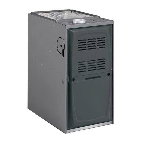
Upflow / Horizontal Left and Right Air Discharge
This manual must be left with the homeowner for future reference.
This is a safety alert symbol and should never be ignored. When you see this symbol on labels or in manuals, be alert to
the potential for personal injury or death.
A thermostat is not included and must be ordered
separately.
•
A Comfort Sync
thermostat must be used in
®
communicating applications.
•
In non-communicating applications, a traditional
non-communication thermostat may be used.
In all cases, setup is critical to ensure proper system
operation.
Field wiring for both communicating and non-
communicating applications is illustrated in these
instructions.
WARNING
Improper installation, adjustment, alteration, service
or maintenance can cause property damage, personal
injury or loss of life. Installation and service must be
performed by a licensed professional installer (or
equivalent), service agency or the gas supplier.
CAUTION
As with any mechanical equipment, personal injury can
result from contact with sharp sheet metal edges. Be
careful when you handle this equipment.
508249-01
INSTALLATION INSTRUCTIONS
A80US2V
Warm Air Gas Furnace
NOTICE
Table of Contents
Unit Dimensions ..........................................................2
Parts Arrangement.......................................................3
Gas Furnace ................................................................4
Shipping and Packing List ...........................................4
Safety Information .......................................................4
General ........................................................................6
Combustion, Dilution & Ventilation Air .........................6
Setting Equipment .......................................................8
Filters .........................................................................11
Duct System ..............................................................12
Venting.......................................................................12
Gas Piping .................................................................22
Electrical ....................................................................24
Thermostat ................................................................27
Blower Performance ..................................................39
Start-Up .....................................................................44
Other Unit Adjustments..............................................48
Heating Sequence of Operation ................................48
Service.......................................................................50
Planned Service ........................................................53
Repair Parts List ........................................................53
Integrated Control Diagnostic Modes ........................54
Integrated Control Diagnostic Codes.........................55
Allied Air Enterprises LLC
A Lennox International, Inc. Company
West Columbia, SC 29170
*P508249-01*
Issue 2205
Manufactured By
215 Metropolitan Drive
(P) 508249-01
Page 1 of 66
Advertisement
Table of Contents

Related Manuals for Allied A80US2V


Summary of Contents for Allied A80US2V
-
Page 1: Table Of Contents
Installation and service must be performed by a licensed professional installer (or equivalent), service agency or the gas supplier. Manufactured By Allied Air Enterprises LLC A Lennox International, Inc. Company 215 Metropolitan Drive West Columbia, SC 29170... -
Page 2: Unit Dimensions
Unit Dimensions NOTE - 20C and 20D size units installed in upflow applications that 3-1/8 (79) require air volumes of 1800 cfm (850 L/s) or greater must have one of the following: Single side return air with transition to accommodate 20 x 25 x 1in. -
Page 3: Parts Arrangement
Parts Arrangement Heat Exchanger Combustion Air Inducer Combustion Air Inducer Pressure Switch Rollout Located Valve Inside Burner Box Cabinet Burner Box Control Box (Includes Integrated Control, and Transformer) Burner Access Panel Blower Access Blower Assembly Panel Figure 1. Expanded View 508249-01 Issue 2205 Page 3 of 66... -
Page 4: Gas Furnace
Gas Furnace CAUTION The A80US2V gas furnace is shipped ready for installation As with any mechanical equipment, personal injury can in the upflow or horizontal position (left or right). The result from contact with sharp sheet metal edges. Be furnace is shipped with the bottom panel in place. The careful when you handle this equipment. - Page 5 MANUFACTURER’S This furnace may be installed in alcoves, closets, attics, EQUIPMENT LIMITED WARRANTY. ALLIED basements, garages, and utility rooms in the upflow or horizontal position. DISCLAIMS ALL LIABILITY IN CONNECTION WITH INSTALLER’S FAILURE TO FOLLOW THE ABOVE This furnace design has not been certified for installation in INSTALLATION INSTRUCTIONS.
-
Page 6: General
THE POLICIES AND CODES OF ALL REGULATING A portion of this information has been reprinted ENTITIES. ALL SUCH POLICIES AND CODES MUST BE with permission from the National Fuel Gas Code ADHERED TO. (ANSI-Z223.1). This reprinted material is not the complete and official position of the ANSI on the referenced subject, which is represented only by the standard in its entirety. - Page 7 Unconfined Space Air from Inside An unconfined space is an area such as a basement If the confined space that houses the furnace adjoins a or large equipment room with a volume greater than 50 space categorized as unconfined, air can be brought in cubic feet (1.42 m3) per 1,000 Btu (.29 kW) per hour of by providing two permanent openings between the two the combined input rating of all appliances installed in that...
-
Page 8: Setting Equipment
NOTE: Each air duct opening shall have a free area of at least one NOTE: The inlet and outlet air openings shall each have a free area square inch per 2,000 Btu (645 mm² per .59 kW) per hour of the total of at least one square inch per 4,000 Btu (645 mm²... - Page 9 Markings are provided on both sides of the furnace cabinet for installations that require side return air. Cut the furnace Units with 1/2 HP cabinet at the maximum dimensions shown on Page 2. Blower Motor NOTE: 20C and 20D units that require air volumes over 1800 cfm (850 L/s) must have one of the following: •...
- Page 10 (Upflow Applications Only - For Use with A, B, C and D Cabinets) Horizontal Applications The furnace can be installed in horizontal applications. Order horizontal suspension kit (51W10) from Allied Air, or use equivalent suspension method. Allow for clearances to combustible materials as indicated on the unit nameplate.
-
Page 11: Filters
Vent Connector Type C Type B1 Type *Front 2-1/4 in. (57 mm) 2-1/4 in. (57 mm) Back Sides 2 in. (51 mm) 2 in. (51 mm) Vent 6 in. (152 mm) 1 in. (25 mm) Figure 14. Horizontal Application Unit Installed on Platform Floor 0‡... -
Page 12: Duct System
Filter Size Venting Furnace Cabinet Width Side Return Bottom Return 14-1/2” 16 x 25 x 1 (1) 14 x 25 x 1 (1) A 4 inch diameter flue transition is factory installed on the combustion air inducer outlet of all models. Figure 16 17-1/2”... - Page 13 If necessary, reposition the combustion air inducer, pressure switch and/or make-up box per the following steps. See Figure 16 through Figure 22. Remove the four mounting screws (Figure 15) which secure the combustion air inducer / pressure switch assembly to the orifice plate. Lift the assembly and rotate it 90°...
- Page 14 • Disconnect pressure switch hose from barbed fitting on the Figure 22. Horizontal Right Position pressure switch assembly. Remove pressure switch assembly Side Vent Discharge (1 screw) and cut wire tie to free pressure switch wires. Reinstall pressure switch on the other side of orifice plate and reconnect pressure switch hose.
- Page 15 WARNING Asphyxiation hazard. The exhaust vent for this furnace must be securely connected to the furnace flue transition at all times. NOTE 1: Refer to the provided venting tables for installations. Refer to the capacity requirements shown in the provided venting tables. Figure 24.
- Page 16 NOTE: Refer to provided venting tables for installations. NOTE: The chimney must be properly sized per provided venting tables or lined with listed metal lining system. Figure 25. Common Venting Using Tile Lined Interior Masonry Chimney and Combined Vent Connector When inspection reveals that an existing chimney is not appliance categorized vent area, drafthood outlet safe for the intended purpose, it shall be rebuilt to conform...
- Page 17 Removal of the Furnace from Common Vent capacity). The horizontal length of the offset shall not exceed 1-1/2 feet (.46 m) for each inch (25 mm) of In the event that an existing furnace is removed from common vent diameter. a venting system commonly run with separate gas appliances, the venting system is likely to be too large to 10.
- Page 18 Capacity of Type B Double Wall Vents with Type B Double Wall Connectors Serving a Single Category I Appliance Vent and Connector Diameter - D (inches) 3 inch 4 inch 5 inch 6 inch Height H Lateral L (feet) (feet) Appliance Input Rating in Thousands of Btu per Hour NOTE: Single appliance venting configurations with zero lateral lengths are assumed to have no elbows in the vent system.
- Page 19 Capacity of Type B Double Wall Vents with Single Wall Metal Connectors Serving a Single Category I Appliance Vent and Connector Diameter - D (inches) 3 inch 4 inch 5 inch 6 inch Height H Lateral L (feet) (feet) Appliance Input Rating in Thousands of Btu per Hour NOTE: Single appliance venting configurations with zero lateral lengths are assumed to have no elbows in the vent system.
- Page 20 Vent Connector Capacity Type B Double Wall Vents with Type B Double Wall Connectors Serving Two or More Category I Appliances Vent and Connector Diameter - D (inches) Vent Connector 3 inch 4 inch 5 inch 6 inch Height H Rise R Appliance Input Rating in Thousands of Btu per Hour (feet)
- Page 21 Vent Connector Capacity Type B Double Wall Vents with Single Wall Metal Connectors Serving Two or More Category I Appliances Vent and Connector Diameter - D (inches) Vent 3 inch 4 inch 5 inch 6 inch Lateral L Height H (feet) Appliance Input Rating in Thousands of Btu per Hour (feet)
-
Page 22: Gas Piping
Leak Check Resize the common venting system to the minimum vent pipe size determined by using the appropriate tables in After gas piping is completed, carefully check all field- Appendix G of the current standards of the National Fuel installed piping connections for gas leaks. Use a Gas Code ANSI 2223.1. - Page 23 Gas Pipe Capacity - ft³/hr (m³/hr) Nominal Length of Pipe - feet (m) Internal Iron Pipe Diameter Size inches inches (mm) (mm) (3.048) (6.096) (9.144) (12.192) (15.240) (18.288) (21.336) (24.384) (27.432) (30.480) .622 (12.7) (17.799) (4.96) (3.40) (2.75) (2.32) (2.07) (1.87) (1.73) (1.61)
-
Page 24: Electrical
MANUAL MAIN SHUT-OFF Horizontal Application Horizontal Application VALVE Left-Side Air Discharge Right-Side Air Discharge MANUAL MAIN SHUT-OFF VALVE GROUND JOINT UNION GROUND DRIP LEG JOINT UNION DRIP LEG MANUAL MAIN SHUT-OFF VALVE GROUND JOINT FIELD UNION PROVIDED AND INSTALLED DRIP LEG NOTE: BLACK IRON PIPE ONLY TO BE ROUTED INSIDE OF CABINET Figure 28. - Page 25 Refer to Figure 40 for schematic wiring diagram and control configuration. This terminal is energized in the troubleshooting and Figure 41 for field wiring. heating mode whenever the combustion air inducer is operating. The power supply wiring must meet Class I restrictions. Install the room thermostat according to the instructions Protected by either a fuse or circuit breaker, select circuit protection and wire size according to unit...
- Page 26 Switch 2 — Second Stage Delay (Used with Single- Connect a sufficiently sized wire with ground to the furnace’s line voltage connections and ground wire. Refer Stage Thermostat Only) to the furnace rating plate for electrical characteristics This switch is used to determine the second stage on to be used in sizing field supply wiring and overcurrent delay when a single-stage thermostat is being used.
-
Page 27: Thermostat
Thermostat DATS (Optional) OATS (Optional) Communicating Communicating Outdoor Unit Indoor Unit Smart Hub Display Subbase Figure 31. Comfort Sync A3 with Communicating Indoor and Outdoor Units DATS (Optional) OATS (Optional) SETUP NOTES: CUT Y1-Y2 ON-BOARD MUNICATING) CUT R-O ON-BOARD LINK FOR OUTDOOR HEAT MUNICATING) Smart Hub... - Page 28 DATS (Optional) OATS (Optional) SETUP NOTE: CUT Y1-Y2 ON-BOARD LINK FOR 2-STAGE OUTDOOR UNITS (NON-COMMUNICATING) Smart Hub Display Subbase 24VAC Outdoor Unit Communicating (1 - or 2-Stage Indoor Unit Air Conditioner) Figure 33. Comfort Sync A3, Communicating Indoor Unit with 24VAC Air Conditioner Communicating Outdoor Unit If jumber is present between...
- Page 29 Indoor Unit Controller Outdoor Unit Smart Hub HD Display Subbase 12VDC COM BUS ACC1 ACC2 R i+ I- C +12V -12V Single wire Single wire to indoor unit to bundle terminal “C”. wire to indoor Single wire terminal “C”. to terminal “C”. Unused wires Unused wires Unused wires...
- Page 30 24VAC “H” and 120VAC “H” outputs to cycle humdifier based on demand. No other control or humidistat is required. Optional outdoor air temperature sensor for use with humidifier (if not already in the system for other function and are typically built into all Allied communicating outdoor units...
- Page 31 Communicating Indoor Unit HRV/ERV Terminal Block Smart Hub Display Subbase Wire Jumper required between ON and RED terminals. ACC1 is always low-stage for single- and two-stage ventilators. Figure 39. Comfort Sync A3 with Ventilation (Fresh Air Damper, ERV and HRV) 508249-01 Issue 2205 Page 31 of 66...
- Page 32 DIP Switch Settings and On-Board Links Thermostat Wiring Connections DIP Switch 1 On Board Links Must Be Cut To Select System Options FURNACE OUTDOOR T'STAT TERM. STRIP UNIT 1 Heat / 1 Cool NOTE: Use DIP DO NOT CUT ANY switch 2 to set ON-BOARD LINKS sceond-stage heat...
- Page 33 DIP Switch Settings and On-Board Links Thermostat Wiring Connections DIP Switch 1 On Board Links Must Be Cut To Select System Options FURNACE OUTDOOR T'STAT TERM. STRIP UNIT 2 Heat / 2 Cool CUT ON-BOARD LINK W915 2 STAGE COMPR *Not required on all units FURNACE OUTDOOR...
- Page 34 DIP Switch Settings and On-Board Links Thermostat Wiring Connections DIP Switch 1 On Board Links Must Be Cut To Select System Options FURNACE HEAT PUMP TERM. STRIP T'STAT CUT ON-BOARD LINK 67M41* W951 Dual Fuel Single- HEAT Stage Heat Pump PUMP Thermostat w/dual fuel capabilities...
- Page 35 DIP Switch Settings and On-Board Links Thermostat Wiring Connections DIP Switch 1 On Board Links Must Be Cut To Select System Options FURNACE HEAT PUMP TERM. STRIP T'STAT Dual Fuel Single- 67M41* Stage Heat Pump CUT ON-BOARD LINK Thermostat w/dual W951 fuel capabilities HEAT...
- Page 36 Figure 40. A80US2V Schematic Wiring Schematic Page 36 of 66 Issue 2205 508249-01...
- Page 37 Figure 41. Typical A80US2V Field Wiring Diagram 508249-01 Issue 2205 Page 37 of 66...
- Page 38 RS-BUS TERMINAL BLOCK THERMOSTAT CONNECTIONS (TB1) I+ = DATA HIGH CONNECTION DS = DEHUMIDIFICATION SIGNAL I- = DATA LOW CONNECTION W2 = HEAT DEMAND FROM 2ND STAGE TSTAT W1 = HEAT DEMAND FROM 1ST STAGE TSTAT RS-BUS TERMINAL BLOCK R = CLASS 2 VOLTAGE TO TSTAT R = 24VAC G = MANUAL FAN FROM TSTAT I+ = DATA HIGH CONNECTION...
-
Page 39: Blower Performance
Blower Performance A80US2V070A12(L) BLOWER PERFORMANCE (less filter) 0 through 0.8 in. w.c. (Heating) and 0 through 1.0 in. w.c. (Cooling) External Static Pressure Range HEATING Heating Speed Dip Switch Setting First Stage Heating Speed - cfm Second Stage Heating Speed-cfm +24% 1073 1178... - Page 40 A80US2V090B16(L) BLOWER PERFORMANCE (less filter) 0 through 0.8 in. w.c. (Heating) and 0 through 1.0 in. w.c. (Cooling) External Static Pressure Range HEATING Heating Speed Dip Switch Setting First Stage Heating Speed - cfm Second Stage Heating Speed-cfm +24% 1353 1488 +18% 1287...
- Page 41 A80US2V110C20(L) BLOWER PERFORMANCE (less filter) 0 through 0.8 in. w.c. (Heating) and 0 through 1.0 in. w.c. (Cooling) External Static Pressure Range HEATING Heating Speed Dip Switch Setting First Stage Heating Speed - cfm Second Stage Heating Speed-cfm +24% 1693 1860 +18% 1611...
- Page 42 Allowable Heating Speeds Model -18% -12% Default +12% +18% +24% A80US2V070A12 Allowed Allowed Allowed Factory Setting Allowed Allowed Allowed Allowed A80US2V090B12 Allowed Allowed Allowed Factory Setting Allowed Allowed Not Allowed Not Allowed A80US2V090B16 Allowed Allowed Allowed Factory Setting Allowed Allowed Allowed Allowed A80US2V090C20...
- Page 43 PMW signal from the control will be lines “=” are displayed blocked and also lead to control damage. Refer to Table 23 for operation sequence in applications including A80US2V, • 10 minutes of entering the flame sense mode.
-
Page 44: Start-Up
Start-Up WARNING For Your Safety, Read Before Operating If you do not follow these instructions exactly, a fire or explosion may result causing property damage, personal injury, or loss of life. WARNING Do not use this furnace if any part has been under Gas Valve Operation water. - Page 45 Turning Off Gas to Unit Gas Meter Clocking Chart Set the thermostat to the lowest setting. Seconds for One Revolution Turn off all electrical power to the unit if service is to SL280 Natural be performed. Unit 1 cu ft 2 cu ft 1 cu ft 2 cu ft...
- Page 46 73W35 No Change 69W56 73W35 No Change 73W33 73W34 Table 22. High Altitude Pressure Switch Kits A80US2V, Non-Communicating Thermostat with Humidity Control Feature and Single-Speed Outdoor Unit Operating Sequence System Demand System Response Thermostat Demand Relative Humidity Blower System Step...
- Page 47 A80US2V, Non-Communicating Thermostat with Humidity Control Feature and Two-Speed Outdoor Unit Operating Sequence System Demand System Response Thermostat Demand Relative Humidity Blower System Step Compressor Comments Condition (COOL) Status NO CALL FOR DEHUMIDIFICATION Normal Operation Acceptable 70%* Compressor and indoor...
-
Page 48: Other Unit Adjustments
stabilized, check the temperature rise. If necessary, adjust Other Unit Adjustments the heating blower speed to maintain the temperature rise within the range shown on the unit nameplate. See Table 14 for allowable heating speeds. Increase the blower Primary and Secondary Limits speed to decrease the temperature rise. - Page 49 NOTE: The ignition control thermostat selection DIP switch If second stage heat is required, the thermostat is factory set in the “TWO STAGE” position. second stage heat contacts close and send a signal to the integrated control. The integrated control initiates a 30-second second stage recognition delay.
-
Page 50: Service
Filters combustion air inducer at high speed. The control also All A80US2V filters are installed external to the unit. Filters checks the high fire (second stage) pressure switch to should be inspected monthly. Clean or replace the filters make sure it is closed. - Page 51 See Figure 48. Remove screws securing burner box and remove burner box. Figure 47. A80US2V Burner, Combustion Air Inducer Assembly & Heat Exchanger Removal 508249-01 Issue 2205 Page 51 of 66...
- Page 52 15. NOX units only - replace NOX insert. 16. Reinstall collector box and combustion air assembly. Reinstall all screws to the collector box and combustion air inducer. Failure to replace all screws may cause leaks. Inspect gaskets for any damage and replace if necessary.
-
Page 53: Planned Service
Planned Service The following items should be checked during an annual inspection. Power to the unit must be shut OFF for the service technician’s safety. Fresh air grilles and louvers (on the unit and in the Operating performance - Unit must be observed during room where the furnace is installed) - Must be open and operation to monitor proper performance of the unit and unobstructed to provide combustion air. -
Page 54: Integrated Control Diagnostic Modes
Integrated Control Diagnostic Modes Display Action (when button released) No change (idle)* Remain in idle mode Solid “E” Enter diagnostic recall mode Solid “U” Discharge air installed Solid “F” Enter flame signal mode Solid “P” (variable speed only) Program unit capacity/size (Unit Code)** * No change implies the display will continue to show whatever is currently being displayed for normal operation (blinking decimal, active error code, heat state, etc.) ** After the “P”... -
Page 55: Integrated Control Diagnostic Codes
Integrated Control Diagnostic Codes Code Diagnostic Codes / Status of Equipment Action Required to Clear and Recover E000 No errors in memory. E105 Device communication problem - No other devices Equipment is unable to communicate. Indicates on RS BUS (Communication system). numerous message errors. - Page 56 Integrated Control Diagnostic Codes (continued) Code Diagnostic Codes / Status of Equipment Action Required to Clear and Recover E131 Corrupted control parameters (Verify configuration Reconfigure the system. Replace control if heating of system) (Communicating systems only). or cooling is not available. Only applicable in the communicating mode not in startup.
- Page 57 Integrated Control Diagnostic Codes (continued) Code Diagnostic Codes / Status of Equipment Action Required to Clear and Recover E224 Low pressure switch failed closed -Refer to Check pressure(inches W.C) of low pressure switch troubleshooting closing on heat call. Measure operating pressure (inches w.c.).
- Page 58 Integrated Control Diagnostic Codes (continued) Code Diagnostic Codes / Status of Equipment Action Required to Clear and Recover E273 Soft lockout - Exceeded maximum number of Check micro-amperes of flame sensor using control recycles. Last recycle due to flame failure diagnostics or field installed mode.
- Page 59 Integrated Control Diagnostic Codes (continued) Code Diagnostic Codes / Status of Equipment Action Required to Clear and Recover E313 Indoor or outdoor unit capacity mismatch. Incorrect indoor/outdoor capacity code selected. Check Communication only. for proper configuring in installation instructions. Alarm is just a warning.
- Page 60 Program Unit Capacity / Size Mode Power-Up - Number displayed by integrated control represents unit size code (furnace model and capacity). If three horizontal bars are displayed followed by continuous E203, furnace control does not recognize unit size code. Configure per the following: Turn room thermostat to OFF.
- Page 61 Troubleshooting: Heating Sequence of Operation 508249-01 Issue 2205 Page 61 of 66...
- Page 62 Troubleshooting: Heat Sequence of Operation (continued) Page 62 of 66 Issue 2205 508249-01...
- Page 63 Troubleshooting: Heat Sequence of Operation (continued) 508249-01 Issue 2205 Page 63 of 66...
- Page 64 Troubleshooting: Heat Sequence of Operation (continued) Page 64 of 66 Issue 2205 508249-01...
- Page 65 Troubleshooting: Continuous Fan Sequence of Operation 508249-01 Issue 2205 Page 65 of 66...
- Page 66 Requirements for Commonwealth of Massachusetts Modifications to NFPA-54, Chapter 10 INSPECTION. The state or local gas inspector of the side wall, horizontally vented, gas-fueled equipment Revise NFPA-54 section 10.8.3 to add the following shall not approve the installation unless, upon requirements: inspection, the inspector observes carbon monoxide For all side wall, horizontally vented, gas-fueled equipment...
Need help?
Do you have a question about the A80US2V and is the answer not in the manual?
Questions and answers